You are using an out of date browser. It may not display this or other websites correctly.
You should upgrade or use an alternative browser.
You should upgrade or use an alternative browser.
ENGINE SPEED GOVERNORS
- Thread starter Brian Rupnow
- Start date

Help Support Home Model Engine Machinist Forum:
This site may earn a commission from merchant affiliate
links, including eBay, Amazon, and others.
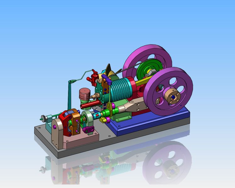
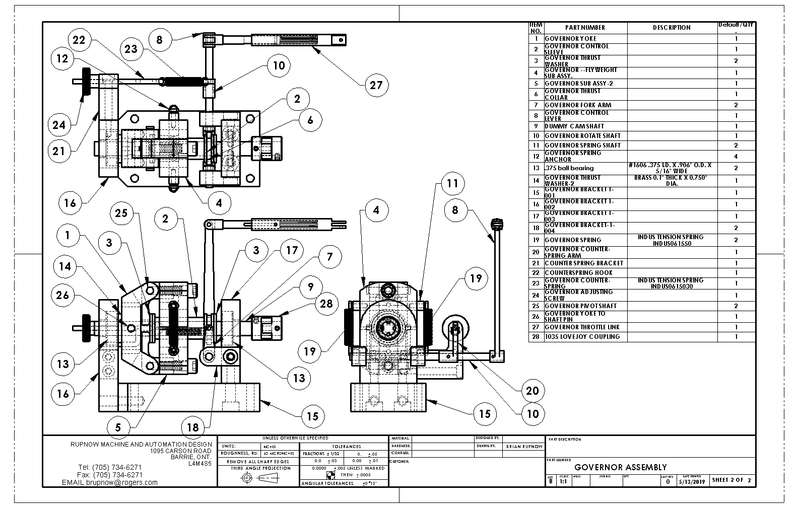
The link that ties the governor arm to the carburetor throttle arm isn't going to be rocket science. Just a turned brass end and a piece of 1/16" diameter bent wire. My Lovejoy coupling won't be here until Thursday, so maybe tomorrow I will make the machined brass part of the link. I won't bend the wire until the governor is bolted down in it's final position, as dictated by the coupling.


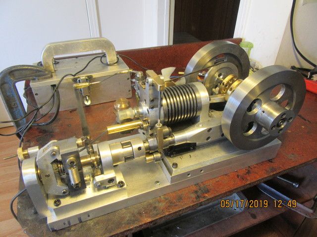
We are ready to Rock and Roll!!! My Lovejoy coupling came in this morning and I immediately went down to Canadian Bearings and picked it up. Some of you may wonder why I waited until I had the coupling before I drilled the holes in the sub base to mount the governor to it.--Well, it's a matter of trust. I simply don't trust the solid models that are available from suppliers websites.---and in this case, my distrust was quite justified. The solid model I downloaded from Lovejoy had the center spider at 0.280" thick. In reality, it measures at about 0.400" thick. If I had positioned the governor based on their 3D cad model, all of my drilled and tapped holes would have been out by half a hole. Two years ago, a company I was doing some work for had me design about 15 dies based on the customer supplied 3D cad models. The dies were designed, machined, and sent to the customer. The parts they made from the dies were all way out of spec. What the Hell??? Turns out the customer parts had went thru 3 or 4 revisions and nobody updated the solid models. They fired the guy responsible at their end and the guy I was doing the work for had to eat about $30,000 in rework of all the dies. I have finished the link between the governor and the carburetor to what I hope is the correct length and soldered the ends on. I'm going to go eat a bowl of soup and give the Loctite holding the pivot pins for the linkage time to set up a bit, and then start things up and see what happens.


It works!! I had to take one of the springs off the governor body, because it just wasn't sensitive enough with two springs on. Now I can start the engine and let the governor adjust the rpm the engine runs at in a no load situation. When I push hard on one flywheel with my thumb to load up the engine, you can see and feel the governor reacting to the load by opening the throttle to give the engine more gas to keep the rpm that the governor wants. I will now try and make a video of this so you can see the action happening.
This is the video which shows the governor working to maintain a constant rpm at the engine, whether it is in a "no load" situation or a "loaded" situation. I am pleased, it does work quite well. I may, in future, hook the engine up to some machine I build, but for now my thumb works pretty good as a "loading device".---Brian
nel2lar
Well-Known Member
Brian
Congratulation is in order on this one. You earned your title of engine designer. She is a beauty and runs very nicely, the governor is doing everything it is made to do. Now take a well deserved break.
Again, you did it.
Nelson
Congratulation is in order on this one. You earned your title of engine designer. She is a beauty and runs very nicely, the governor is doing everything it is made to do. Now take a well deserved break.
Again, you did it.
Nelson

$12.56
$39.95
Complete Plans for Building Horse Barns Big and Small(3rd Edition)
ThriftBooks-Atlanta
![DreamPlan Home Design and Landscaping Software Free for Windows [PC Download]](https://m.media-amazon.com/images/I/51kvZH2dVLL._SL500_.jpg)
$0.00
DreamPlan Home Design and Landscaping Software Free for Windows [PC Download]
Amazon.com Services LLC

$39.99
$49.99
Sunnytech Low Temperature Stirling Engine Motor Steam Heat Education Model Toy Kit For mechanical skills (LT001)
stirlingtechonline

$45.99
Sunnytech Mini Hot Air Stirling Engine Motor Model Educational Toy Kits Electricity HA001
stirlingtechonline

$29.95
Competition Engine Building: Advanced Engine Design and Assembly Techniques (Pro Series)
Amazon.com Services LLC

$99.99
AHS Outdoor Wood Boiler Yearly Maintenance Kit with Water Treatment - ProTech 300 & Test Kit
Alternative Heating & Supplies

$519.19
$699.00
FoxAlien Masuter Pro CNC Router Machine, Upgraded 3-Axis Engraving All-Metal Milling Machine for Wood Acrylic MDF Nylon Carving Cutting
FoxAlien Official

$24.99
$34.99
Bowl Sander Tool Kit w/Dual Bearing Head & Hardwood Handle | 42PC Wood Sander Set | 2" Hook & Loop Sanding Disc Sandpaper Assortment | 1/4" Mandrel Bowl Sander for Woodturning | Wood Lathe Tools
Peachtree Woodworking Supply Inc

$94.99
$109.99
AHS Woodmaster 4400 Maintenance Kit for Outdoor Wood Boiler Treatment
Alternative Heating & Supplies

$40.02
$49.99
Becker CAD 12 3D - professional CAD software for 2D + 3D design and modelling - for 3 PCs - 100% compatible with AutoCAD
momox Shop

$89.99
Outdoor Wood Boiler Water Treatment Rust Inhibitor- AmTech 300 & Test Kit
Alternative Heating & Supplies
stragenmitsuko
Well-Known Member
- Joined
- Jan 19, 2016
- Messages
- 327
- Reaction score
- 143
A good load for this would be an ac generator .
The rpm determines the frequency , wich is usually 50 or 60Hz .
Then the alternator could be loaded with an ac motor or some light bulbs and the governor would
have to work to maintain rpm .
Great work brian
The rpm determines the frequency , wich is usually 50 or 60Hz .
Then the alternator could be loaded with an ac motor or some light bulbs and the governor would
have to work to maintain rpm .
Great work brian
- Joined
- Oct 1, 2010
- Messages
- 1,408
- Reaction score
- 435
Wonderful,
I enjoyed the entire design and build of the engine, and then the governor.
Congratulations on a very successful build and thank you again for all your postings.
--ShopShoe
(Tongue in Cheek)
What stragenmitsuko said above: I think a generator and a variable load on it would work great with what has been built so far, but I understand you really love mechanical devices and not electrical systems. What about a fluid (water?) system that would require a pump, a reservoir, and maybe a needle valve or two? (Made out of clear plastic so you can see the fluid?)
--SS
This is the video which shows the governor working to maintain a constant rpm at the engine, whether it is in a "no load" situation or a "loaded" situation. I am pleased, it does work quite well. I may, in future, hook the engine up to some machine I build, but for now my thumb works pretty good as a "loading device".---Brian
Great Job thanks for sharing!
Rick
Thank you all, gentlemen. That all went very well, with no re-do's or scrapped parts. I do have a really nifty over-center clutch to power from the engine output, but at the moment I don't have much machinery to put on the other side of the clutch. I really appreciate it when people comment on my builds. ---Brian
And for Luc---You were right. The governor only needed the one spring to work correctly. I built this governor almost exactly to the original drawings by Edgar Westbury, as shown on the first page of this thread, and he showed two springs, so that's what I did. I have always followed the principle that if I`m not really sure, go by the drawing. If I have to tweak things a bit after something is built, I will.---Brian
JohnBDownunder
Well-Known Member
- Joined
- Mar 1, 2012
- Messages
- 112
- Reaction score
- 36
Thanks once again for an enjoyable, educational thread Brian. Any of your threads are a magnet for me.
John B
John B
I looked around my shop for flat belts, but I only found this short little guy to run my over-center clutch.
canadianhorsepower
Well-Known Member
- Joined
- Oct 22, 2011
- Messages
- 1,671
- Reaction score
- 324
Thanks Brian, very nice work, as usual. Now if you want to try something that will get your governor workingAnd for Luc---You were right. The governor only needed the one spring to work correctly. I built this governor almost exactly to the original drawings by Edgar Westbury, as shown on the first page of this thread, and he showed two springs, so that's what I did. I have always followed the principle that if I`m not really sure, go by the drawing. If I have to tweak things a bit after something is built, I will.---Brian
so fast, you want notice the change in RPM ,but only the arm reaction. Remove the second spring on your counter weight. All you will ear
is engine noise( working harder) and no RPM change. anyway THUMB UP
Similar threads
- Replies
- 123
- Views
- 16K


