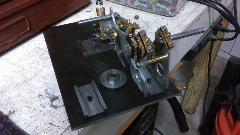
ET Westbury Side Paddle Engine

Home Model Engine Machinist Forum

Help Support Home Model Engine Machinist Forum:

This site may earn a commission from merchant affiliate links, including eBay, Amazon, and others.
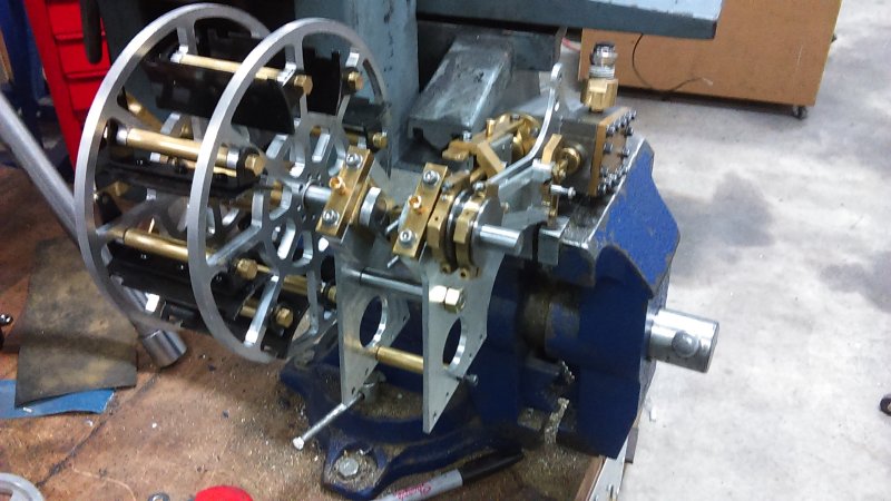
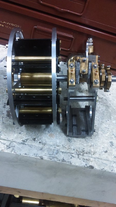
A small step backwards last night. I had decided to do a remake on the stay bars that hold all 4 frames together, and to install it I needed to remove the paddle wheels. They were stuck! Apparently the setscrew had raised a burr on the crankshaft arm. In attempting to wrestle one off the starboard engine I twisted the web loose. And since the shaft itself it now scored, I need to remake the crankshaft, hence a partial disassembly.

This time I'll mill a small flat on the crankshaft so that a burr there won't prevent the paddlewheel from coming off. I think that for transport to shows removing the paddles will be a good idea anyway.
 
I am also in the process of making one of these models.
But to be honest I have so many projects on the go, including a 5" Shay loco, that I cheated a bit, and got the paddles laser cut for me from Stainless steel by model engineers laser www.modelengineerslaser.co.uk in the UK.
found they look good and also much thinner so more to scale, and once fitted look perfect.
Hope to get the engine completed very soon.
Chris

DSCN0312.jpg


DSCN0314.jpg


View attachment Edgar Westbury Paddle Wheel.pdf
 
Your pretty engine makes mine hang its head in shame. :mad:

I see you didn't cut the notches in the floats. Are they hitting the frame?

Looking forward to seeing a video. D

BTW, you have the paddle wheel on the wrong side (I know this was just a test fit). :)
 
After various delays due to the season plus a bit of laziness, it's taken me a while to remake the starboard crankshaft. Originally I was just going to replace the outboard shaft, but then decided starting over was a better option. This time I pinned the webs on both ends using 1/16" drill rod pins held with loctite and then filed flush.

Also made a second adapter to allow connecting 1/4" air tube to the 1/16 NPT inlet in case I ever get the two engined working together.

Reassembled, and now need to retime:

large.jpg


I've also decided that rather than angle brackets to attach the feet of the frames to the base individually, I'll make a single bracket for each pair. I think that will guarantee the frames stay parallel more easily.
 
The engine looks really great. Havent done much on mine due to the heat wave down here.
 
After a quick try at timing I tested the engine with the new crank. Ran well in forward, nada in reverse. I'll take another try tomorrow. Today I made a bracket to fasten the two frames together at the base. Started with some 3/8" thick HRS bar. Seems to work well, so I'll make another for the port engine and a third to attach the two inner frames on the other end. Thses three brackets will be attached to a base plate with screws.

large.jpg
 
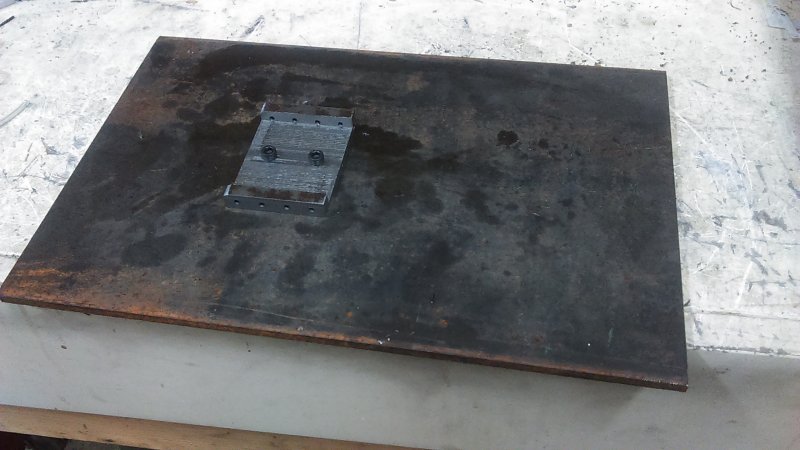
A friend donated a piece of 8"x1/4" HRS that will eventually serve as a base for the engine. I took another piece of 3/8" HRS and carved out the bracket to connect the inner frames at the cylinder end. It's 2.75" wide, hence the same as the stay bars. It's attached to the base by a couple of 10-32 screws.

large.jpg


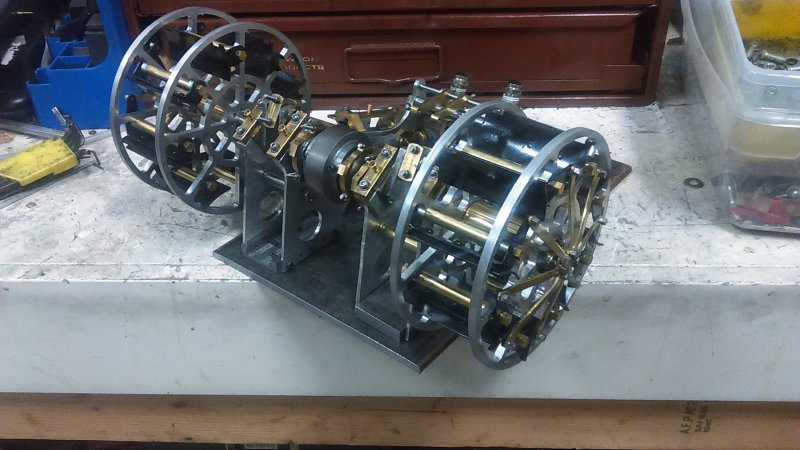
Did a test fit of the engines to this bracket. Other than being awkward to get the screws started, it worked well enough to get both engines attached and lined up. Since the front brackets between the inner and outer frames aren't done and attached, it's unclear how much shimming might be needed to get the crankshafts aligned well enough to avoid any binding. As they are with the coupling attached, both engines do turn fairly freely together.

large.jpg


Weighed it as shown above - 18 pounds / 8 kg
 
Got the 3rd bracket attached to the base with the port engine attached to verify fit.

large.jpg


Also split the temporary coupler I'd been testing with. The two halves will be joined by screws, allowing decoupling when needed.
 
So having applied air to the port engine in the configuration shown above, I found a leaky steam chest since I'd not tightened the screws on the cover since the last reassembly. After snugging up there's still some leakage at the corners since I have an issue with threading the corner screws all the way through the cover/chest/frame to the cylinders. I think I need to enlarge the 4 corner holes in the chest a few thou.

In any case, even with the leaks the engine still runs in reverse with enough pressure applied and a manual assist on turning the paddles. The main problem is that it then runs at high RPMs, and when pressure is reduced to a reasonable speed slows down until it stops. Still doesn't run forward. Also, the high speed running causes enough flex even with the frame mounts to loosen quite a few screws. So I'm not sure how much work/rework is needed on both sides to get a slow enough motion to run reliably for a long period, which is a necessity to exhibit at Cabin Fever 3 weeks from now. With both engines mounted there will be the two stay bars between the inner frames, and those may quell some of the vibrations.

Feeling a bit frustrated, i decided to spend Xmas afternoon cleaning swarf from my machinery, something that's been neglected for quite a while. Before that I needed to empty a year's worth from the shop vac. Filled a plastic sac that's almost too heaving to lift. Now I'm going to sweep the floors and try to put tools and stuff where they belong. Maybe having a clean workbench will make be more enthusiastic for engine work.
 
Today I decided to make 4 studs for the cylinder/chest assembly as an experiment. Because the fasteners go through the cover, chest, frame, and into the cylinder, plus through 3 gaskets, it's quite a feat of dexterity to get everything lined up. And when you need to remove the cover to see the valve during timing, it's another hassle.

With studs you can leave them in place and remove the cover, keeping the rest aligned.

I don't have enough material for replacing all the screws with studs, and with 12 holes to line up, screws are easier. So I'll stick with 4 per engine. The 4 I made were slightly too short, but did prove the concept. I'll remake them a bit longer next time in the shop.
 
Some better progress the past three days on the port engine. I decided from the past trials that I had way too much air leaking to get a good test. I needed high pressure to get it started, and then it wouldn't run at a low speed. So I took the bull by the horns and first remade the piston in bronze vs. the original brass, and with a much better fit (~.001" total clearance).

The second step was to make 5 gaskets from 1/32" thick paper gasket stock. This is much tougher and pliable than the .010" teflon sheet I'd used earlier. Following the same recipe as with the loco, I coated the gaskets with a combination of thick steam oil and graphite powder.

Third step was to make some packing of teflon thread for the piston and valve glands.

And finally figured out the easiest way for me to time the valve gear.

After all that I had one irritating problem with the crankshaft sticking at one spot in its rotation. An hour of turning on the lathe didn't loosen it up. After lots of trying various things I discovered the problem to be the inner eccentric being too close to the bearing. Moving the eccentrics outward a smidge freed things up. Applied air and it took off.

I still have to hold the weigh shaft in position as there's no reversing mechanism in place yet. After the first trials I substituted the 1/4" air tune with the 1/8" tube, and it still ran fine. Here's a short vid:


[ame]https://www.youtube.com/watch?v=GLaCysPrmuo&feature=youtu.be[/ame]
 
Its alive. Well done Kvom. Looks like ive got some adjustments ahead of me when the weather here cools down a bit.
 
This weekend I performed the same operations on the starboard engine as on its buddy (new piston, gaskets), did the valve tuning, and applied air. Discovered some dumbassery on my part in that I switched the forward/reverse timing, something that would not work well with the engines connected.

Next time in the shop I'll redo the timing and try again. The timing itself is getting quite easy; it's unfastening the 12 screws to open the steam chest cover that is tedious, as well as messing with the 2-56 screws and nuts that fasten the eccentric straps.

Have you considered using clear acrylic or Lexan to make a temp cover
so you can see in? Should work fine with air...

Pete
 
The clear cover would have been more useful when I was struggling with leaning to do the timing, but I wouldn't want it on a finished model. Hopefully this will be the last time I'll need to do it.
 
Thats a great runner. Thanks for sharing
 
I discovered that with the longer crankshafts needed for the paddles that the assembled engine will not fit in either of my standard toolboxes that I was planning to use to carry it on the plane to CF. Separating the engines and the base will make it harder to pack securely, but I'll see if it's possible.

I did come up with a scheme for a reverser, as shown in the attachment. A 3" long lifting rod will be attached to the ends of both weigh shaft arms, and its other end will be attached to a 5" long rod with a pivot point in the center. I will need a means to secure the end of the pivot in both forward and reverse positions. As shown in the diagram, the weigh shaft needs to pivot 30 degrees between the two, and the ends of the pivot rod will move ~ 3/4".

reverser.jpg
 
With NAMES on the horizon I decided I'd try to get the starboard engine working, with crankshaft #3 needed. Stan Shire turned me onto the use of Tix low-temp jewelry solder, and with the solder and flux having arrive last week I did an experiment as to whether this solder would be a good choice for a built-up crank vs. the loctite I've tried previously.

I drilled and reamed a .376" hole in some scrap steel 1/4" HRS and cut off a small piece of 3/8" drill rod for the experiment. I dipped the drill rod in the flux and inserted it halfway into the hole. Then heated the rod from below while applying the solder from above. I needed to push the solder pieces into contact with the rod, but once I did so it wicked all around and full depth.

The solder doesn't set hard until the temperature cools, but once I ran cold water over the piece the joint appears very solid. It would be interesting to see what sort of force this joint will sustain under an arbor press.

IMAG0223.jpg
 

Latest posts

Back
Top