arnoldb
Well-Known Member
- Joined
- Apr 8, 2009
- Messages
- 1,792
- Reaction score
- 12
Having fitted the DRO to my mill, I looked through my list for a project to try it out and get to grips with it. Even though I have an itch to build a complex and detailed engine, I thought something fairly simple would be better to try out the DRO to get the gist of working with it.
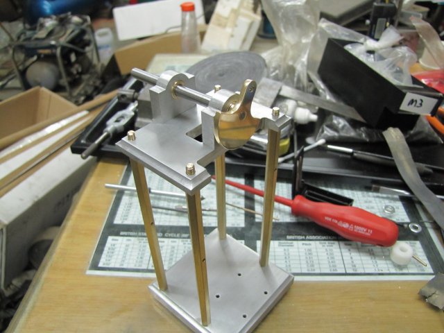
One of Elmer's would do. The collection of engines on my side-board are growing, but there's a lack of height there, so I settled on Elmer's #32 as a relatively simple engine (compared to the Kimble and Coombers) that has a fair amount of work that can be done on the mill, as well as adding some height to the collection.
I'm not going to go overboard on this build; for the most part I'm going to build it exactly to plans. One exception will be that I'm going to add a slip-eccentric to make it reversible, as this is very easy to add to this engine as a custom touch.
Don't expect too many photos, but if there are any members that would like more detail on certain bits or processes of the build, please ask (publicly, or pop me a personal message), and I'll be happy to accommodate. Any suggestions or criticism is also welcome")
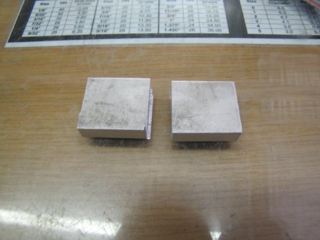
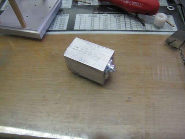
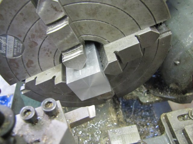
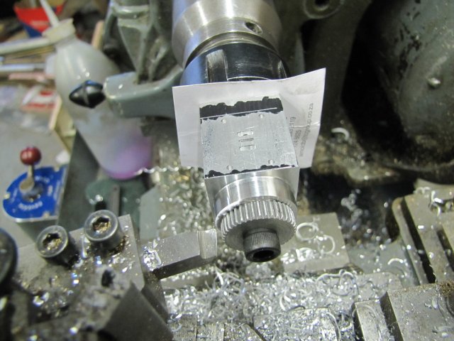
I started off with sawing a 78x78x12mm bit of aluminium from a sheet of 12mm plate I have. That was roughly squared up, and then I brought out a bit of kit I have that I've used rarely before - the venerable edge finder. Mine is of slightly dubious quality, and I've never really bothered to set up test equipment on the mill to check it's accuracy and repeatability. Another disadvantage that I had with the edge finder is that it is 5mm in diameter, and my mill's feed screws are 3mm per turn, meaning that in the past I had to be careful about finding an edge and setting the zero-able hand wheel dials correctly to obtain my datum point. So first things first, I tested the edge finder - and much to my surprise it ended up repeatable within 0.005mm (1/5 of a thou) in four out of five tests - that's much better than I expected, and plenty good enough for my shop; 0.01mm repeatability would be fine with me. With the DRO, backlash becomes a lot less important, and it's easy to set absolute zero.
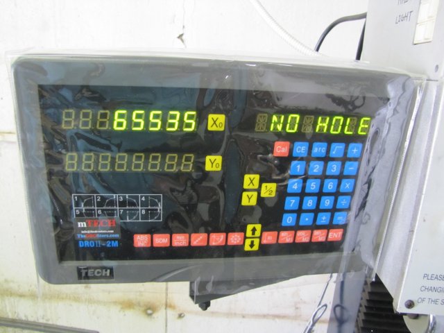
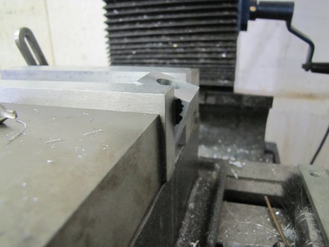
Next I put the DRO to test; I located the right-hand back edge of the workpiece; I tend to work from the right-hand side of the vise as that way I end up with the least amount of chips thrown toward myself while milling, and the fixed end of the vise jaw remains in position on the Y axis. The block of aluminium plate was then properly squared up to size, with the aid of the vise stop.
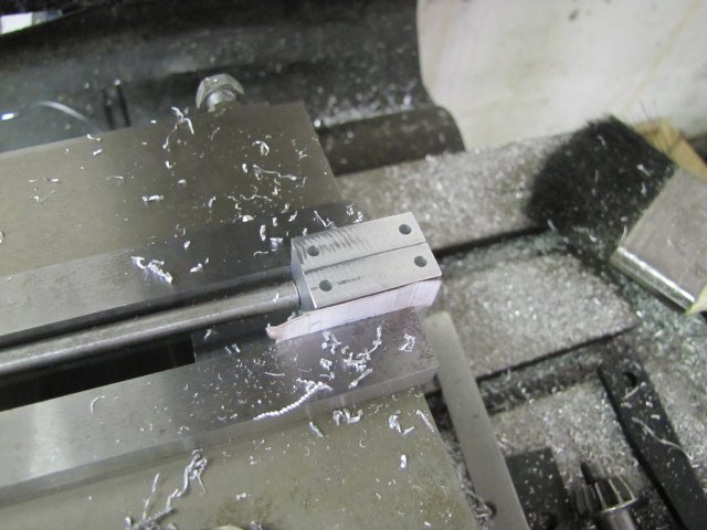
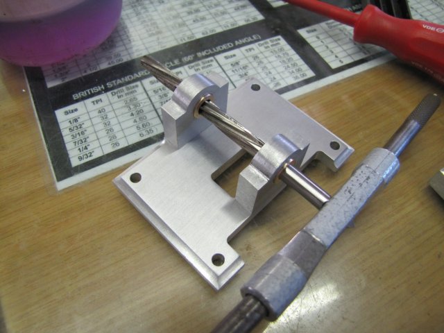
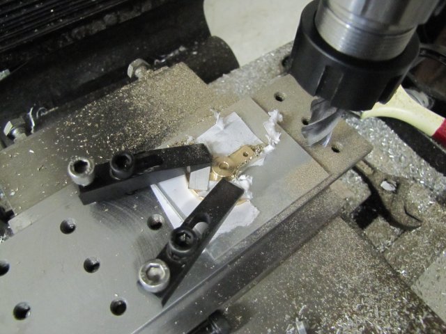
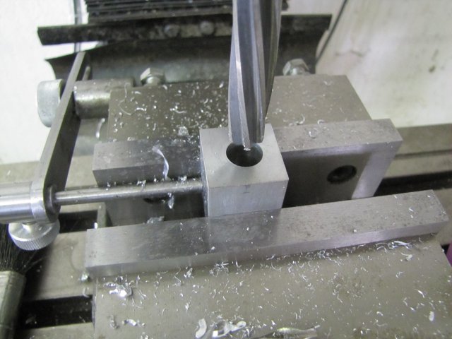
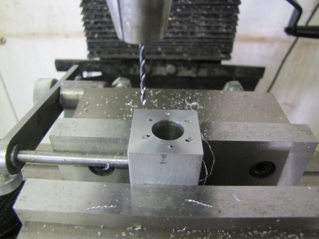
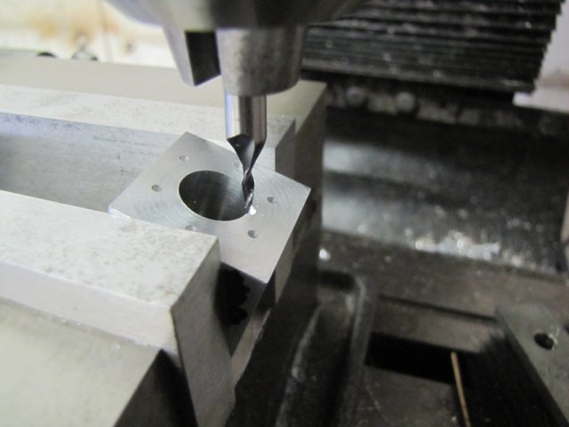
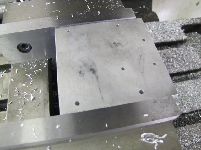
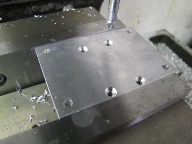
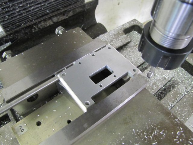
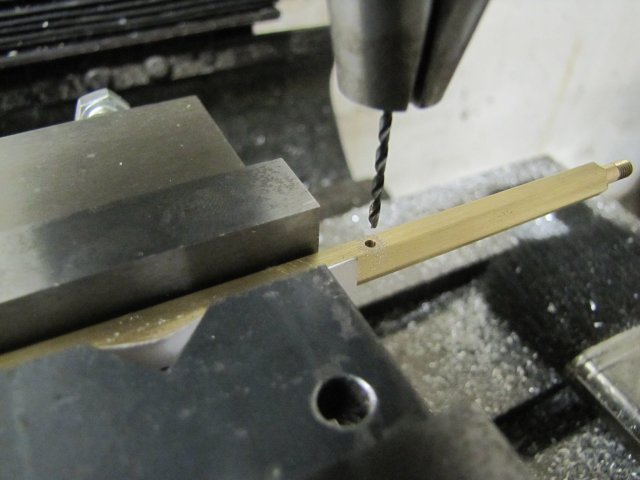
For the next step, I didn't lay out anything; I simply coordinate drilled four 3mm clearance holes and the small square's 2.5mm tapping holes for M3 using the DRO and incremental readings:
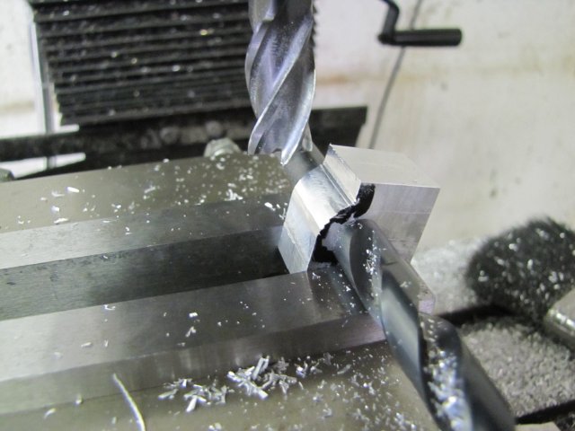
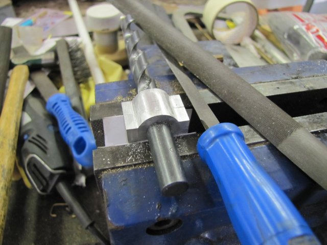
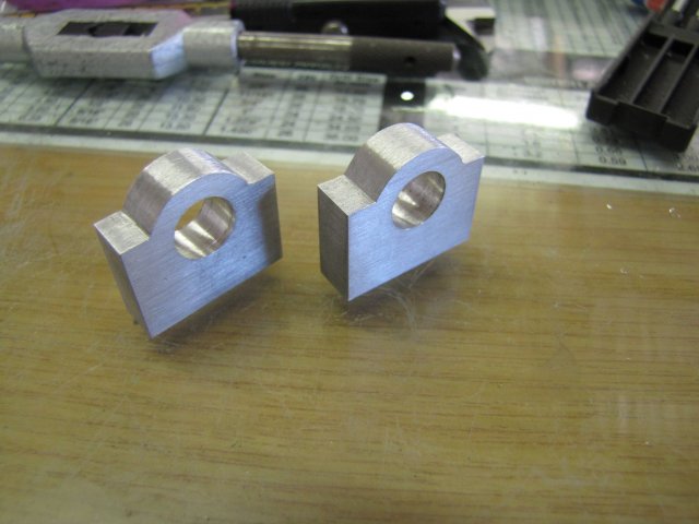
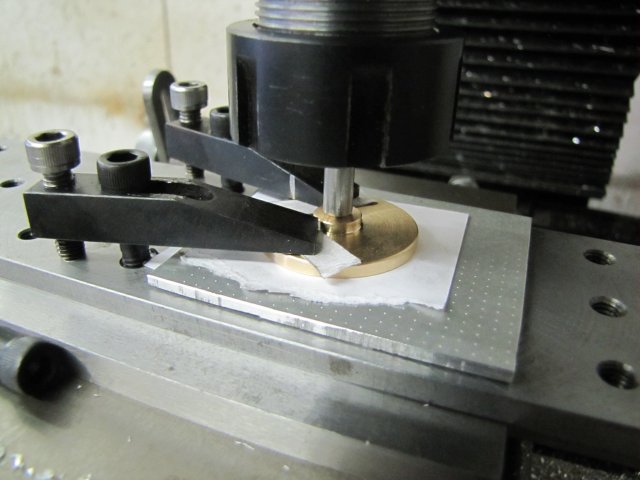
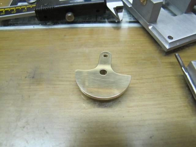
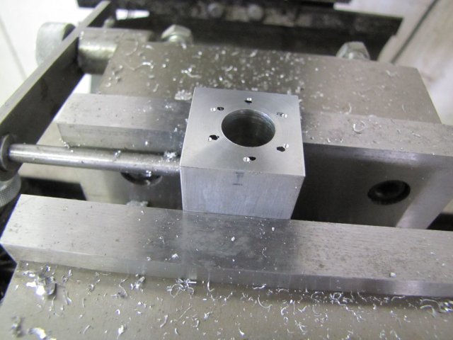
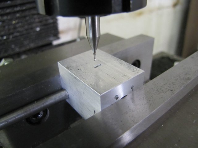
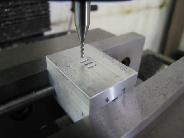
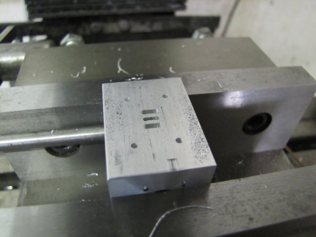
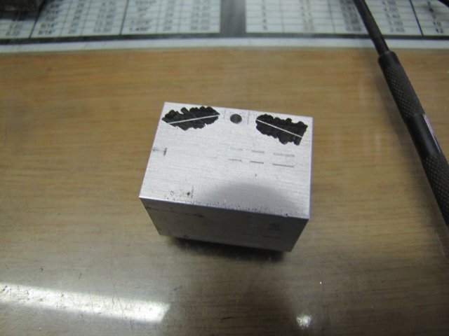
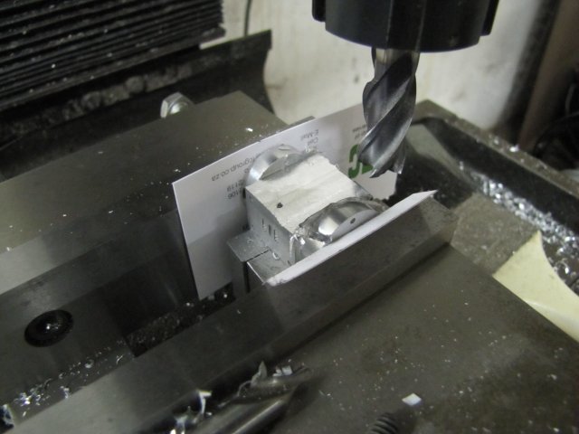
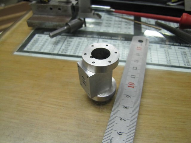
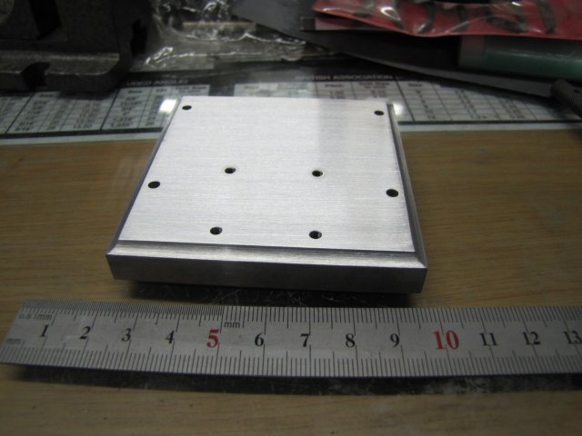
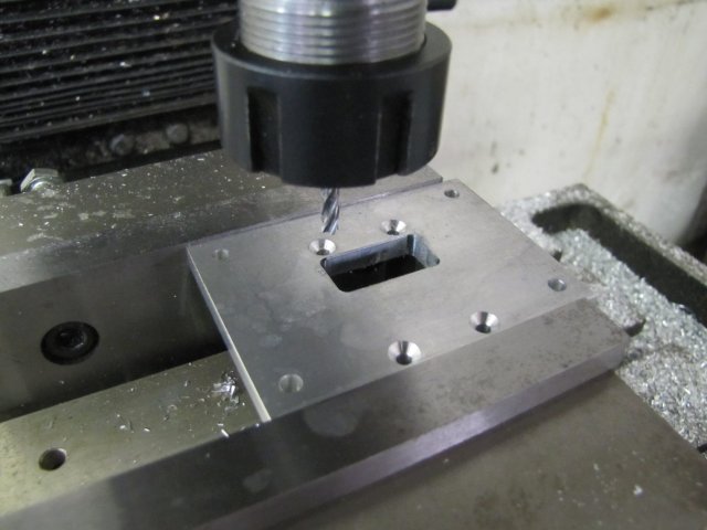
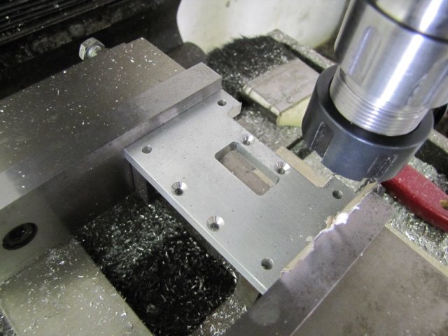
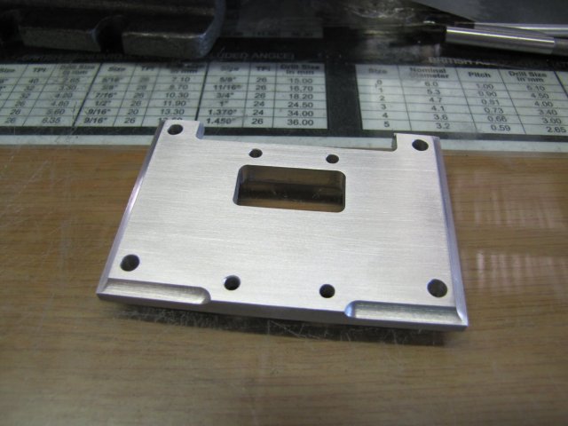
After a bit of decorative milling with a 6mm ball nose mill, tapping the M3 holes where the cylinder will mount, and a bit of elbow grease with riffler files and emery paper to get rid of toolmarks, the base was done with a brushed finish:
We have a long weekend coming up here in Namibia, so I'm going to try and give the engine a good go, but I might divert a bit to attend to a special request I received from a South African member.
Kind regards, Arnold
One of Elmer's would do. The collection of engines on my side-board are growing, but there's a lack of height there, so I settled on Elmer's #32 as a relatively simple engine (compared to the Kimble and Coombers) that has a fair amount of work that can be done on the mill, as well as adding some height to the collection.
I'm not going to go overboard on this build; for the most part I'm going to build it exactly to plans. One exception will be that I'm going to add a slip-eccentric to make it reversible, as this is very easy to add to this engine as a custom touch.
Don't expect too many photos, but if there are any members that would like more detail on certain bits or processes of the build, please ask (publicly, or pop me a personal message), and I'll be happy to accommodate. Any suggestions or criticism is also welcome
I started off with sawing a 78x78x12mm bit of aluminium from a sheet of 12mm plate I have. That was roughly squared up, and then I brought out a bit of kit I have that I've used rarely before - the venerable edge finder. Mine is of slightly dubious quality, and I've never really bothered to set up test equipment on the mill to check it's accuracy and repeatability. Another disadvantage that I had with the edge finder is that it is 5mm in diameter, and my mill's feed screws are 3mm per turn, meaning that in the past I had to be careful about finding an edge and setting the zero-able hand wheel dials correctly to obtain my datum point. So first things first, I tested the edge finder - and much to my surprise it ended up repeatable within 0.005mm (1/5 of a thou) in four out of five tests
- that's much better than I expected, and plenty good enough for my shop; 0.01mm repeatability would be fine with me. With the DRO, backlash becomes a lot less important, and it's easy to set absolute zero.Next I put the DRO to test; I located the right-hand back edge of the workpiece; I tend to work from the right-hand side of the vise as that way I end up with the least amount of chips thrown toward myself while milling, and the fixed end of the vise jaw remains in position on the Y axis. The block of aluminium plate was then properly squared up to size, with the aid of the vise stop.
For the next step, I didn't lay out anything; I simply coordinate drilled four 3mm clearance holes and the small square's 2.5mm tapping holes for M3 using the DRO and incremental readings:
After a bit of decorative milling with a 6mm ball nose mill, tapping the M3 holes where the cylinder will mount, and a bit of elbow grease with riffler files and emery paper to get rid of toolmarks, the base was done with a brushed finish:
We have a long weekend coming up here in Namibia, so I'm going to try and give the engine a good go, but I might divert a bit to attend to a special request I received from a South African member.
Kind regards, Arnold


![DreamPlan Home Design and Landscaping Software Free for Windows [PC Download]](https://m.media-amazon.com/images/I/51kvZH2dVLL._SL500_.jpg)