Edwards Radial 5 Build

Home Model Engine Machinist Forum

Help Support Home Model Engine Machinist Forum:

This site may earn a commission from merchant affiliate links, including eBay, Amazon, and others.
Hi Michael and all,

Unfortunately I have not done any shop time for nearly two months having been away for 1 month and on returning home seem to have had things on and some jobs to do around the house. The good news is they are completed (for now) and I will be back in the shop in the next few days
having a go at making some valve springs.
I am really impressed with your prop boss Michael, it looks fantastic and no spinning off a prop there. Just out of interest I am thinking of drilling and tapping some holes in the front of the cam cover and making a puller to suit in case of the need to dismantle at some stage as there is not much to grip on the cam cover. With the front bearing being an interference fit in the cover and onto the crankshaft it would be a pity to damage it while try trying to dismantle.
Unfortunately I did not take many photo's when making the piston rings but I was able to part them off accurately with a 40 thou. parting tool on the old Hercus (read Southbend). I did find a photo of parting the oil rings however.
I did not have my surface grinder when I made the rings but I think it would a good way to make them as you suggested. It would be easy to do them in a batch and have a lovely finish on the flats. I also made a few spares.
I will keep information flowing as to how I get on with the valve springs. The owner of a local engineering shop has taken an interest in the radial project and is using it to inspire his apprentices. He also has a heat treatment oven and has offered it to me to use to heat treat the springs.

Cheers Brian - Thm:

partoilrings.jpg
 
  • Like
Reactions: xjs
G'day all,
on Sat evening I was at a function and seated opposite me was a gentleman who has a business located at our local airfield. Naturally we started talking aircraft and he informed me there was a 1938 Stinson Reliant in a hanger at the field that had limped in with engine trouble five months ago.
Why don't you come out for a look he said. Nah! I said, not interested can we go now. Good idea he said - but I'm not sure I could afford the divorce settlement he said so why don't you come out Monday. So that's what I did today.
Apparently one cylinder overheated and the motor started spewing oil on the windscreen and misfiring and was lucky to get down in one piece.
This particular Reliant is fitted with a 7 cylinder Wright R760 radial and the engine had to be shipped to the USA for repair. Other versions were also fitted with a Lycoming radial. It is due to be fired up shortly and they are going to let me know so I can go out to the airfield and get high on the radial sound.
I am back into my own Edwards Radial and have successfully made one valve spring but I want to heat treat it before making them all just to be sure all is OK. I will post some pictures when complete.
Meanwhile enjoy the Stinson Reliant Radial pictures.

Cheers Brian :bow:

stinson1 copy.jpg


stinson2 copy.jpg


stinson3 copy.jpg
 
Greetings Brian and each --

That's quite an exotic visitor you have there, Brian. I'm sorry it got sick, but most happy it got down safely. Can I assume they just shipped the faulty cylinder off for repair, or did they send the whole engine? Quite a Fed-Ex bill if that's the case.

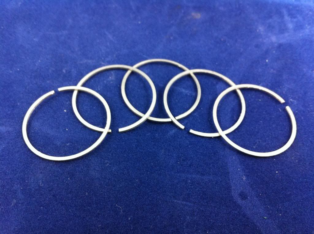
Since last we spoke I think I got the knack of making those piston rings -- here's a pic of the first faultless five, and hoping to knock out twenty or so by the end of the week.

Then, onward to the oil rings (already got a 0.015" slitting saw standing by). After that I'll probably go back and twiddle with my micro-drill-press project a little more before the New Year.

I'm most interested in your valve springs...did it turn out that nothing available commercially was suitable?

Brian, I share your frustration of never having enough shop time. I just got back from a weeklong business trip, and in another three weeks SWMBO and I will be off on our holiday for this year, which will probably last till Christmas. So, any dreams I may once have had about firing up my radial to compete with the firecrackers on New Year's Eve are destined for dust.

No matter. I may not have a radial after a year's work, but I do think I'm a better machinist.

Cheers all...
 
Hi Michael and all,

I'm glad those rings are working out OK now - they look great.
With regards to that Wright Radial I believe the whole engine was shipped back to the States - and yes it would have been a tidy FedEx freight bill. With regards to my valve springs I scoured McMaster-Carr and other websites and couldn't find any at the exact dimensions. In the end I decided to have a go and make them myself. I wound them out of piano wire as per plan on a mandrel in the lathe and set the travel at 10 threads per inch to correctly space the coils. A bit of experimentation was required to get the mandrel diameter right as the spring expanded when the winding pressure was released but all in all they weren't that difficult to make. They were then wrapped in steel wool and then parcelled up with alfoil and heated at 500deg.F for 30 minutes in an oven and then allowed to cool.
I have now assembled all the heads and the valve spring tension feels how I think it should and all the valves appear to be sealing fine. I guess the truth will appear at start up.
See below a bunch of valve springs (the slightly smaller ones are for the oil pump and I made a few spares) and a completed head.

Cheers for now - Brian :hDe:

valvesprings.jpg


headcomplete.jpg
 
Last edited:
They were then wrapped in steel wool and then parcelled up with alfoil and heated at 500deg.F for 30 minutes in an oven and then allowed to cool.

Nice springs. Dumb question but what is role of the steel wool? Do the basic dimensions of the spring change much after heating cycle? I assume this is to stress relieve from the coil winding operation?
 
Hi Brian. One more question about your awesome home-made springs: any special reason because you winded them left hand? Cheers; Moshe.
 
Hi Petertha, - I remembered reading this somewhere in an article on making small springs and I believe the idea of the steel wool is to provide even heat around the springs and also retain some heat and help slow down the cooling process.
You are correct in assuming that the heat treatment process is to relieve stress induced by winding. Piano wire does reduce slightly in size during heat treatment. I wound the springs 15 thou. oversize ID and they finished up pretty much right on the .310 thou. as stipulated in the plans. This was more good luck than good engineering as the only way to come up with what you want is by trial and error.
There is an excellent article on making all sorts of springs here.
http://educypedia.karadimov.info/library/springs.pdf

Cheers Brian
 
Last edited:
Hi Moshe - the reason I wound the springs left handed was so that the jig I made to feed the wire and maintain tension moved away from the lathe chuck thus avoiding the chance of a nasty coming together. Right or left hand compression springs will perform the same. (this does not apply to all springs though). - see link in above post.
Below is a photo of the jig I used - pretty simple.

Cheers Brian

springwinder.jpg
 
Hi Michael and all - I spent most of today closeted in the shop making some dies to punch out some head gaskets. I made an outer die to cut the outside diameter and an inner die that slips inside of the outer die to cut the inner diameter. An arbor press provided the required force to cut the 1/64" gasket material. I machined a piece of nylon for the dies to press against to lessen the chance of damaging the cutting edges.
The outer die is used first and this leaves a wad of gasket material inside then slip in the inner die and cut out the centre wad - and presto - a nice neat gasket and some spares.

Cheers Brian - :idea:

gasketdie1.jpg


gasketdie2.jpg


headgaskets.jpg
 
  • Like
Reactions: xjs
An arbor press provided the required force to cut the 1/64" gasket material.

Hi Brian

- what is the gasket material you have chosen?

- I take it you are using this gasket more as a seal vs. a CR shim & they will be identical across all cylinders?

- I saw on the Edwards drawings that he leaves the cylinder liner top flange a fixed dimension (0.175") with a footnote "note at assembly check compression ratio & adjust to 8.5:1 by trimming top of liner as needed". This finally clicked with me because the Edwards has uncompensated (equal 72 deg) radial divisions for its link rods, so this must be the tweak to match unequal CR's across all cylinders. What I haven't quite figured out is how one would go about doing that with conic topped pistons. Angle the head & fill-up fluid to the glow plug flange, drain & measure cc's maybe? I'd like to hear your thoughts on this because it always puzzled me.

thx/Peter
 
Gobsmacked. Simply gobsmacked.

Some time, in a thousand years or so, once I've managed to bring some cylinder heads like yours into being, I shall refer back to this example of how Proper head gaskets should be made, so they'll have something comfy to sit upon.

Well done that man.

m
 
Hi Peter - the gasket material I got from Omni Models described as a heat resistant rubberised compound and I am using it hopefully to provide a perfect seal between barrel and head.
There are plenty of online tools to help calculate compression ratio.
On the Edwards The piston dome and combustion chamber have the same geometry except for a small 20 thou. step under the conical combustion chamber. A compression ratio calculator takes into account the total volume of the combustion chamber, the volume of the piston cone and the slight cavity under the gloplug can be added in if you want to be absolutely accurate. All volume calculations are either the volume of a cone or a cylinder - plenty of online calculators to help with as well. The thickness of the head gasket (compressed) is also taken into account. Of course bore and stroke are also entered.
By entering a figure for the piston edge to deck level (top of cylinder) a compression ratio will be calculated. It is easy enough to "fiddle" with this number to arrive at the desired compression ratio - in the Edwards case 8.5 to 1.
Once the piston edge to deck measurement is known each cylinder can be measured at TDC from the top of the piston cone to the top of the deck (barrel)
and this measurement is then deducted from 172 thou. which is the height of the piston cone. For example if 60 thou. of the piston was above the barrel the piston to deck measurement would be 112 thou. and if the calculated piston to deck clearance was say 80 thou. an amount of 32 thou. would need to be machined from the top of the barrel. In fact it looks like an 80 thou. piston to deck clearance will be around the mark.
Repeat procedure for the other four cylinders to obtain an even compression ratio on all cylinders.
I don't know if I have explained this very well but have a look here and have a play with the compression ratio calculator as I think this will be a big help.
http://www.csgnetwork.com/compcalc.html

Cheers Brian :wall:
 
The piston dome and combustion chamber have the same geometry...

Ah, of course. The matching domed piston/chamber profiles simply things. Ive made this out to be more complicated than need be. Carry on! :D

Its interesting how different designers went about addressing this issue. Some tweak the link rod geometry on the master rod & try & keep the cylinder lengths the same. Other engines reduce the combustion bowl footprint over the piston (to raise CR). The Edwards piston dome within a dome is yet another method. Maybe other advantage is lining up with valve action axis without intefering with (flat) piston top.
 
G'day Michael/Peter and all,

the closer I have got to assembly the more I became worried about disassembly particularly the cam cover as this is bound to be required sooner or later. The cam cover has a bearing in the front that is an interference fit in the cam cover and onto the crankshaft and I could see no way of getting it off again without the risk of damaging it. If the crankshaft was pressed out of the engine from the front an interference fit on three other bearings comes into play - two on the cam disc and the rear crank bearing.
I have spent the day coming up with a solution - drill and tap the front flange of the cam cover and make a puller that bolts on and and the pointed end of the bolt presses into the centre drilled recess on the end of the crankshaft applying (hopefully) enough force to pull the cam cover with bearing off of the crankshaft.
I think the photo's are probably self explanatory.
The next job is to assemble crank, rods, barrels and pistons (without rings at this stage) and measure piston to deck height and machine the tops of the barrels as required to give an equal compression ratio of 8.5 to 1 on all five cylinders. I will report as to how this process pans out.
I am looking forward to seeing your mini drill press Michael - that should be a real handy bit of kit. A lot less "clunky" than using the mill or a large drill press when you are working on mostly small parts.

Cheers Brian :idea:

drilledcamcover.jpg


puller.jpg


camcoverpuller.jpg
 
  • Like
Reactions: xjs
That's a peach of a puller, Brian, and I think I need to come up with an excuse to make one. It hadn't occurred to me before...I've had the cam cover and bearings and crankshaft assembled and disassembled a few times now (great therapy) without incident...though now I've begun to wonder if, after a few thousand air miles have been clocked, things might get a bit stickier. And the thought of having to pry this particular motor apart with a hammer and screwdriver makes me come over all wobbly.

Meanwhile, I'm happy to report a full double-stock of compression rings and oil rings. Many more than I hope I'll ever need. (Although a proper Hoard of the Rings, perhaps?) They were a great deal of fun to make, but I'll be happy not to be dealing with cast iron for a while. You were right...it's a delight to machine, but the dust gets everywhere.

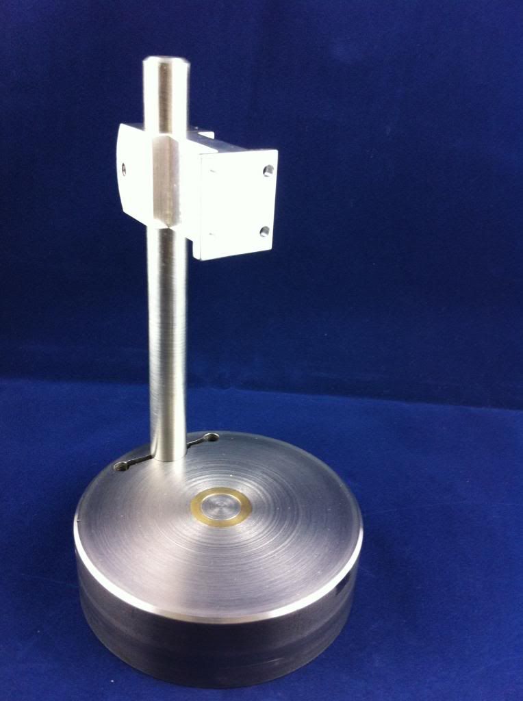
That success seemed to merit a couple of hours working on my little Howell drill press as a reward. (Funny how as you get older your guilty pleasures get less, well, dramatic...). Here's a pic of progress so far:


Sorry about the glare, the pic was taken as a hurried afterthought as I was running to be somewhere else.

That mild steel base ( about an inch thick) contains an electromagnet (complete now except for the winding), and is the reason for the brass sleeve in the middle. So I'll finally have my very own magnetic chuck. And I just took delivery of an exquisite little Albrecht drill chuck...0"-1/16"...for the business end. Beautiful thing.

Just a couple more days left before we take off for a drinking and dancing interlude over on the Other Side, so the Radial will be tucked up for a little while.

All best everyone...

m
 
Hi everyone - have a Merry Christmas and a safe and prosperous 2014 littered with new engine projects.
The Edwards Radial is assembled with only the inlets and exhausts to do.
All appears OK and will update in the New Year.

Peace and Goodwill - Brian *beer*
 
Hi Brian, I have been quietly following along, the build is outstanding. I already seem to have enough projects to fill up next year, anyhow, Merry Christmas and have a great New Year. I am looking forward to more posts in the new year.

Paul.
 
Hi Michael and all - Happy New Year and good modelling in 2014.

I only got back into the workshop a couple of days ago after the Xmas - New Year festivities and decided to tackle the dreaded brass tube bending required for the exhausts and inlets. I decided to do the exhausts first to practice on as they require a simple half inch radius right angle bend where as the inlet tubes require two precise bends to fit between the heads and inlet manifold. I followed some instructions found on the net and have to admit that I am more than pleased with the end results and am now confident of doing the inlet tubes. In fact I now reckon the fifteen mounting flanges will be the fiddliest part.Web page here - thanks guys http://www.hitechalloys.com/hitechalloys_005.htm
This is the procedure I followed :

1. Cut brass tube to length and heat a dull red and quench in cold water to anneal.
2. Plug one end of brass tube (I turned up a small slightly tapered wooden plug).
3. Fill tube with cooking oil (I used olive oil) then drain out. This leaves inside of tube lubricated.
4. Melt a small quantity of Woods Metal (I did this in a beaker in a bath of boiling water heated on a small gas burner).
5. Place a small funnel (I made one for the purpose) into the open end of the brass tube and pour in the molten Woods Metal.
6. Now this is the really important part. Immediately plunge the tube into cold water (I placed a few ice cubes in the water to chill it down) to anneal the woods metal. Apparently if you do not do this the Woods Metal solidifies with a coarse brittle granular structure and breaks when trying to bend it.
7. Clamp the tubing in the tube bender I made previously (see in an earlier post page 12)
and make the required bend. The tube bent smoothly with very little force required and to my delight almost no distortion.
8. Finally place tube in boiling water to melt out the Woods Metal. While still hot I pulled through a small piece of wet rag hooked on the end of a length of thin piano wire to remove any droplets of Woods metal remaining in the tube. On cooling the Woods Metal can be reclaimed to use again.

And dah - dah - see results in photo.

PS. I will not be venturing into the shop in the next few days despite it being air-conditioned as we are currently experiencing a heatwave with with temperatures of 46 deg.C or 115 deg.F. - forecast is for cooler by the weekend.

Cheers for now - I"m off to *beer*

exhaust bends copy.jpg
 
Hi all,
I recently received a private message from HMEM member lantain1982 who had been following our Edwards Radial builds enquiring if I may like to contact him as he had a similar interest in model internal combustion engines . It turned out he only lived about an hour away so we promptly made arrangements for me to visit his workshop. I spent a very interesting morning with a tour of his very well equipped worship and much chat about various engineering aspects but the highlight was to see and hear running his beautifully engineered Bentley rotary engine - similar to a radial but the whole engine rotates while the crankshaft stays still. To see those nine cylinders whirling around and the radial like sound was a wonder to behold.
With lantain82's permission I have posted a couple of pictures of his Bentley.

Cheers all and thanks to lantain82 :bow:

bentley1 copy.jpg


bentley2.jpg
 
  • Like
Reactions: xjs
Back
Top