Double-Cross. Elmer's #34 Cross Twin Engine

Home Model Engine Machinist Forum

Help Support Home Model Engine Machinist Forum:

This site may earn a commission from merchant affiliate links, including eBay, Amazon, and others.

Sshire

Well-Known Member
Joined
Jun 29, 2011
Messages
935
Reaction score
267
Double-Cross
Elmer’s #34 - Cross Twin Engine
Part 1


Other than polishing, the Liney RV-2 is done. So, here we go with the next engine.
I’ve always wanted to do a horizontal engine and Elmer’s #34 - Cross Twin Engine seemed intriguing.
After reading the drawings, so that I understand how the engine works, I called my neighbor, Fred, who has a virgin copy of the actual Elmer’s Engine book. The John-Tom drawings are fine but the pictures look like the result of someone who has a $3.00 scanner and has no idea how to use it. As far as I could tell, the picture was either an engine or a Koala in heat. Having the book, with Elmer’s very clear pictures, is a major help.

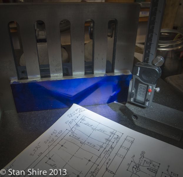
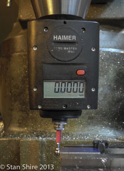
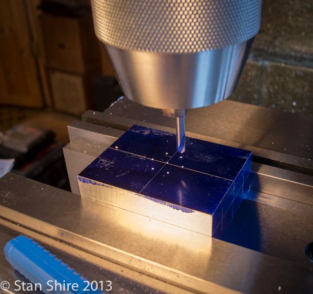
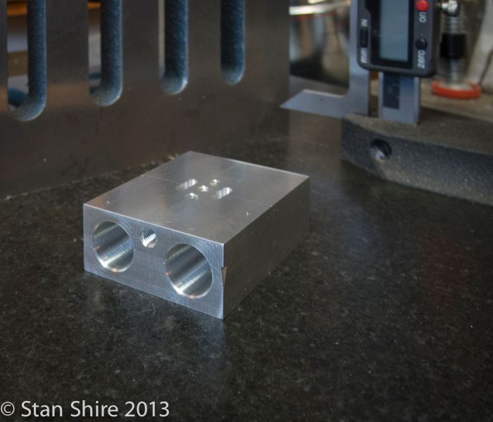
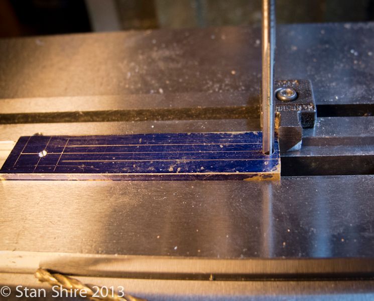
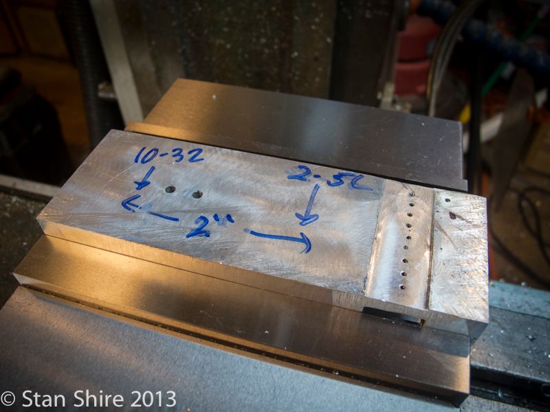
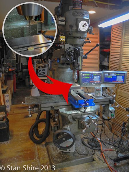
I started with the base. 6061 aluminum plate. My normal procedure is to mark the piece as a “sanity check” with the DRO.


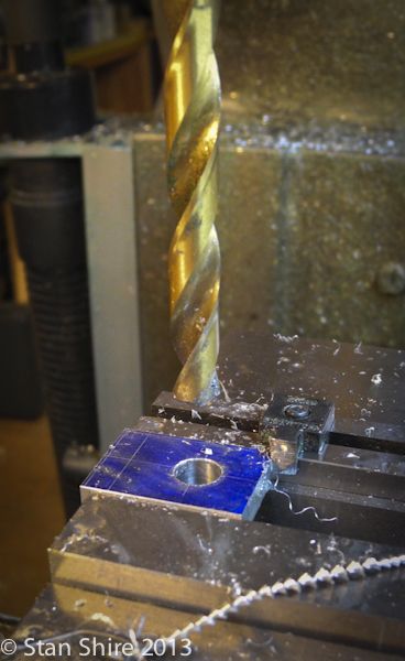
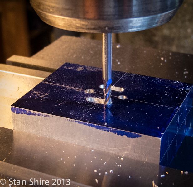
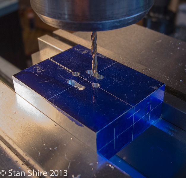
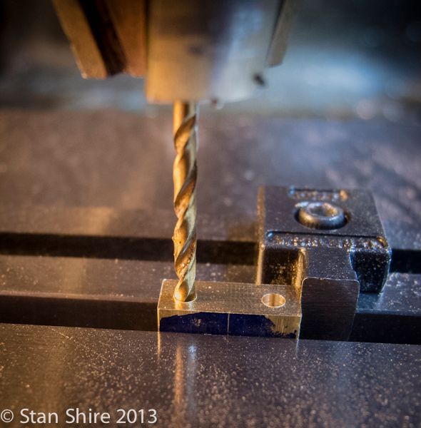
After cutting a rough-size piece, squaring and sizing it from the 3/8” 6061 plate, spot drilling, drilling and tapping commenced.
All holes were put in as SDM (sub data memory) in the DRO. This way I can do all spot drilling, then all drilling, then all tapping just by going to the 10 sub-data points.
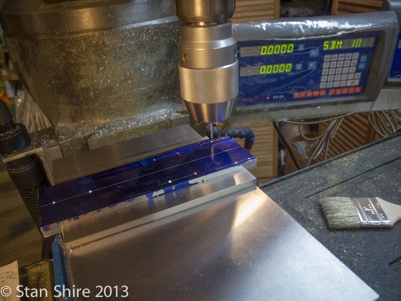


When that was all finished, I flipped the piece over and did the counterbores.
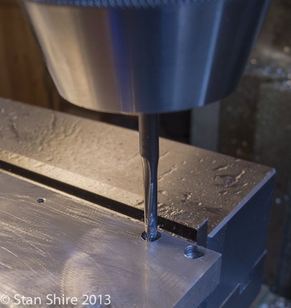


And done.
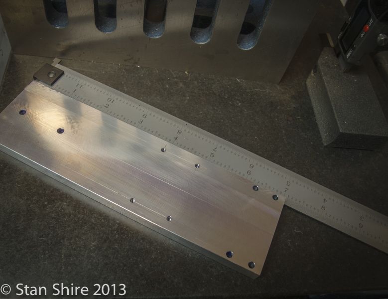


I’m going to do the bearing block next. The RV-2 was the first engine that I had done with bearings. I’m a believer! I’ve got some extra .25 ID Boca Bearings from the RV-2 build.

So here’s the question.
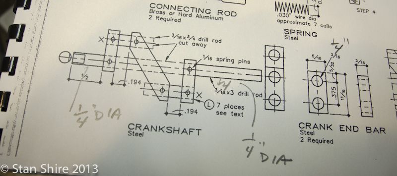
Is there any reason that I shouldn’t (or can’t) increase the crankshaft ends to .25 (to fit the bearings) from Elmer’s .1875?
There seems to be plenty of metal available in the bearing block for this increase.
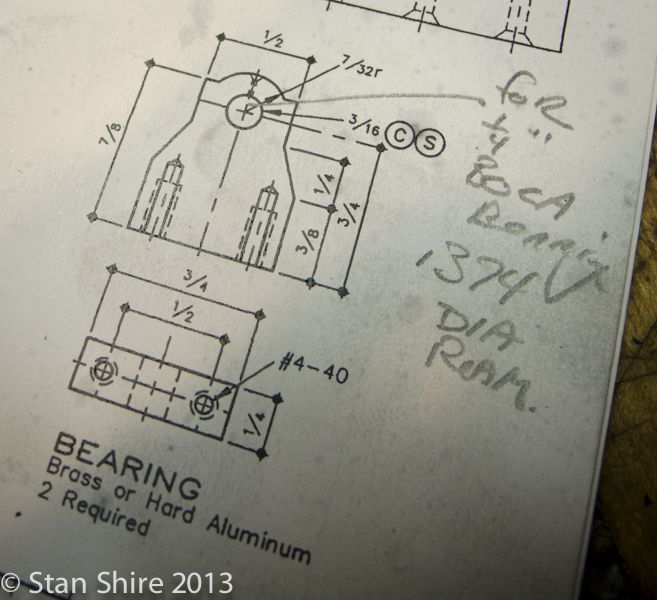


My thought is to only increase the crankshaft ends and leave the middle at .1875.
 
I'm looking forward to another great build log. Great documentation!
I'm hoping to get more shop time now that winter is here. I have so many works in progress I'm not sure where to start! :eek:
cheepo45
 
Stan,
No problem increasing the shaft to 1/4 and using bearings. You will be getting a little thin on the top of the bearing stand (1/32) but that is acceptable. Because the step to form the simulated bearing cap on the top of the stand I just made the stand 7/16 wide and rounded the top. In your case I would make it 1/2 wide as per the drawing and put a 1/4 inch radius on top. This will make the stand 1/32 taller.

The only other change that I remember was I made ball joints for the valve rod linkage. Mostly because I was into making ball ends at the time. I just pulled mine out of the display case to look at. I generally put the completion date on my models and it was dated 1990. Hard to believe it's been 23 years.

If you need photos of any details on mine I can shoot them and email them to you.

Gail in NM
 
Scott
Start anyplace. Make an engine.

Gail
I'm fascinated by the ball joint concept. Pictures would be great and I'd love to know how you machined them.
I had planned to slightly increase the bearing stands to allow for a bit more metal on top.
 
Stan,
The valve linkage is a design flaw on #34. The actions at each end are at right angles to each other and move at fairly large angles. If the pins at each end are made a close fit then the valve link must bend. If the holes at each end are oversize so no binding occurs then there is a lot of slop when the valve is in mid position. Neither was acceptable to me so I built ball joints for each end.

I found the old drawings and made up a couple today. So as to not dilute your thread I will post a tutorial on building them in a new thread. Should get it done tomorrow or the next day. I shot the photos today and cleaned up the drawings some.

Gail in NM
 
That's great, Gail. Looking forward to it.
 
Double-Cross
Elmer’s #34 - Cross Twin Engine
Part 2


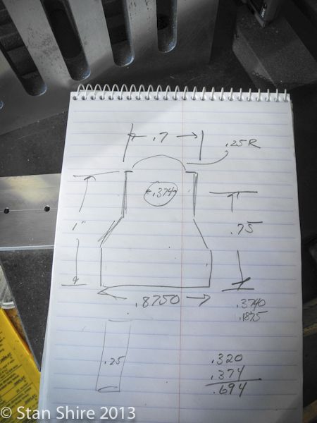
In order to use the .250 ID bearings, I slightly changed the dimensions of the bearing blocks.
Here’s the CoC.


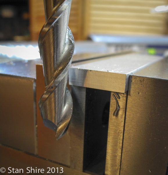
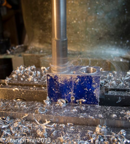
Squared up and sized the 6061 for the blocks. I’m liking the finish on aluminum and brass with this high helix end mill.


The two blanks for the bearing blocks ready for drilling and milling.


Centered and the edge zeroed.


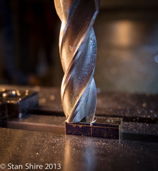
I’ve drilled 11/32 (.3437) to make sure that the line reaming for the bearing OD (bearing specs say ream to .374) will be accurate.


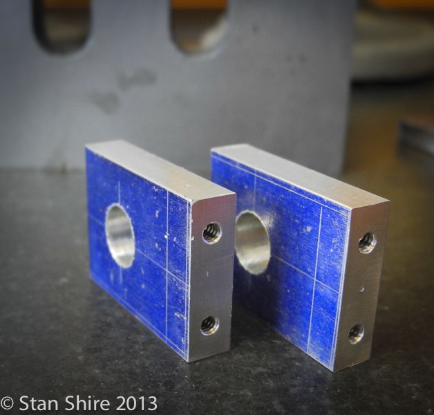
Holes all drilled for the bearings and 4-40 threaded holes for the mounting screws.


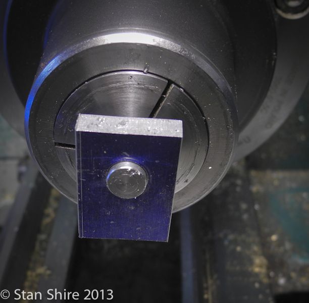
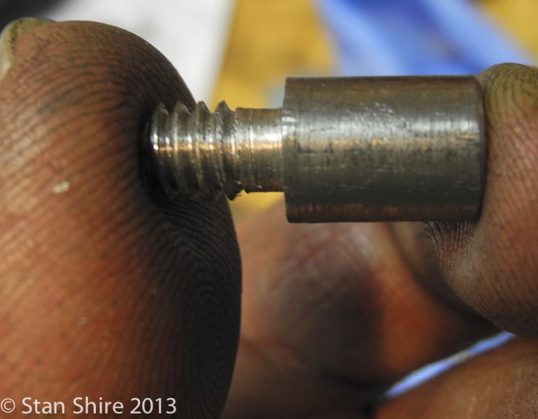
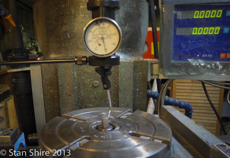
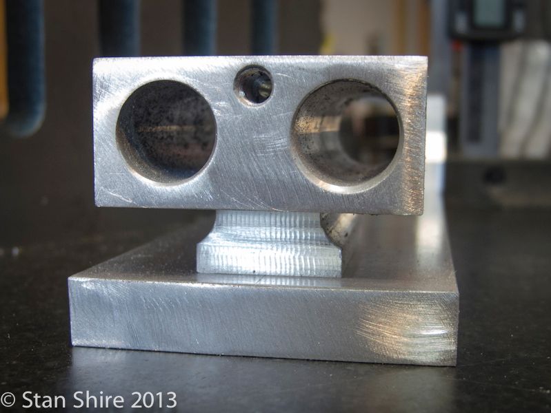
I threaded and turned a locating pin for the ¼-20 center hole in the rotary table. Checking the bearing block for a good fit.


And the out-of-focus finished pin.


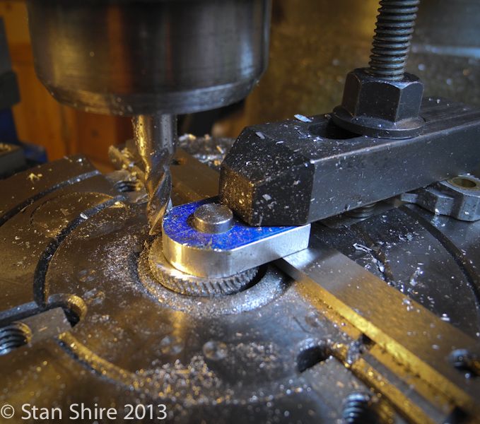
With the locating pin threaded into the rotary table, a quick centering and ready for milling.


Crank the rotary table to round the end.


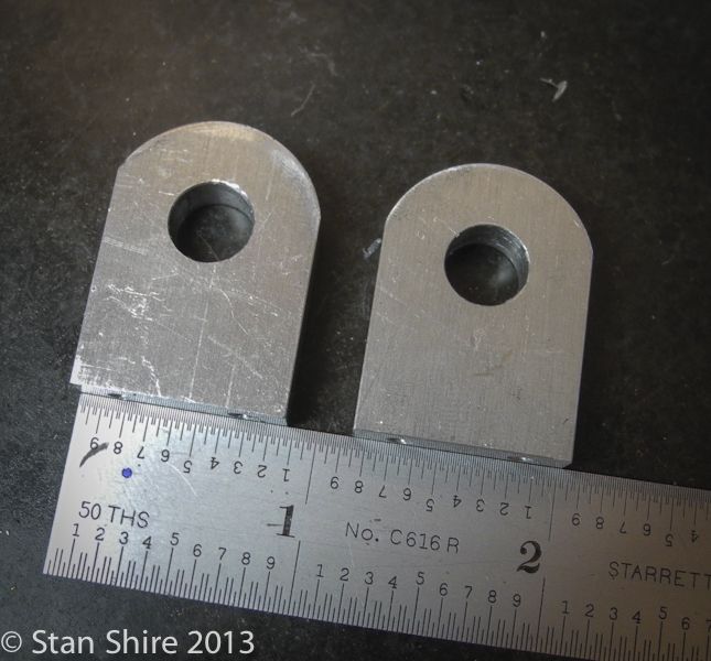
And, two blocks.


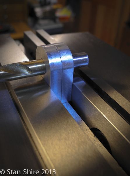
I’m using the 11/32” drill bit to align the two blocks for milling.


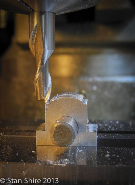
The top flats


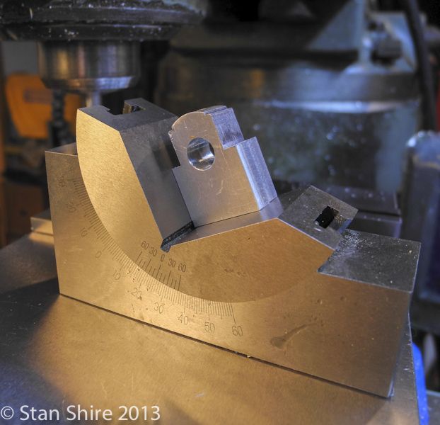
And the side angle setup


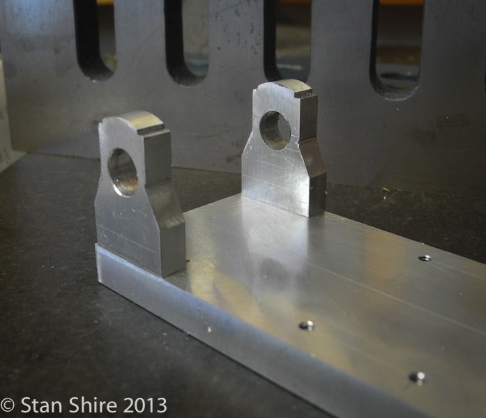
With the milling done, the bearing blocks are screwed to the base.


And line reamed


That's today's parts. I'm trying for a part a day.
 
Stan: Impressive as always. Pulling up my chair to follow along. Roger
 
Double-Cross
Elmer’s #34 - Cross Twin Engine
Part 3

Here’s your part for the day, the cylinder block.

After staring at the drawing and calculating hole depths (which Elmer, for unknown reasons, neglected to include), metal removal began.
As with most of there parts, I did a layout just to stop myself from making some unrecoverable error. These usually happen on the last op of 426.

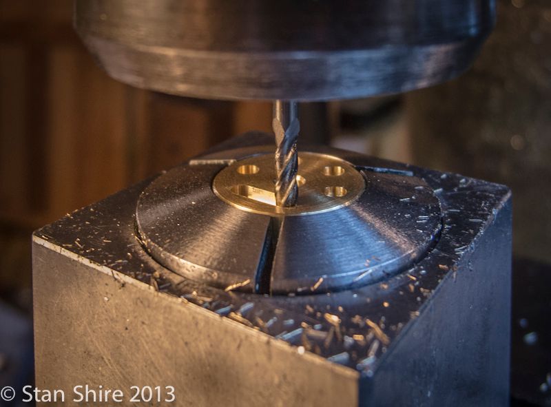
Entering the data for the 6-hole, 0.5” diameter circle into the DRO, I lightly tapped the spotting drill just to be sure all was correct. That done, I spot drilled the 6 holes.


The upper and lower pairs are connected with an air-passage; 3/32 end mill at a depth 0f 80 thou.


Then 3/32 holes, centered on the air-passages. These will exit in the center of each cylinder. The end holes, also 3/32”, are intake and exhaust.


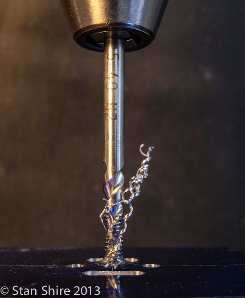
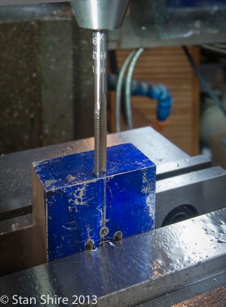
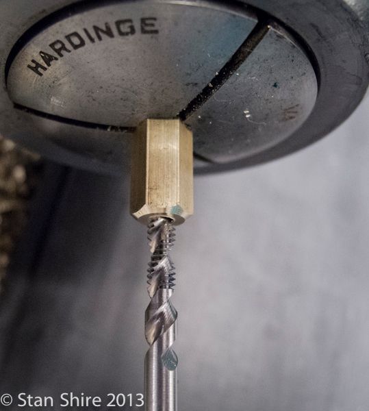
I’ve been using spiral flute and form taps for smaller holes. Much less possibility of breaking a tap. You can see how the spiral flute pulls the chip out of the hole. This hole, which is tapped 5-40, is for the screw to fix the valve to the cylinder block.


Now to the end of the block. This hole, and its mate at the other end, are the intake and exhaust and intersect the holes at the top of the block. It’s first drilled .88 deep (3/32” again) then counterbored .300 deep for the intake pipe thread.


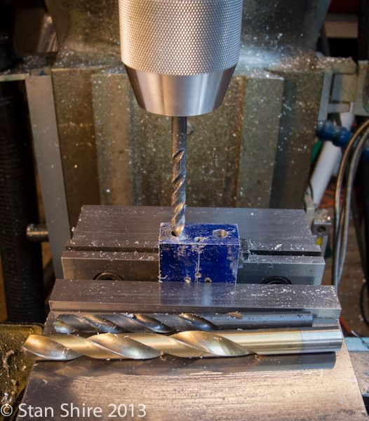
Now some step drilling to get the cylinders just under 0.500. The hole is 2.125” deep.


Reaming to 0.500. I’ve been using the knee power feed for boring and reaming and getting a nice finish.


An almost-finished cylinder block. Two mounting holes to be drilled in the bottom. The small triangular notch at the front corner was to keep my orientation correct as the block was flipped.Another sanity check which will disappear when the chamfers and finishing are done.


Tomorrow’s parts should be the support foot that goes under the cylinder and the valve. I’m waiting for the Brown truck to show up with the .125 brass balls and an 0-80 form tap so that I can work on Gail’s microscopic ball joint technique.
 
Stan
I have followed two of your other builds and may I say you do excellent work.
Well except for that one part you that messed up on the water pump, but that build turned out to be museum quality. I'll be tracking this one.

Art
 
Thanks, Art. You obviously missed the upside-down PM Research Horizontal boiler build. Its a classic screwup. Don't miss it.
 
Double-Cross
Elmer’s #34 - Cross Twin Engine
Part 4


Today’s activities were the cylinder foot and valve.

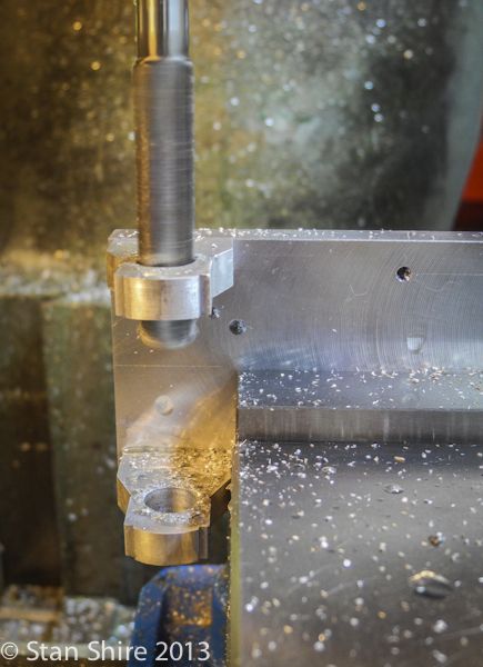
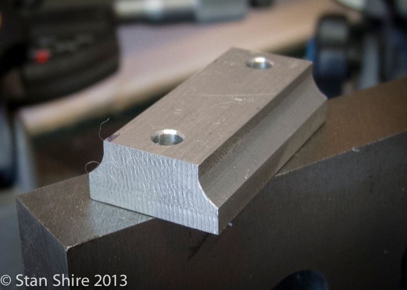
I thought a bit of profiling would make the rectangular foot better visually.
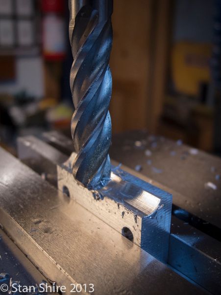
After squaring up the part and drilling the clearance holes, a ball nose end mill, flip the part, another pass and a part is done.


A test fit. I’m happy with the profiling. Filing and sanding will come later.


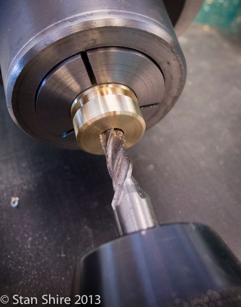
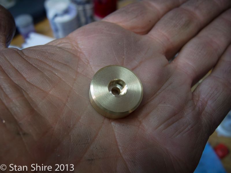
Now the valve. A .125” through hole and this .250” counterbore.


Beveled and parted off.


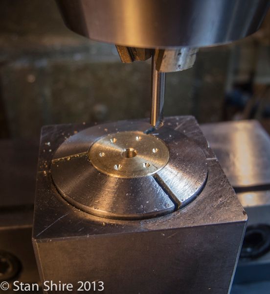
The part goes back into the collet and collet block for a trip to the mill. The bolt hole circle is identical to the one on the top of the cylinder.


Milling the connecting passages.


With that completed, it was back to the lathe to make a nut to hold the valve to the cylinder top.
I couldn’t seem to find the correct specs in Machinery’s Handbook for a 5-40 nut. It must be there and if someone can point me to nut specs smaller than ¼”, I’d be grateful. Im using the spiral flute tap again.


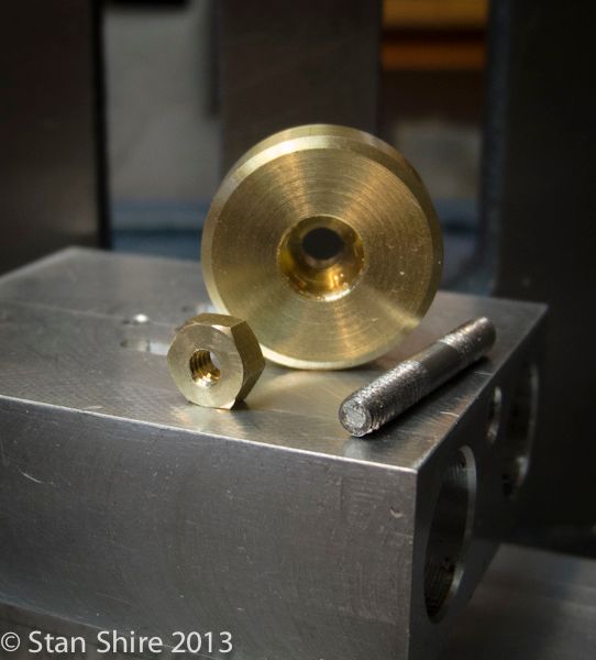
Valve, stud and nut. I’m not happy within the nut beveling so it will be remade.


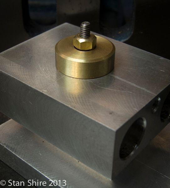
And in position.


One part a day. Sometimes two. Sometimes the same part remade.
 
Great progress Stan, looking forward to the next update :)
 
Stan: Looks good. Pulling up a chair. Thanks for posting your build. Roger
 
Double-Cross
Elmer’s #34 - Cross Twin Engine
Part 5


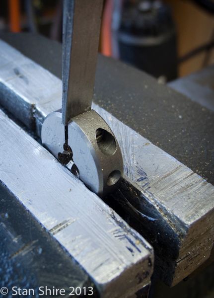
After the annoying morning with the 4-40 die I switched to the con rods.
(if you missed the die episode, here it is)
http://www.modelenginemaker.com/index.php/topic,2908.msg50123.html#msg50123

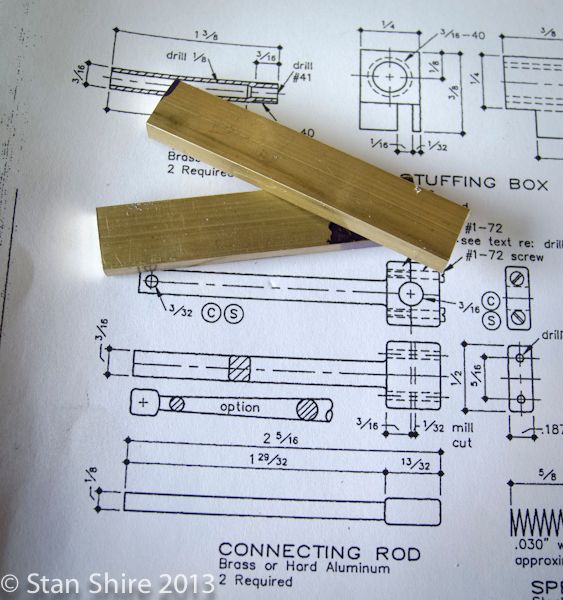
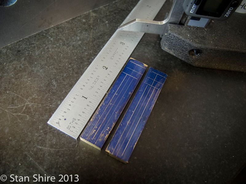
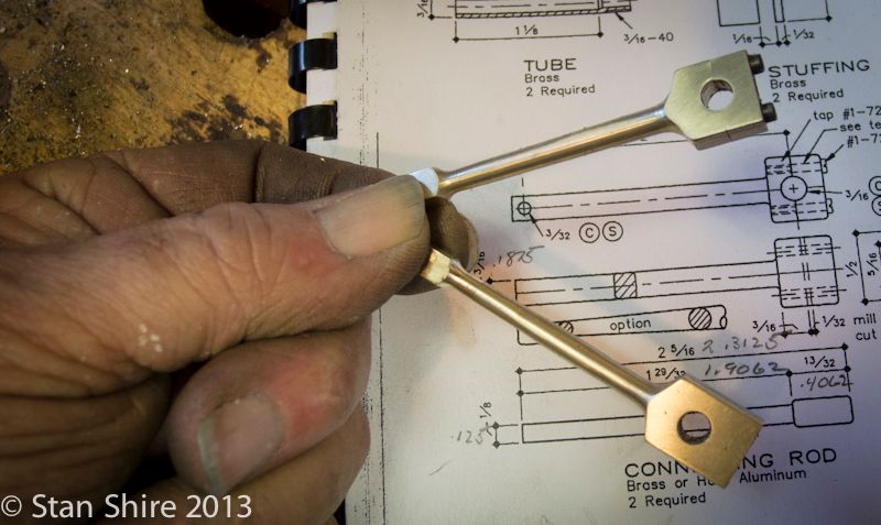
Two pieces, rough cut. Elmer suggests tapered con rods as an alternative. I’ve never (intentionally) turned a taper but Bogs once told me if you never try something, you’ll never know if you can do it.
Why not. It’s only a bit of brass. My usual procedure is to think about how I’ll hold a part and I think I have an idea on that one.


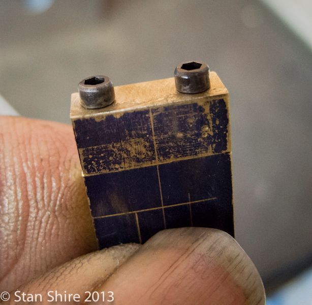
The usual marking out as a double-check against the DRO.


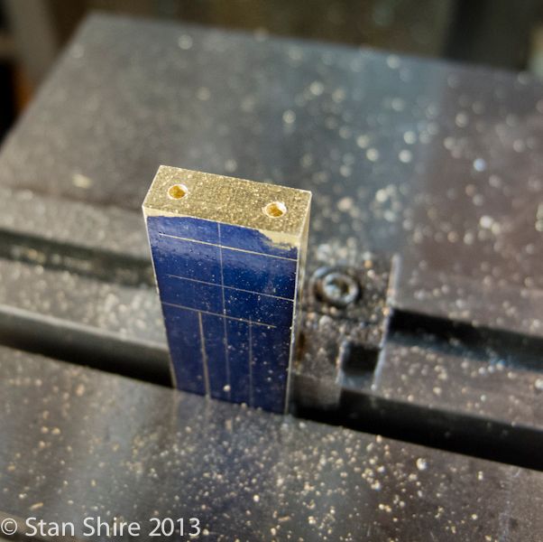
Drill 2-56 tapping size hole.


Then the .02” slitting saw to split the part.


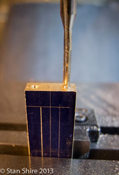
The bottom gets its 2-56 threads.


And the top (which was cut off) gets its clearance holes.


Then milled to final length and reattached.


I decided to make a third “practice” conrod to allow for a screwup on the taper turning.


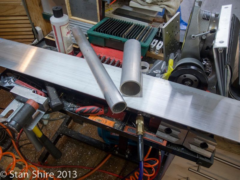
I mentioned in the previous post of this build, that I needed a 2”x3” piece of .125” thick aluminum for the crosshead guides. Nary a piece of .125 lurking anywhere.
After the trip to “Fazzio’s Steel and Metal Supply” (I’m always confused by the name. Thought steel was a metal but who am I to argue with the Great and Powerful Fazzio?), I returned home with this. Four feet should cover any screw-ups on the 2”x3” part. The tubes are going to become holders for the air ratchet and die grinder.


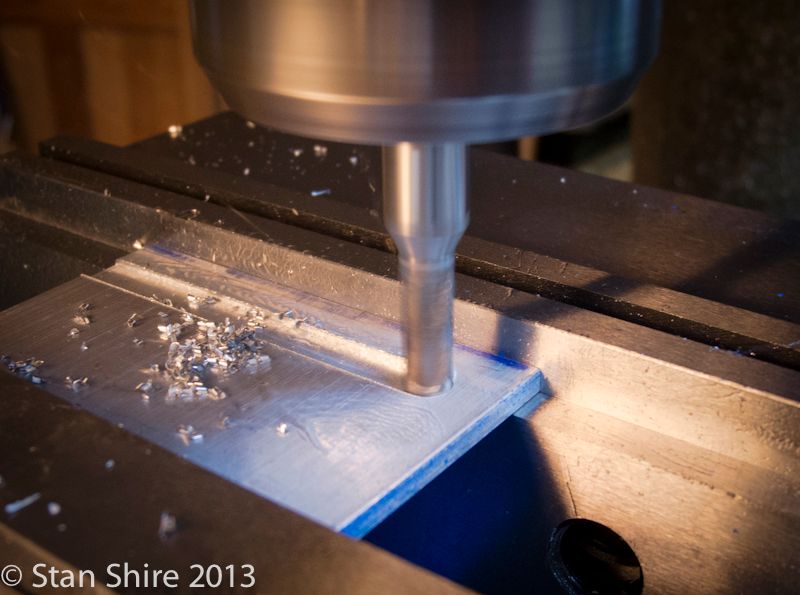
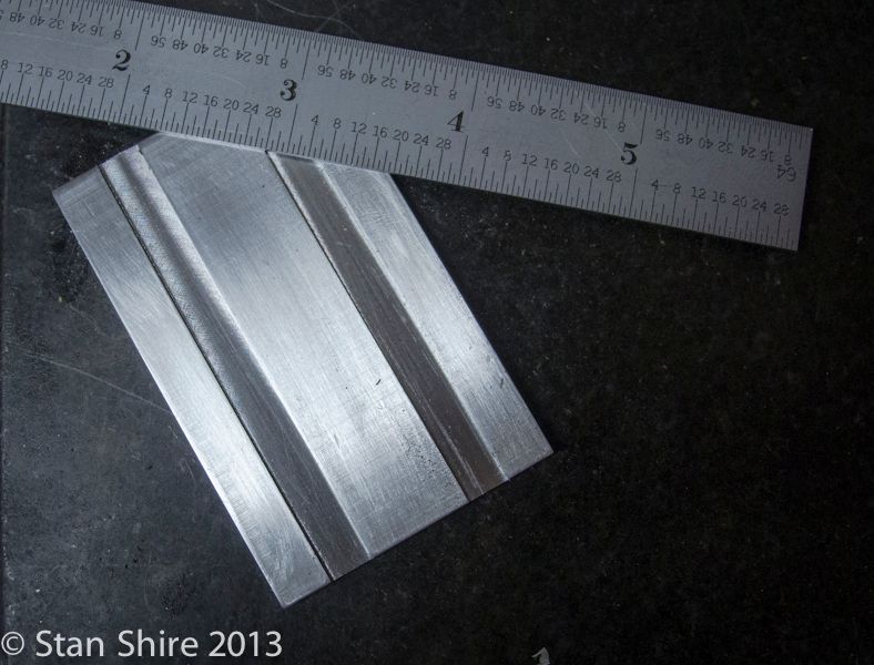
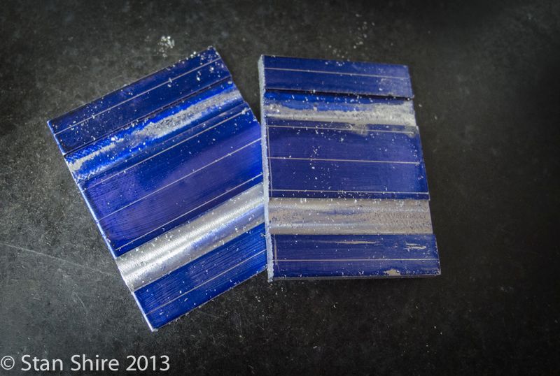
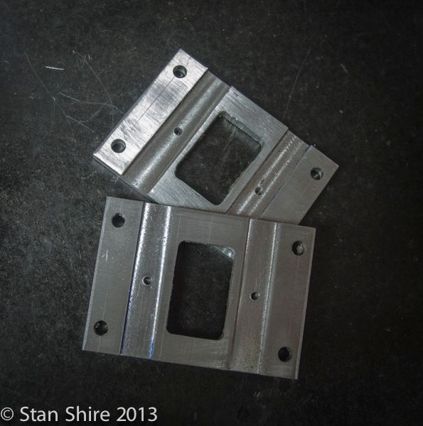
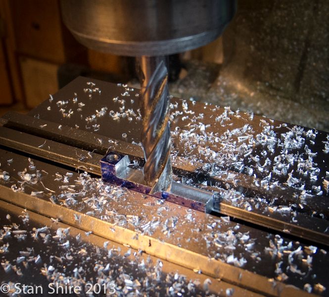
The crosshead guides get two .25” channels for the crossheads.


Then marked out for drilling.


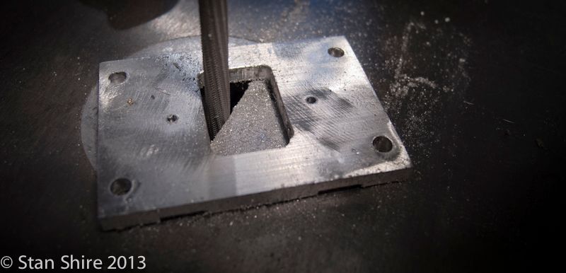
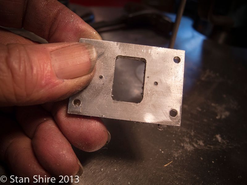
In machining the opening in the crosshead guides, I didn’t make it back to 0,0 on the lower right corner. Oliver, fitted with a thin chainsaw file, fixed that.


Other than a bit of fettling and polishing, these are done.


Now, back to the tapered con rods.

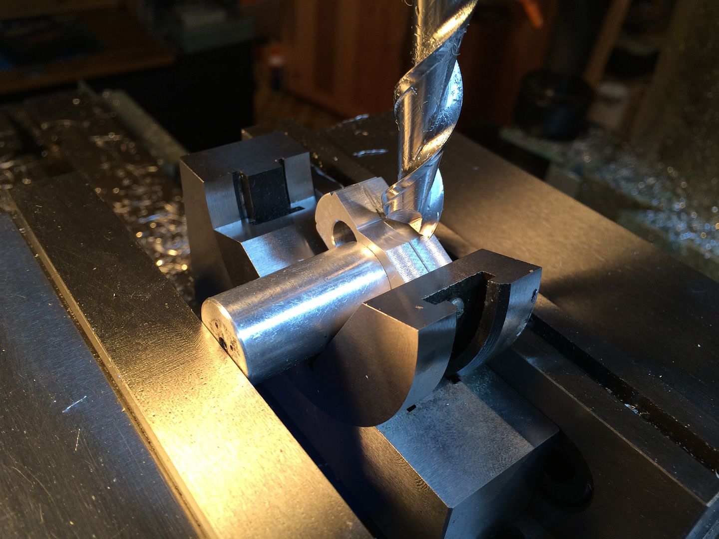
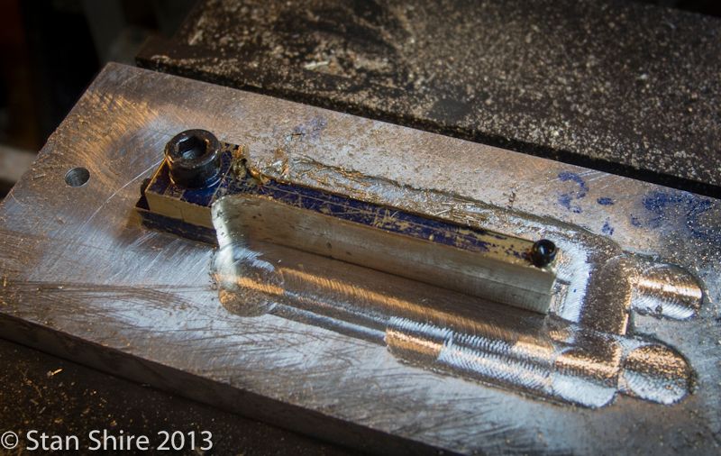
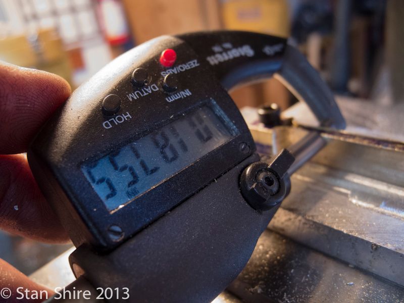
Making a fixture to hold the rods to mill the narrow part to .1875 width. Since the rods already have holes, it wasn’t a stretch to do it this way.


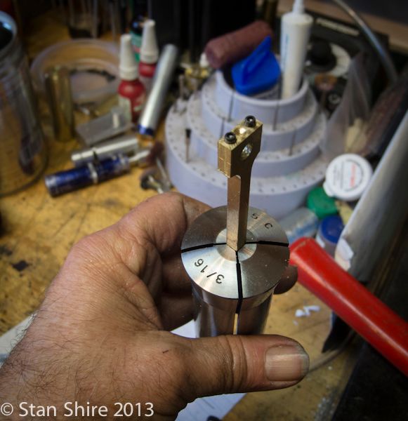
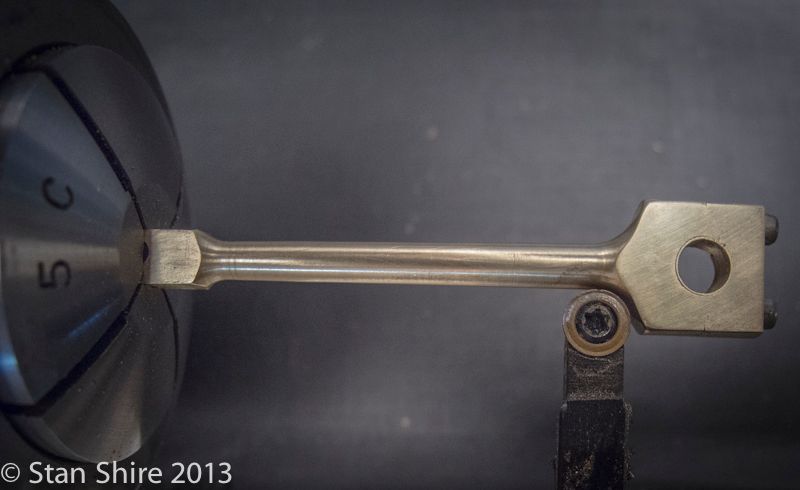
Now, the rods fit in a 3/16” 5C collet.


No 4-jaw; no indicating. Worked as I had envisioned.


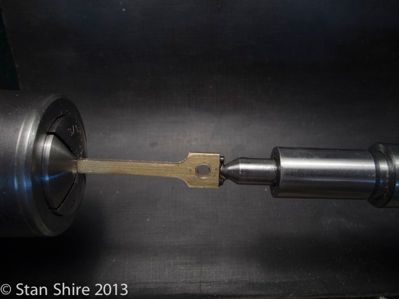
Elmer suggested setting the compound at 1.5 degrees for the taper. Done.


One completed. One to go.


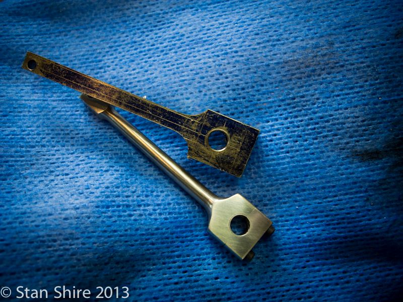
A pair. The one without the screws was the test conrod.


Haven’t decided what part to start tomorrow, but, Im leaning toward the crankshaft. I’ve an idea for assembling and taper-pinning the crankshaft which will require constructing another fixture.
Stay tuned.
 
Double-Cross
Elmer’s #34 - Cross Twin Engine
Part 6


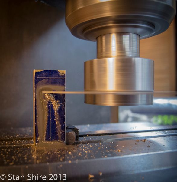
Here’s the round carbide insert cutter. It’s something I heard about from Bogs. When it gets dull (not likely with the amount of aluminum and brass I cut with it) the insert is rotated a few degrees and you're cutting again. Cuts left and right and makes nice curves at the ends.


Now, a short break while I make a tool to make a tool (Klotz Level 2).

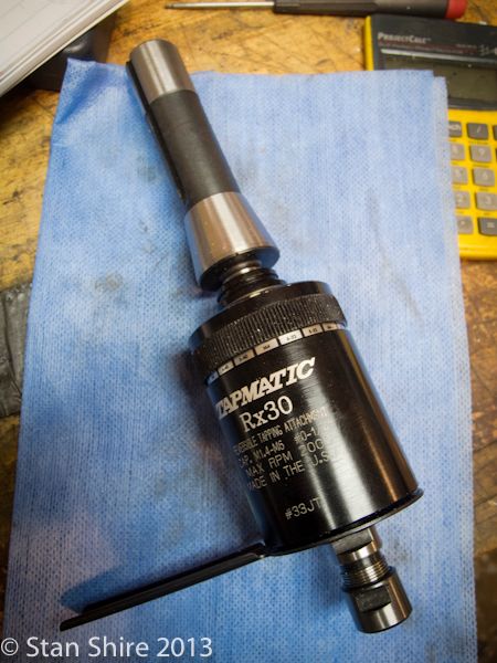
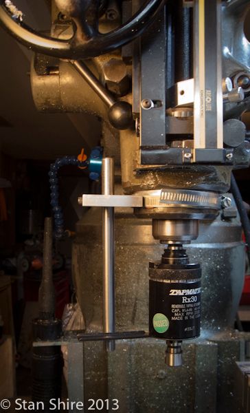
Every time I use the tapping head, I’m setting up mag bases and strange setups with T-nuts and threaded rod to keep the Tapmatic’s arm in position. And, everytime I do this, I swear I’m going to make a proper “torque arm stop.”


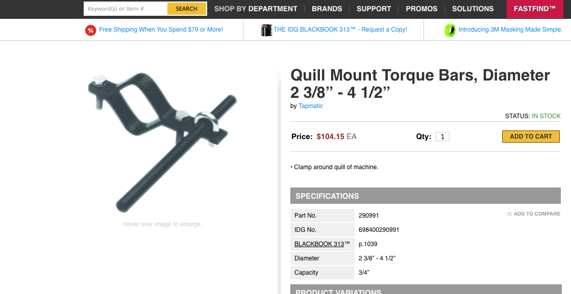
I did look at Tapmatic’s device that clamps onto the quill. I couldn’t imagine anyone buying this, given that they just might have a machine shop.


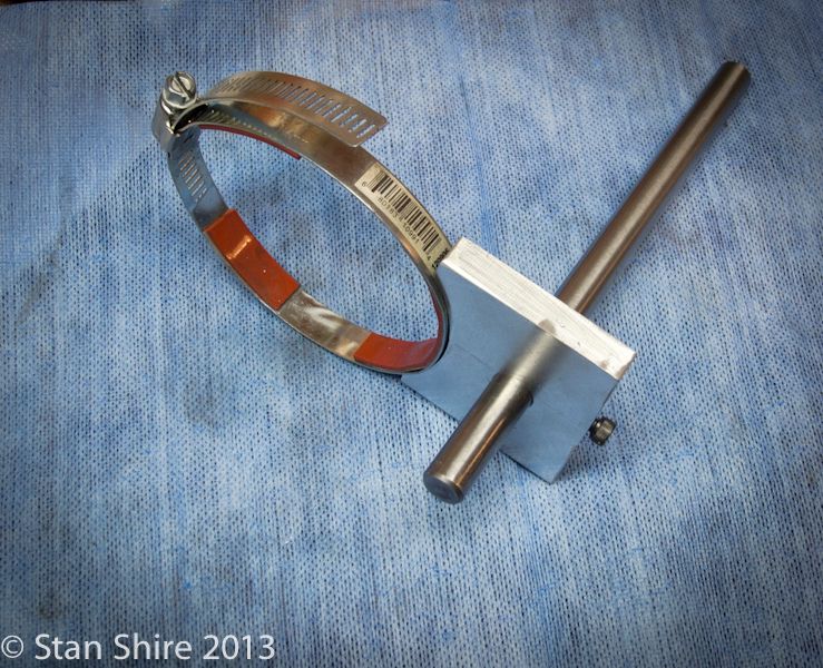
So I made this.


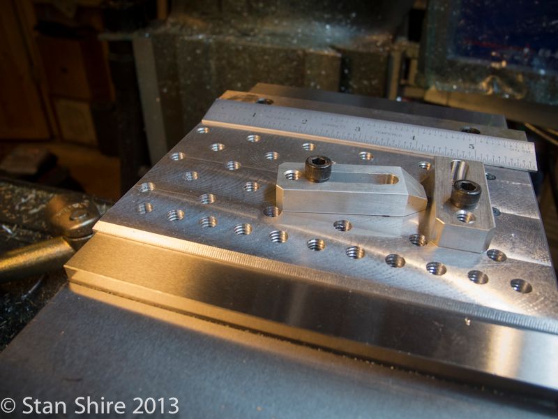
So I could make this


So I could hold small parts. And speaking of small parts and overkill.


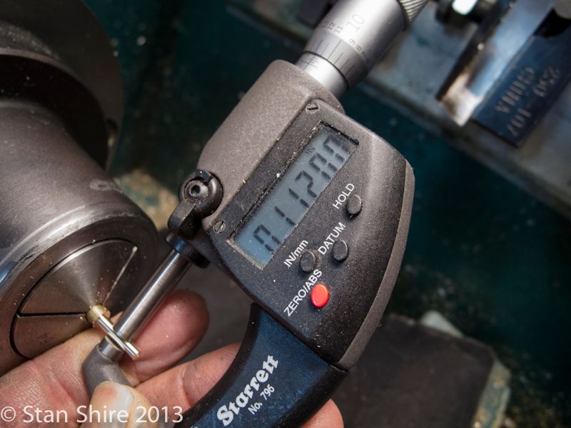
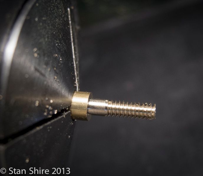
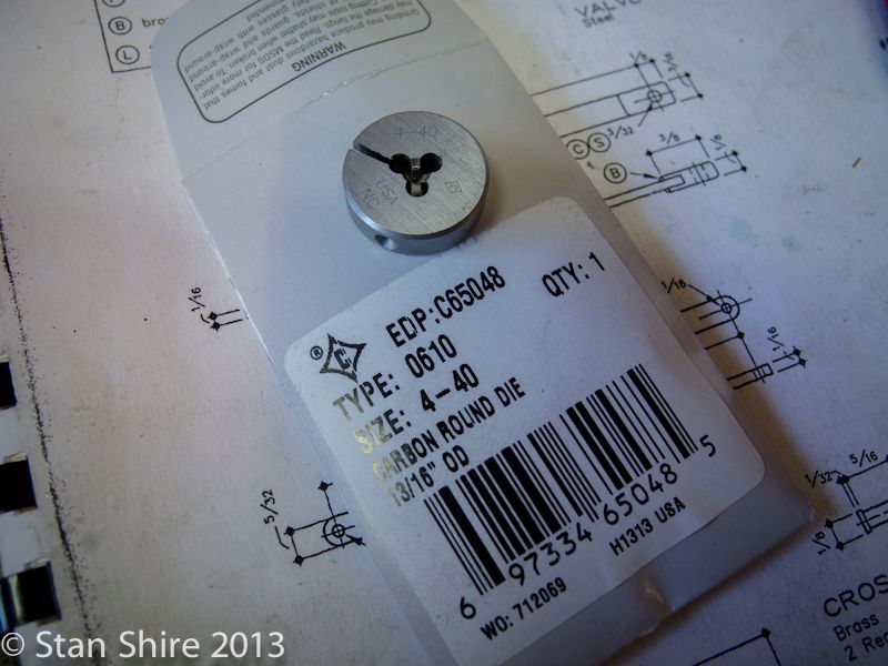
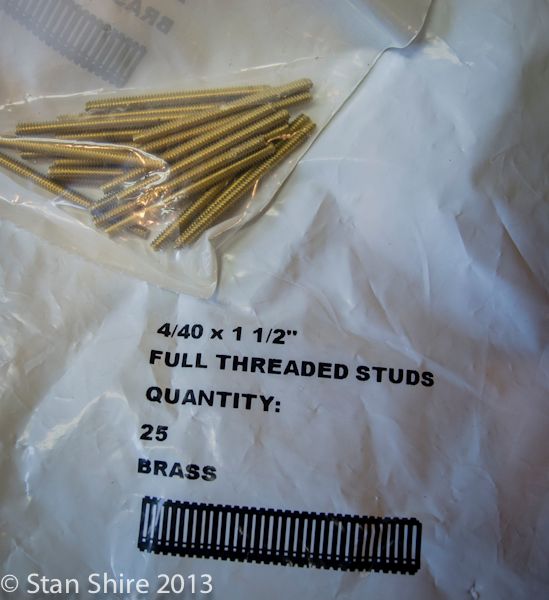
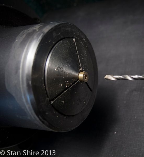
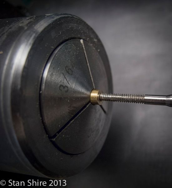
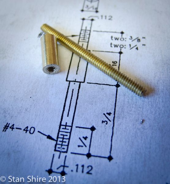
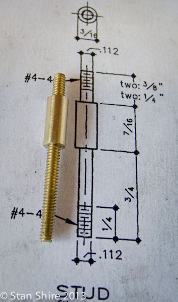
Onto the studs. The new, Made in USA, 4-40 die arrived from McMaster. I turned the end down to the 4-40 major diameter of .112


I managed this.


But only after wedging the die open to turn the screw in and reducing the diameter to .101.


I couldn’t get a factory-made 4-40 SHCS to even start in the die. It’s going back to McMaster. On to Plan B.


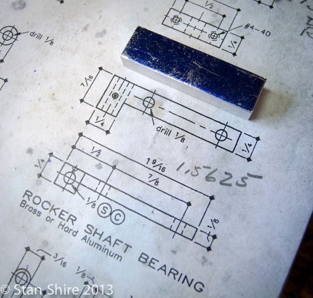
With those done, it was on to the rocker shaft bearing.

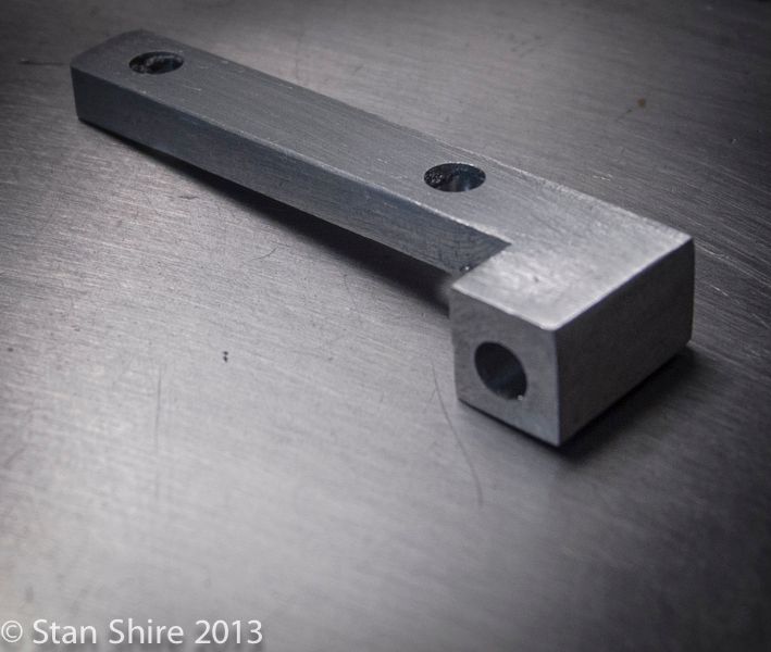
The stock, squared up and milled to size.


Just some milling and drilling.


Another part is checked off.


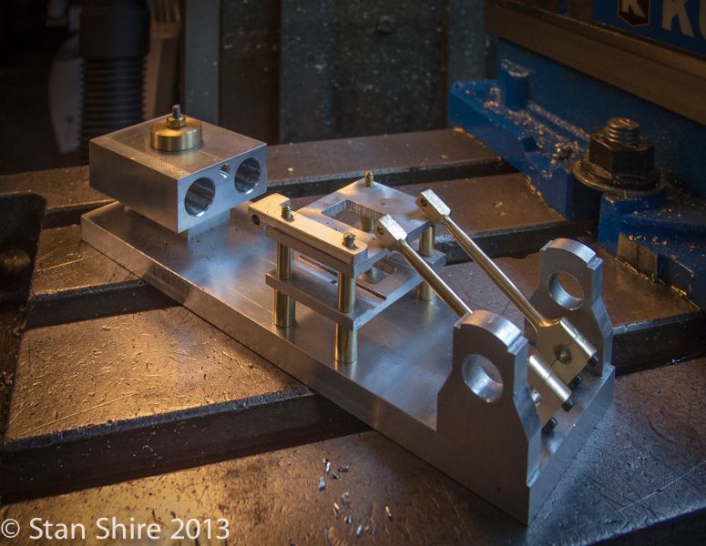
This is the progress so far. Doesn’t seem like much, but with the holidays and the DRO issues (another thread) I’m back on track. Richie (my UPS guy) picked up the DRO scale a few minutes ago and it’s on the way to the hospital in California.

 
Double-Cross
Elmer’s #34 - Cross Twin Engine
Part 7


Today was Rocker Crank Arm day. (only celebrated during odd-numbered years in which February has an even number of days.)


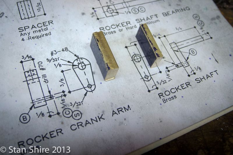
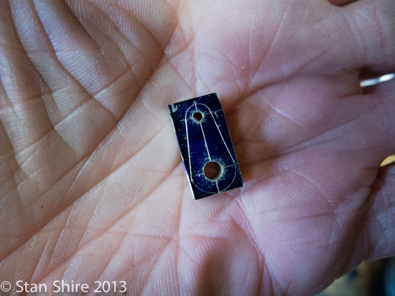
I’ve milled this part and tomorrow’s rocker shaft to size, then did some marking out and drilled the .125 and .0625 holes.


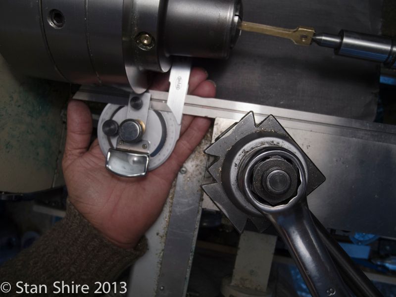
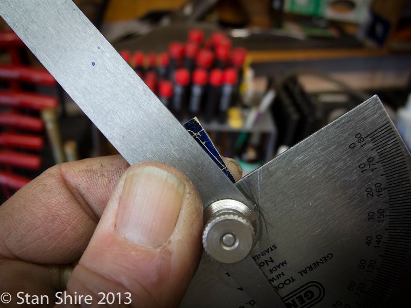
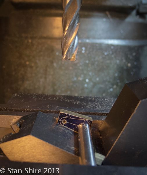
After precisely measuring the angle (“That looks sort of close”)…..


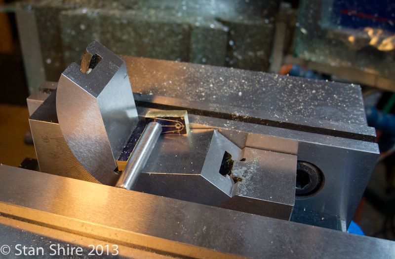
Mounted in the angle fixture for milling.


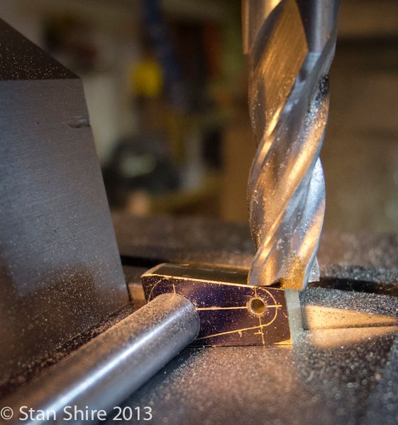
That split the line. As Keith Fenner says, “I’m happy with that.”


Recalculated the angle, for the other side and reset the vise.


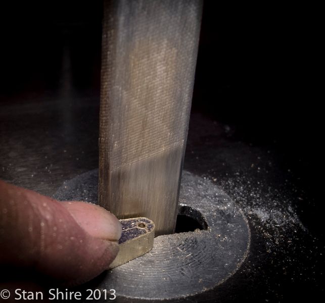
I was going to set up the rotary table and turn the locating studs to round the ends, but that would be about an hour I’d never see again. Actual time at Oliver was 5 minutes.


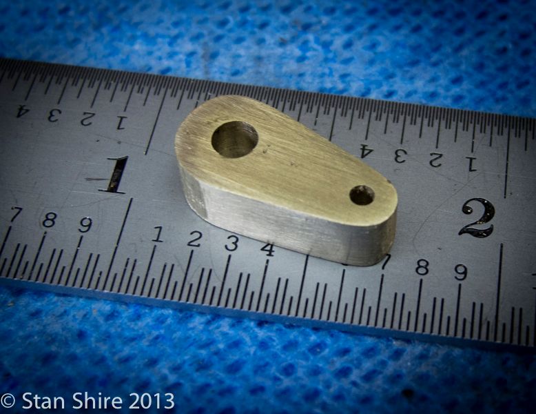
Another part gets added to the “done” pile.


Thanks for stopping by.
 
Nice job looks great! I see you are buying brass studs I did much the same on Ebay for stainless steel 4-40 5/8 set screws to use as studs on my 9 cyl and 18 cyl Radial from Lee's plans. To me it's a lot easier than trying to thread long studs or tie bars. Keep up the good work I'll keep watching to get some pointers.
Thanks
Todd
 

Latest posts

Back
Top