DIY Tesla Impulse Turbine

Home Model Engine Machinist Forum

Help Support Home Model Engine Machinist Forum:

This site may earn a commission from merchant affiliate links, including eBay, Amazon, and others.
Divergent Nozzle; old on the bottom and newly drilled out holes on top.

Divergent Nozzle Holes sml.jpg
 
Have you considered a Tesla Turbine without the "support/impact" bar (or whatever you call it?).
I reckon my Tesla turbine needs 87,000rpm to reach "sonic" perimeter speed. (Using speed of sound in air at atmospheric pressure). I understand the full "tesla" effect does not happen until the discs approach that speed.
Or maybe the "Impact" bar without the Tesla turbine? (like a Pelton wheel?). The circumference will then only max at ~0.5 x sonic speed or ~44,000rpm for a 3 in rotor.
I still believe they are such conflicting technologies that you should have one or the other as with both you get the worst of both ideas?
The De Laval turbine is described here:
https://archive.nptel.ac.in/content/storage2/courses/112104117/chapter_6/6_6.html
With an extract here to give you a taste of the design (for those that don't know- like me!).
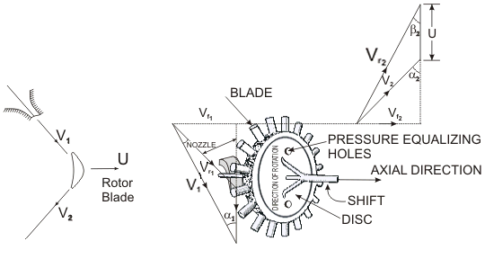
  • The Single-Stage Impulse Turbine
    The single-stage impulse turbine is also called the de Laval turbine after its inventor. The turbine consists of a single rotor to which impulse blades are attached. The steam is fed through one or several convergent-divergent nozzles which do not extend completely around the circumference of the rotor, so that only part of the blades is impinged upon by the steam at any one time. The nozzles also allow governing of the turbine by shutting off one or more them.
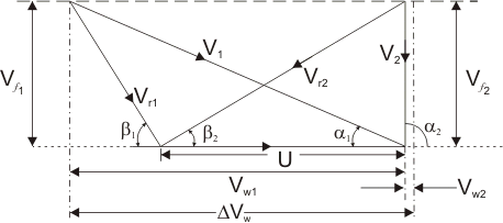
    The velocity diagram for a single-stage impulse has been shown in Fig. 22.1. Figure 22.2 shows the velocity diagram indicating the flow through the turbine blades.

    1d.gif

    Figure 22.1 Schematic diagram of an Impulse Trubine​
6_6_clip_image002.gif
and
6_6_clip_image004.gif
= Inlet and outlet absolute velocity

6_6_clip_image006.gif
and
6_6_clip_image008.gif
= Inlet and outlet relative velocity (Velocity relative to the rotor blades.)

U = mean blade speed

6_6_clip_image002_0000.gif
= nozzle angle,
6_6_clip_image004_0000.gif
= absolute fluid angle at outlet

It is to be mentioned that all angles are with respect to the tangential velocity ( in the direction of U )

2b.gif
Figure 22.2 Velocity diagram of an Impulse Turbine


6_6_clip_image006_0001.gif
and
6_6_clip_image008_0001.gif
= Inlet and outlet blade angles
6_6_clip_image002_0007.gif
and
6_6_clip_image002_0008.gif
= Tangential or whirl component of absolute velocity at inlet and outlet

6_6_clip_image014_0000.gif
and
6_6_clip_image016_0000.gif
= Axial component of velocity at inlet and outlet

Tangential force on a blade,

6_6_clip_image002_0010.gif
(22.1)
(mass flow rate X change in velocity in tangential direction)

or,

6_6_clip_image002_0011.gif
(22.2)


Power developed =
6_6_clip_image002_0012.gif
(22.3)
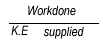
Blade efficiency or Diagram efficiency or Utilization factor is given by

6_6_clip_image002_0013.gif
6_6_clip_image002_0006.gif
or,

6_6_clip_image002_0004.gif
(22.4)


It gets into Maths that depart from my understanding after this...
 
I've been reading that the efficiency of a De Laval turbine is roughly 85 to 90%; of course, that's design efficiency which is seldom, if ever, achieved. Still, being able to extract even 80% of the energy contained in steam in only a single turbine stage is quite an achievement.
Indeed, and it runs at a peripheral velocity equal to about 1/2 the velocity of the steam being discharged from the nozzles, whereas a Tesla turbine needs to have a peripheral velocity almost equal to the velocity of the steam. So the De Laval needs less gear reduction and is subject to far less centrifugal stress.

I think that both designs could be made to run at low speed with reasonable efficiency, but to do this the pressure drop across the nozzles must be low (to keep the steam velocity matched to the turbine wheel) and you would thus need many stages to fully expand your steam. Little doubt that reaction turbines are a better match to low shaft speeds, but the difficulty of making the guide vanes and blades on our scale is probably prohibitive.
 
Have you considered a Tesla Turbine without the "support/impact" bar (or whatever you call it?).

The photo of all the discs mounted together can be a bit misleading; what may appear as a solid bar, is actually all the tiny flat plate blades lined up. The pic below shows a single disk. (My apologies for the poor image quality.)
Tesla-Impact Disc sml.jpg


In this photo, I flipped a few discs to intentionally alter the "bar" appearance.
Rotor & Housing.jpg


I still believe they are such conflicting technologies that you should have one or the other as with both you get the worst of both ideas?

We'll both have a better idea when I finally push some steam through this thing :)
 
In order to get a better idea of power output from my Tesla-Impulse turbine, I assembled a new adapter which replaces the centrifugal pump, and connects the turbine through a coupler to a smallish 500 Watt spindle motor. The motor is rated for 48 vdc at 12,000 rpm, which I expect the turbine will exceed, probably by a lot,...but I have this motor in my parts box, so this is where I'll start. Now I need to find a few appropriately sized load resistors :)

Turbine & 500W Motor sml.jpg
 
Maybe this is a clue... A 3in dia Tesla Turbine with 100psi air applied easily reached 20,000rpm free running with knackered bearings and before the reflective tape flew off. - So I didn't bother running it faster. On steam it only did a couple or 300rpm as the water (condensate) turned it into a water pump/paddle wheel! I added a tiny drain but needs more "tuning" yet (BIGGER drain!). - AND some half-decent bearings...
Against a 50VDC motor, with 10:1 reduction gearing, it didn't manage more than a couple of hundred rpm using 100psi air, due to gear-drag and magnetic (motor) drag. So you can either have speed, or not, as the torque (pre-Tesla spiral gas flow mode) is not very good. You should assume "no power" from your turbine for the Tesla mode.
On a drawing, how does a 9degree included angle cone from the gas nozzle match the "end blade" of your turbine blades? There is usually a spacing given so one blade is just joining the jet-stream as one is leaving the jet-stream... In my Model Turbine book it shows a 3 1/2inch turbine wheel with 40 blades as one the author developed. For your steam jets the jet axis should be tangential to a circle when it sees the centre of the "blade" perpendicular to the jet. Possibly it could be improved if you gave each "blade" a concave surface facing the jet and convex surface at the back?
And don't forget balancing the turbine to the best of your ability as that really makes a difference to the bearing friction and life.
I guess you know this, but it may help others?
K2
 
In order to get a better idea of power output from my Tesla-Impulse turbine, I assembled a new adapter which replaces the centrifugal pump, and connects the turbine through a coupler to a smallish 500 Watt spindle motor. The motor is rated for 48 vdc at 12,000 rpm, which I expect the turbine will exceed, probably by a lot,...but I have this motor in my parts box, so this is where I'll start. Now I need to find a few appropriately sized load resistors :)

View attachment 156303
That's so professional looking!

Before you pump in steam, might be neat to leave the brass nozzles out and spin up the motor to see how much air the turbine will pump.
 
Maybe this is a clue... A 3in dia Tesla Turbine with 100psi air applied easily reached 20,000rpm free running with knackered bearings and before the reflective tape flew off. - So I didn't bother running it faster. On steam it only did a couple or 300rpm as the water (condensate) turned it into a water pump/paddle wheel! I added a tiny drain but needs more "tuning" yet (BIGGER drain!). - AND some half-decent bearings...
Against a 50VDC motor, with 10:1 reduction gearing, it didn't manage more than a couple of hundred rpm using 100psi air, due to gear-drag and magnetic (motor) drag. So you can either have speed, or not, as the torque (pre-Tesla spiral gas flow mode) is not very good. You should assume "no power" from your turbine for the Tesla mode.
On a drawing, how does a 9degree included angle cone from the gas nozzle match the "end blade" of your turbine blades? There is usually a spacing given so one blade is just joining the jet-stream as one is leaving the jet-stream... In my Model Turbine book it shows a 3 1/2inch turbine wheel with 40 blades as one the author developed. For your steam jets the jet axis should be tangential to a circle when it sees the centre of the "blade" perpendicular to the jet. Possibly it could be improved if you gave each "blade" a concave surface facing the jet and convex surface at the back?
And don't forget balancing the turbine to the best of your ability as that really makes a difference to the bearing friction and life.
I guess you know this, but it may help others?
K2

In place of a drawing, just use this photo; each of the 6 brass nozzle assemblies can be rotated a full 360 degrees; of course, we're only interested in angles that have the nozzles pointed towards the discs. Although this design prevents a perfectly tangent line on the discs from the center of the brass nozzles, the angle does get pretty close to tangential. The steam jets should also "hug" the housing walls due to coanda effect, meaning a perfect tangent line shouldn't be necessary. The brass nozzles are adjustable during operation, as a short section protrudes through the bottom of the housing, (see post#66).

Each jet stream travels only 1.3" before it encounters the next jet stream, which will push the first stream towards the axis. This short 1.3" stream travel is where the impulse blades should be extracting the majority of the steam's energy.
Nozzle Housing Rotors sml.jpg
 
That's so professional looking!

Before you pump in steam, might be neat to leave the brass nozzles out and spin up the motor to see how much air the turbine will pump.
The turbine does pump a tiny bit of air even through the nozzles, when turned by the spindle motor.

But I'm not sure removing the nozzles will work. The top of each brass nozzle assembly is sealed with an O-ring, so if I remove the nozzles, the seal between the channels in the housing will be lost,...still might be worth a try.
It would make a neat data point lol.


Can't wait to see it on full steam.
 
As the Tesla pressure profile in a pump is max pressure exerted "outwards" = non-directionally but just away from the discs (I think?) - then you should simply be able to put a pressure gauge on the "steam supply line" instead of steam, and spin the motor to the best speed it can achieve and record the Pressure attained. (Not flow). - I think?
Putting a "DUMMY" pipe instead of jets at one point and you should be able to extract the compressed air and then do further pressure & flow studies if you wish?
Part of the "beauty" of Tesla's turbine as a rotational power generator is that is works in reverse as a pump. Pumps are the commonest use of his turbine - or so I have read?
https://www.gyroscope.com/d.asp?product=TESLATURBINE
https://teslauniverse.com/nikola-tesla/articles/tesla-steam-turbine
https://www.quora.com/What-are-the-advantages-of-using-the-Tesla-turbine-pump
https://www.researchgate.net/public...of_Tesla_Turbine_using_Open_Flow_Water_Source

Food for thought?
K2
 
I might be wrong, but I think (just like in the case of aircraft wing), a continuous linear nozzle with the apropriate profile, would give a little better results than a series of circular ones, and with a bit of chance would be easier to machine. I would say, replacing multiple nozzles by a single one generates a single wave front, avoiding turbulence interferences, hence a slight gain.
 
I might be wrong, but I think (just like in the case of aircraft wing), a continuous linear nozzle with the apropriate profile, would give a little better results than a series of circular ones, and with a bit of chance would be easier to machine. I would say, replacing multiple nozzles by a single one generates a single wave front, avoiding turbulence interferences, hence a slight gain.

Slits instead of individual holes for the nozzle have been used in some designs, and quite likely produce a more useful steam flow shape,...but for this first prototype, drilled holes were much easier to machine. A long slit of the same width as the diameter of the current holes would result in a massive increase in nozzle exit area, resulting in a much greater volume of steam flow. Increased steam flow from the nozzles should increase power from the disks, but it may also result in too much steam trying to flow out of the central exhaust holes near the axial, resulting in choked-flow and reduced power; at some mass flow, this will happen,...but I don't know when.

One big advantage of the overall design of the turbine I'm using is that nozzles can be easily removed and replaced, allowing for different nozzle designs to be tested.
 
I really don't know aerodynamics. But my guess is that a small diverging nozzle to send a gas jet to be the width of the gap between plates could be very efficient? But a continuous slot generated air-knife could have issues with gases hitting the edges of the discs then needing to fiddle sideways to get into the slots to proceed through the turbine? May need the discs sharpening to knife edges rather than flat facing the gas stream?
But I follow your notion.
The knife slot for jet stream generation could be quite easy to make from 2 halves, machined and re-joined.
For the discs as shown:
1716359195879.png
I reckon a slot will really work well on the "teeth" as an Impulse turbine. - The gaps are simply an expansion chamber than as the remaining steam energy heads for the exhaust hole like a Tesla turbine in "starting" mode. One hopes the steam stream is revolving in the correct direction or it will be counterproductive!
K2
 
K2, you're also right! But.
Aerodynamics is also part of gas dynamics. There is no either one or the other.
Second, jets coming from nozzles are divergent so they soon reach a larger extent than the spacing of disks. Of course, the core remains smaller and maintains a lot of original kinetic energy, but at the edge the flow is much turbulent and in addition 2 adiacent jets interfere with this turbulent zone, leading to losses and reduced transfer to the disks which are placed exactly in this border area. Turbulent flow prevents gas jet "sticking" to disks. Of course, the net impact should be fractions of output.
Also some fractions mean interference between air-knife and disk edges. So, until proven, we have to bet.
And you are right about potential 2 halves machining and maybe an adjustable opening nozzle (think of dove-tails).
 
Last edited:
Drag wise - at subsonic velocities, domes or in this case, rounded edges generate less resistance then sharp edges or points. A flat nose cone, subsonic, has only slightly more drag then a sharp point.

Think wad cutter ammo, or the shape of a jumbo jet nose.

Or a velocity stack.
 

Latest posts

Back
Top