Cx701 lathe report

Home Model Engine Machinist Forum

Help Support Home Model Engine Machinist Forum:

This site may earn a commission from merchant affiliate links, including eBay, Amazon, and others.
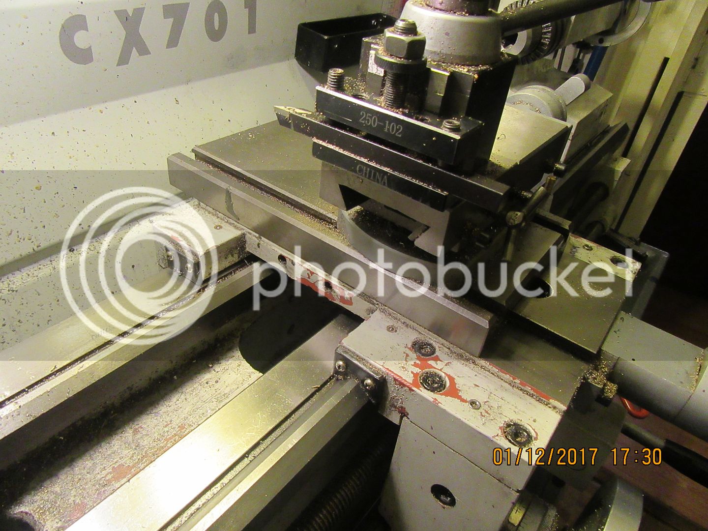
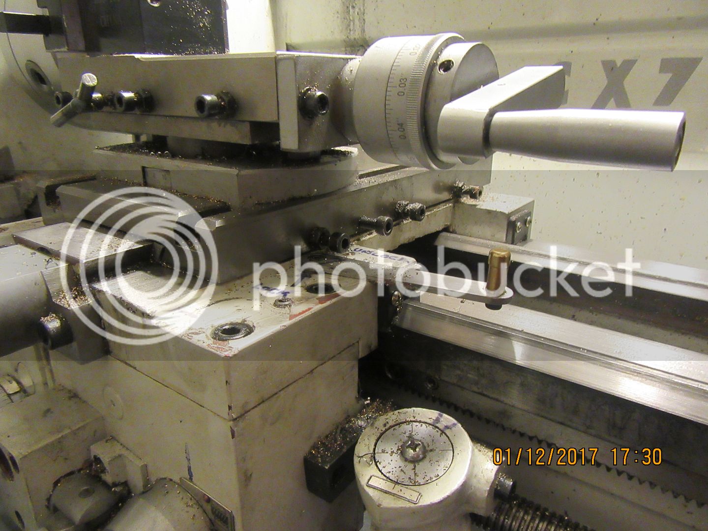
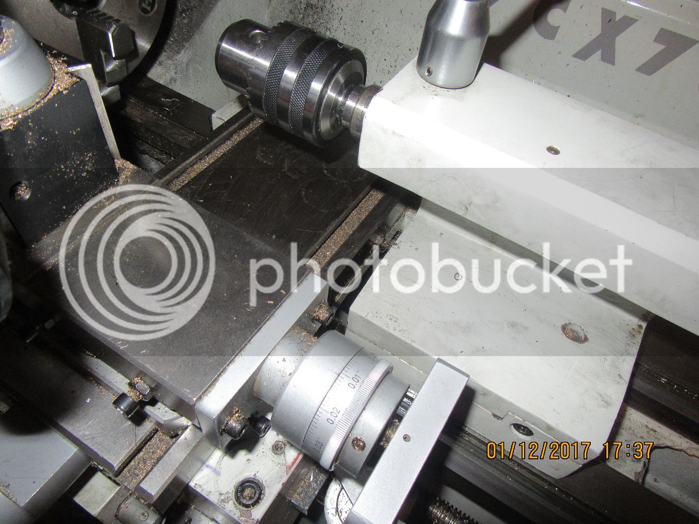
Brian, I've had this installed for 4-5 years so I'm confident its going to stay put. Attaching pics to give you some perspective. We don't have the same lathe or DRO encoders but hopefully you can interpolate. I guess there's always that risk you could damage encoder when exposed to chuck business side. I don't run flood coolant but I do occasional dirty stuff (cast iron & toolpost grinding). Generally I'm pretty anal about cleanliness & bed protection though. It might be worth soliciting a more few opinions specific to your encoder type (ie. maybe being less forgiving to swarf & debris). Mine are Newall which are sealed CF rods with steel balls inside as opposed to glass scales or other systems out there. That might be a factor. I mounted a simple aluminum L channel protector so its well covered. I peek in there once in a while & vacuum but it stays essentially clean.

Your tailstock comment is a valid one me thinks. My cross slide/tailstock casting shape might be just a bit more tolerant, but I could see that being an issue especially if its possible for tailstock to physically contact encoder by too far left. Basically I dry assembled components with double stick tape or wood mockups & came to the conclusion this was worth a shot. Worst case scenario I had 2 small redundant holes in my cross slide. I could have drilled the lower casting member with a hand drill but I wasn't cherishing the thought. The bigger headache was relocating my cross slide lock screw because it has to bear against the gib strip which is on tailstock side.

BTW, I think free-hand drilling & tapping like the video might be asking for trouble. I made some simple bushing type drill guides just temporarily tacked with double stick tape or epoxy.

IMG_5719_edited-1.jpg


IMG_5718_edited-1.jpg


IMG_5717_edited-1.jpg


IMG_5716_edited-1.jpg


IMG_5715_edited-1.jpg


IMG_5714_edited-1.jpg
 
If I mounted encoder on right side of cross slide this is what I was looking at. Red=encoder, Orange=bracket mount, 1=cross slide lock screw likely interference (contacts gib strip on this side) 2=carriage lock screw likely interference.

2017-01-11_22-51-13.jpg
 
Peter,

I had the same problem with my lathe, the glass scale covered up the gib tightening screw (tapered gibs so no problem with adjusting those).

This is how I got around the problem when I looked at fitting the scale on the forwards face and realised it was very liable to be damage by something swinging around in the chuck.

It took hardly any time at all.

http://chestermachinetools.forumchitchat.com/post/locking-up-my-cross-slide-7284193?pid=1286083315

I also fitted the one on my top slide the opposite to yours, mine is on the outside, to stop fouling by the tailstock, but I still have to do the same to that.

Spindle10.jpg


John
 
John, it was your post that inspired me to similarly retrofit my lock screws with the tapered plug & ball bearing assembly. First on lathe, then same fix on the mill XY travels. Nothing like a DRO to illustrate unwanted movement that one can impart to tool setting just trying to lock it down.

Anyway, I mulled over moving the lock screw to chuck side too. It came down to a few soft issues I was (personally) less comfortable with, maybe more out of naivety at the time:

- I've been in the habit of locking carriage with my right hand on pretty much every lateral pass, even if only lightly on roughing passes. The thought of changing my habits & sticking my left hand in under the powered/moving chuck every pass, especially on short stock pieces with less room, just seemed like one of those 'sooner or later' type safety things.

- I wasn't clear if [left side scenario] pushing the set screw wedge against the dovetail was going to be as effective holding lock as [stock right side scenario] pushing the set screw against the gib strip which then maybe imparts pressure along a broader dovetail contact area? I suspect now probably no difference.

I think this is one of those choose what's best for you solutions, but at least now Brain has some more points to ponder.

Just curious, on big boy industrial lathes, do they lock the cross slide in this same set screw manner?
 
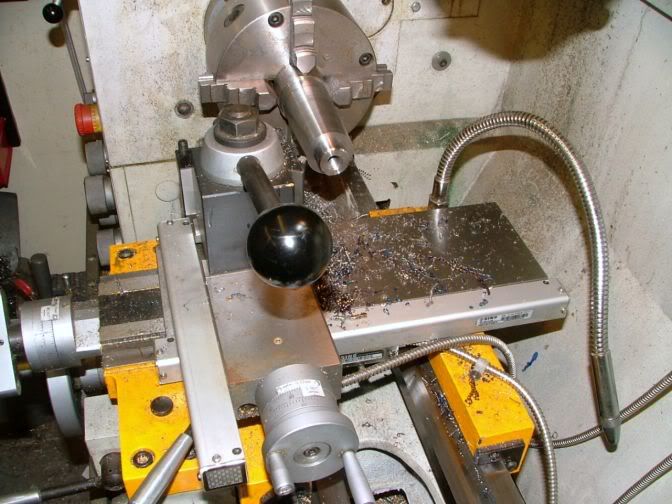
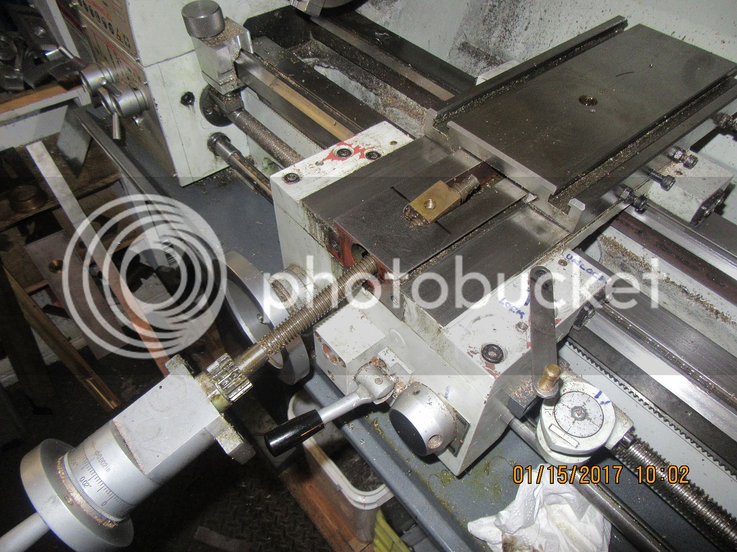
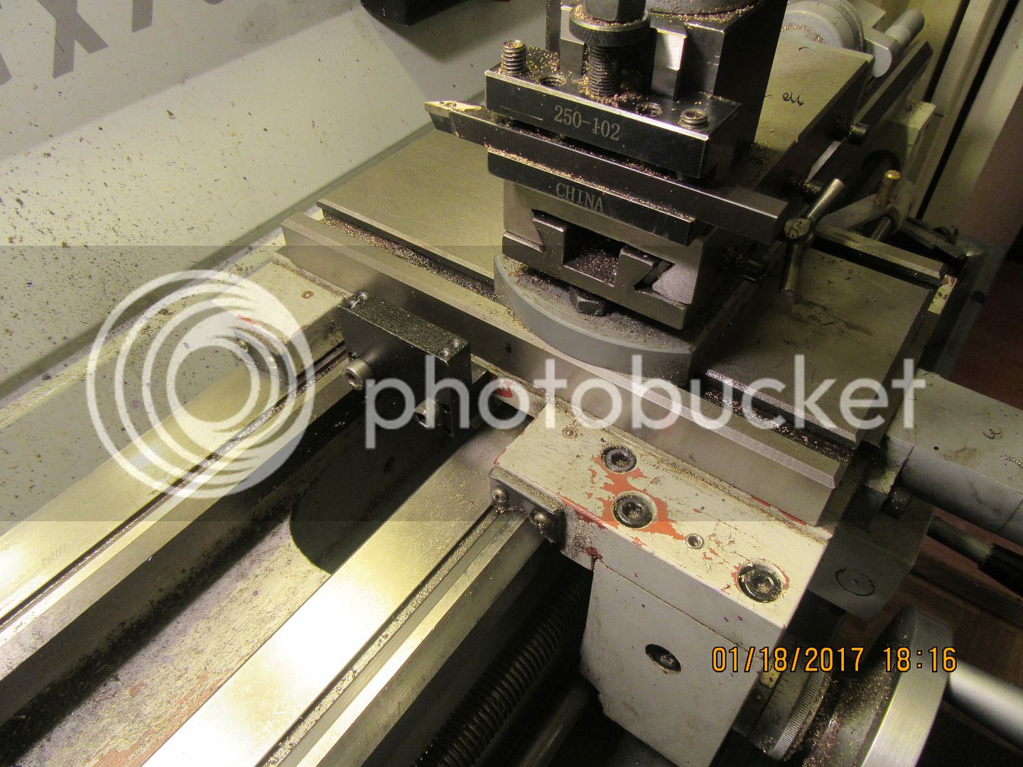
The first picture here, shows the side of my cross-slide which is closest to the chuck. It is perfectly "clear" with the exception of two tapped holes, which are meant for the travelling steady-rest, which I never use. The second picture shows the side facing my tailstock, and it is very cluttered up with gib adjusting bolts and a cross-slide lock bolt. Although Dro-Pro strongly suggests mounting the cross-slide DRO and read head to the tailstock side of the cross-slide in their "how to mount scales" video, it would be pretty complicated for me to do so. Perertha has said that on his lathe which is similar to mine, he mounted the DRO to the side facing the chuck, and utilized the tapped holes as mounting holes for the read head bracket. This makes a great deal of sense to me. I don't use flood coolant on my lathe, just squirt on cutting oil or WD40 for turning aluminum. the DRO has a protective angle guard that covers it and the read-head.

 
Another good reason for mounting my DRO to the side of the cross-slide closest to the chuck is shown here, although it is somewhat hard to see. When I want to get my tailstock as close as possible to the main lathe chuck for drilling a hole in something without having the tailstock ram extended out a mile, the tailstock will nestle right in tight to the gib lock screw. If I hung the DRO off that side, I wouldn't be able to do that anymore.
 
There are so many ways to fit things to your machinery, all you can do is give it a good dose of looking at, even more thought, then go for it. Hopefully it will all work out for you in the long run.

I fitted mine a few years ago, and as luck would have it, most of it worked out perfectly OK. The only failure was my first fitting of the tailstock DRO, which with a combination of the wrong material used for the sliding rail and lack of protection against swarf caused a major rethink, but that has now all been solved.

Even people with exactly the same machines can end up doing things differently. All we can do is give maybe a bit of logical advice in the hope that it helps.


John
 
Some slow and very cautious disassembly shows that yes, the topslide can be easily removed, in order to drill and tap holes in the side of it to mount the magnetic DRO scale on. I can set it up in my milling vice for the drilling and tapping operation, which makes me feel much better than trying to drill and tap it in place. I am always very cautious about disassembling something like this, in case you disassemble something and hear that horrible "clunk-rattle" sound of something coming apart and falling down into the guts of things, making it necessary to disassemble the entire lathe to retrieve the part and re-assemble things. I have pretty well determined that I am going to mount my scale on the chuck side of the cross-slide because of the gib screws and lock bolt being in the way of mounting the scale on the tailstock side. I have researched this extensively, and I see that it is not uncommon to mount the scale on the chuck side, as many lathes have the gib screws and lock screws on the tailstock side, same as mine. As long as a good protection guard is installed over the scale, it will be fine. I just have to remember that if I work in close to the chuck, to check for jaw clearance from the guard.
 
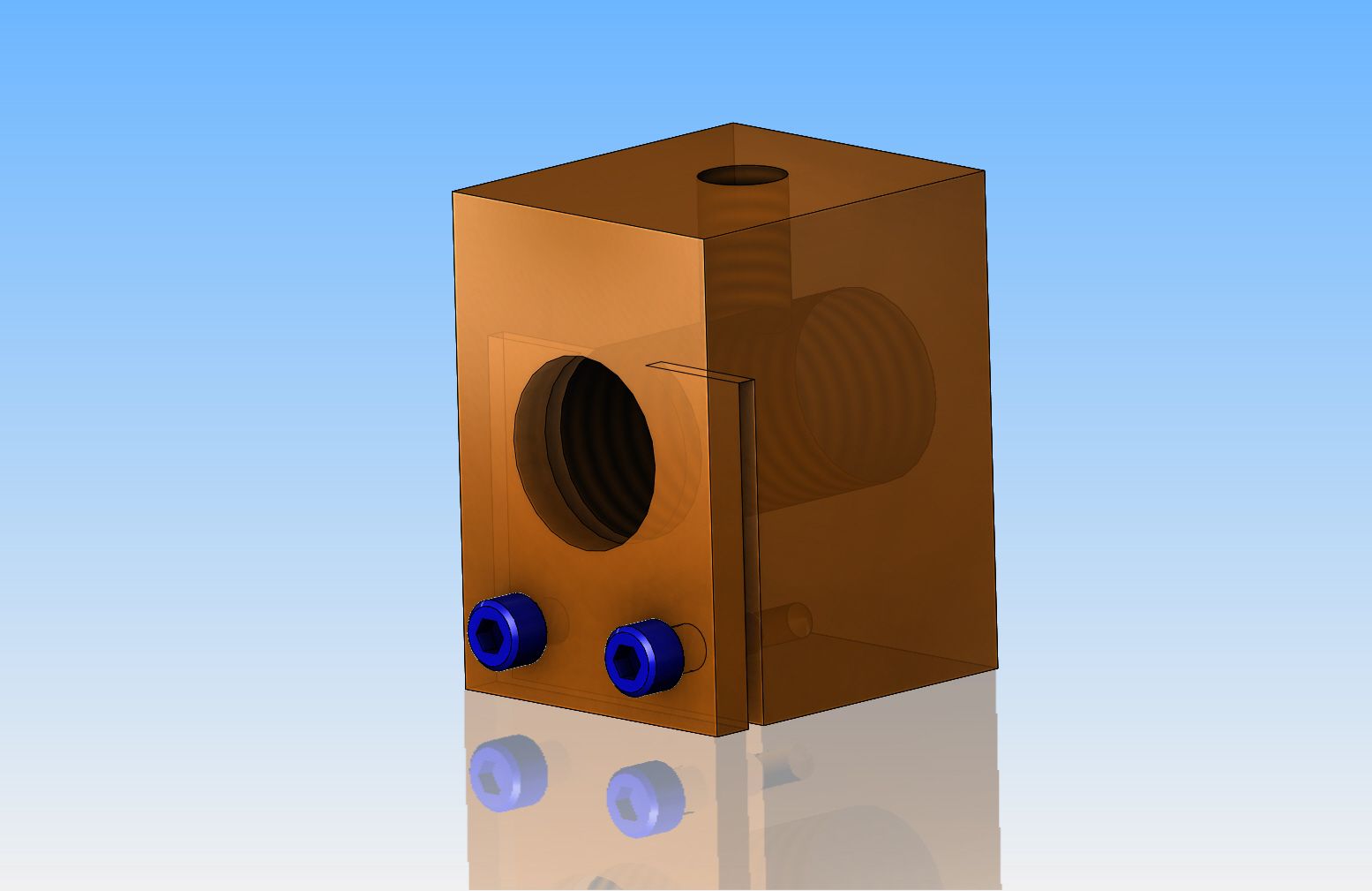
As a point of interest---That brass square nut that the cross-slide lead-screw goes thru has a nifty little adjustment to adjust backlash. You don't see it in the picture, but here is a 3D model of the nut. It has a split part way thru from the bottom, and two small socket head capscrews that when tightened squeeze the slot shut a little bit and tighten up the nut on the leadscrew, thus getting rid of any backlash. This same method could be use on pretty well any nut which is moved by a lead screw.
 
Hi Brian,

I have the same cross slide assembly as yours and have often wondered whether the slide could be put on facing the other way thus having the gib screws on the chuck side along with the gib strip. Do you think that could be possible?
This way would allow the attachment of the DRO scale on the tailstock side but I have not dis assembled anything yet to check this out. Is the screw nut in the centre to allow for a simple reversal.
The cross slide base looks symetrical from your pictures but I have not researched this at all.

Cheers
Steve
 
Makila--That is a very clever idea, and at first glance, it looks like it would be possible.--But--The counterbored hole in the center of the cross-slide which attaches the cross-slide to the brass travelling nut is not centered. Probably if a new counterbored hole was drilled, the cross-slide could be reversed. Only problem then remaining is that the scale mounted closest to the tailstock would then cover up the carriage lock bolt (which I have a handle attached to in the picture).
 
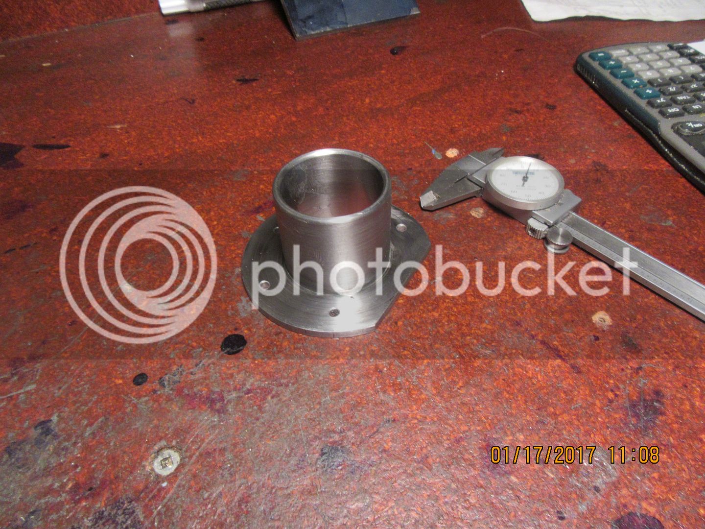
And so it begins. My dro set is in transit somewhere between Canada customs and my house, so I've been notified. I have watched two dozen videos of DRO installations on many different kinds of lathes to educate myself. A common theme on the installations I like has the armored connector cables from the two read heads passing thru a bushing in the pan underneath the lathe and going up behind the splash guard to the digital readout. This bushing has a flange and a gasket, and is high enough to keep any kind of coolant from dripping thru the hole in the pan and onto the floor. As near as I am able to tell, this bushing is not supplied with the kit I bought from Dro-Pros. No problem!!--a bit of rummaging around in my scrap bin yielded a piece of steel pipe approximately 1.4" inside diameter, with a 1/8" wall, and a 3" diameter piece of 3/16" plate. A bit of work with the mig welder on the side that doesn't show, and a bit of clean-up time in the lathe yields a nice flanged bushing to route my cables thru. Even if a bushing does show up with the kit, at least this has amused me for a couple of hours. The flange is cropped on one side so it can snuggle up tight to the backsplash on the back of the lathe.
 
I am looking to fit a 3 axis DRO to my mill.After the chinese new year
of course,any advise would be helpful Brian.Will Try a separate thread rather than hijack yours Regards Barry
 
Brian I hope your cables glide through that hole ok. If they are anything like mine, they have a tendency to kind of get hung up on the hole lip depending on the carriage position. Not a good thing if it snags & you are power feeding. Must be a function of my raised spiral metal wind & their own weight etc.. Hopefully yours are smoother. I mimicked it with a hole in a plate clamped to my chip tray as I'm having to figure out a backsplash. Perhaps it wants something smoothened... like a metal or nylon Tim Hortons donut :) Maybe that's why I see many installations where they just drape the cables over the top ledge of backsplash, but maybe they didn't want to cut a hole or fluid issue as you mentioned.

On another note, I wanted to mention there are some neat follower rest ideas out in web land I've stumbled across that don't rely on the main carriage casting/holes. Maybe not as robust but here is one example to get you thinking (HSM Shop Made Tools - 2013)

2017-01-17_18-47-51.jpg
 
You can see in this shot how my cables go over the top of the splashback.

They were very carefully measured over the whole range of movement of all four cables so that they didn't drag along the bottom onto the drip tray, so not dragging in the swarf produced by the machine. They were then clipped to the top of the splashback with tight fitting nylon P-clips.

Spindle18.jpg


Brian, I can now see why you had to mount your read head along the front rather than the rear, you have a lot of screws sticking out of the back of your cross slide whereas mine doesn't have those as I have tapered gibs on my machine.


John
 
My DRO set-up arrived today, and I have opened the boxes and inspected the components, and everything seems to have survived the shipping okay. After watching all of the installation videos, it seems that my first challenge is going to be that my lathes cross slide body is only 10 5/8" long, with a travel of 6 3/8". According to the instructions on cutting the scale to length, I'm going to end up with the scale being 11 5/8" total length to accommodate that 6 3/8" travel. I will be doing a lot of thinking before I make that cut, so stay tuned.
 
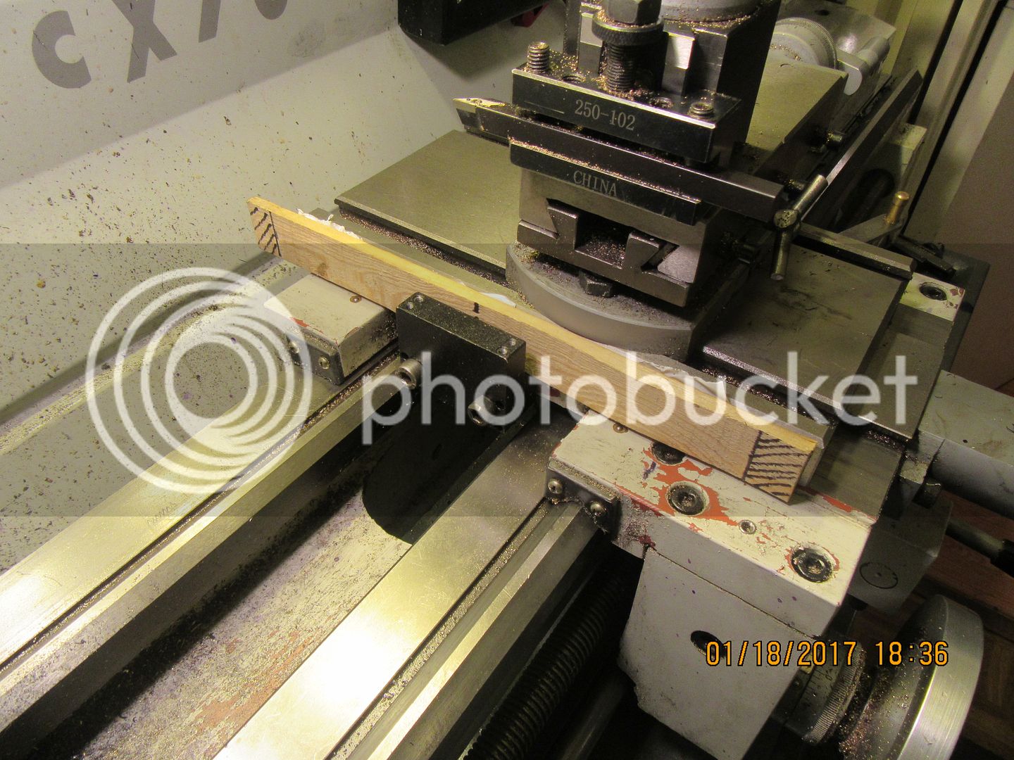
Initial layout to position the cross slide scale and read head. The tapped holes in the saddle are there allready, and I plan on using them to mount the read head bracket. They can not be moved, so I start with them. The center to center on the read head bracket mounting slots is almost but not quite the same as the holes in the saddle, and they are a bit undersize for the M8 socket head capscrews that fit the tapped holes in the saddle. A bit of creative milling moves and enlarges the slots, and Bingo, the bracket is mounted on the tapped bolts in the saddle. The center of the read head bracket must line up with the center of travel on the scale. The piece of wood attached to the side of the cross-slide with double edged tape represents the total length of the scale, and the cross-hatched areas at each end of the wood is the area which must always remain clear of the end of the read head. This layout tells me that if I cut the scale to give an overall length of 11 5/8" and mount it 3/16" in from the end of the cross slide closest to the operator, that when I fully advance or retract the cross slide, the read head isn't going to encroach on the cross hatched area. The end of the scale nearest to the operator can be attached to the cross-slide with a drilled and tapped hole. The far end which is currently hanging out beyond the end of the cross-slide will probably require that I make up a bracket supported from the end of the cross-slide to accept the bolt at the far end. Fortunately, it is easy to remove my cross-slide completely from the lathe and set it up in the milling machine for drilling the required holes. I will then move it to my shop vice to tap the holes as required for mounting the scale. There will be more creative milling required on that read head bracket to position it correctly in respect to the scale.


Latest posts

Back
Top