I know that this was a tiny bit "hokey", but only a tiny bit. I would probably grind my own hss cutter instead of using the carbide, as I can get a much cleaner, better defined cut with hss. Secondly, the "part" would normally be made from steel rather than aluminum if it was for a "real job". However--I was only attempting to go thru all the motions and set-ups required to cut a thread. Everything works, and seems to work very well. It is a bit of a steep learning curve, but there is a lot of information "out there", and the biggest challenge really is learning how to interpret the change gear chart. Thank you to everyone on the forums who helped me. I'm not sure I will ever cut more threads. For what I do, taps and dies work quite sufficiently. I just wanted to be able to say that I have cut a thread on my lathe successfully, and now I have.----Brian
You are using an out of date browser. It may not display this or other websites correctly.
You should upgrade or use an alternative browser.
You should upgrade or use an alternative browser.
Cx701 lathe report
- Thread starter Brian Rupnow
- Start date

Help Support Home Model Engine Machinist Forum:
This site may earn a commission from merchant affiliate
links, including eBay, Amazon, and others.
- Joined
- Dec 12, 2012
- Messages
- 2,220
- Reaction score
- 1,288
Hi Brian,i agree with all you say.I posted a thread on making a collet chuck for the lathe.Sorted the gears out,and turned the chuck by hand to cut
a 40mm x1 thread successfully.Been there and done that as you say
but for 99% of the time taps and dies are sufficient for what we do
I now know/remember how to cut threads on the lathe,its been many years
If needs arise again I know I can do it
a 40mm x1 thread successfully.Been there and done that as you say
but for 99% of the time taps and dies are sufficient for what we do
I now know/remember how to cut threads on the lathe,its been many years
If needs arise again I know I can do it
Hi Baz--It's nice to hear from you. I've always wanted to be able to say "Why yes, I can thread something on my lathe !!". I seriously doubt that it is something I will ever need to do again, but like many things, I wanted to do it at least once correctly, make a bunch of notes and take pictures of it in case I ever need to do it again, and then move on. I like the challenge, and it keeps me engaged with life. I love learning new stuff. --And if my posts help somebody who is struggling to do the same thing, then it makes it even better.---Brian
Congratulations! Looks like the job's a good 'un.
For longer threading jobs, screwcutting will give a more consistent job than using a die, which can wander about the place as it screws on and you end up with a thread that looks like a garden worm.
A good way to do it is to screwcut the longer threads and finish off the last few thou with a die. Quick and easy way to get a straight well finished thread.
- Joined
- Oct 1, 2010
- Messages
- 1,396
- Reaction score
- 426
You've got it. Isn't it satisfying to single-point thread?
I really enjoy all of your posts as you share what you are experiencing (both triumphs and frustrations) as well as what you make.
Keep 'em coming.
--ShopShoe
I really enjoy all of your posts as you share what you are experiencing (both triumphs and frustrations) as well as what you make.
Keep 'em coming.
--ShopShoe
- Joined
- Dec 31, 2010
- Messages
- 813
- Reaction score
- 215
Congrats:
You didn't mention. But I guess you had your compound set over to 29-1/2 degrees? Since you said you used the compound to in-feed?
Most times I don't bother using the compound. It's too much trouble to set to 29-1/2 deg. So I just use the cross slide to in-feed. Of course this means the thread is being cut on both sides of the cutter but if you take light cuts with sufficient lube the thread comes out fine. You also get a true reading of the in-feed rather than some complicated mathematical value based on the 29-1/2 degrees.
Sage

$45.99
Sunnytech Mini Hot Air Stirling Engine Motor Model Educational Toy Kits Electricity HA001
stirlingtechonline

$519.19
$699.00
FoxAlien Masuter Pro CNC Router Machine, Upgraded 3-Axis Engraving All-Metal Milling Machine for Wood Acrylic MDF Nylon Carving Cutting
FoxAlien Official

$40.02
$49.99
Becker CAD 12 3D - professional CAD software for 2D + 3D design and modelling - for 3 PCs - 100% compatible with AutoCAD
momox Shop

$99.99
AHS Outdoor Wood Boiler Yearly Maintenance Kit with Water Treatment - ProTech 300 & Test Kit
Alternative Heating & Supplies

$443.98
TM NEXDYNAMI AT29618 Water Pump Compatible With/Replacement For John Deere 1020 1520 2020 300 301 400 401 440 440A 480 AT29618
VIVID MARKET CORPORATION

$39.99
$49.99
Sunnytech Low Temperature Stirling Engine Motor Steam Heat Education Model Toy Kit For mechanical skills (LT001)
stirlingtechonline
![DreamPlan Home Design and Landscaping Software Free for Windows [PC Download]](https://m.media-amazon.com/images/I/51kvZH2dVLL._SL500_.jpg)
$0.00
DreamPlan Home Design and Landscaping Software Free for Windows [PC Download]
Amazon.com Services LLC

$109.99
AmTech300 - Boiler Treatment Professional Strength (Rust Inhibitor For Outdoor Wood Boilers)
Alternative Heating & Supplies

$154.24 ($1.38 / oz)
Replacement Combustion Chamber Kit, Burnham V8 and V8H, 1-6 Sec, 108136-01, 1129
Plumbing Planet

$54.46
Amana Tool - 46280 CNC 2D & 3D Carving 6.2 Deg Tapered Angle Ball Tip x 1/32 Dia x 1/64
Express Tool Supply
I have watched YouTube video's of it being done both ways. they both seem to work equally well.---Brian
Thanks JasonB, I hadn't noticed the differences in the washers and the manual leaves a lot to be desired in this area. I did learn the paper trick but it was trial and error to find the correct sequence. Thanks for explaining that. I have not tried changing the gears again but will certainly pay attention to the washer thickness.I've replied to Brian elsewher but this may help Sledjunk.
Ringing. If you look very closly at the washers that go between the banjo and the pairs of gears you will see that the are different thicknesses. If you position them wrongly the sides of the gears will rub each other, get them right and they will offset the gears jus enough to clear each other.
Backlash. Make up the gear pairs loosly on teh studs and then starting with teh one on teh leadscrew and next one up cut a thin strip of photocopy paper and feed that into teh gears as you work them together. It will end up consertina shaped. lock the stud with teh paper in place then wind it out. Repeat for the other gears and finally the gear that meshes with te spindle gear as you pivot the banjo back into place.
With luck these two things should give you quiet gears
J
Thanks again.
- Joined
- Dec 31, 2010
- Messages
- 813
- Reaction score
- 215
Brian:
Another small point (no pun intended). You should make yourself a sharp pointed 60deg HSS tool (or see below). A standard carbide turning insert is too round at the point. You (sort of) got away with it for the coarse thread you turned but it wouldn't be any good for anything finer. Being that you turned until an existing nut fit you may have actually cut deeper than necessary to make room for the nut to fit in the rounded bottom threads.
Vardex make a nice "non topping" carbide threading insert. (Available at KBC tools). They work really well on all materials.
Just something to keep in mind if you should ever find yourself turning threads again.
Sage
I am bored, literally, out of my skull!!! What to do?, What to do?---Well, when there is absolutely nothing to amuse me, I invent something. My lathe has a carriage lock on it, which works very fine, thank you. It is the socket head capscrew that the black arrow points at. It is tightened and loosened with an Allen wrench to lock and unlock the carriage.
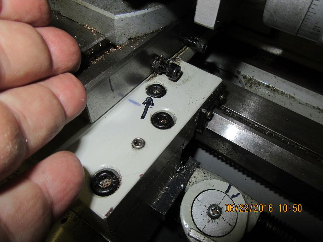

I have checked, and a shorter gib screw won't solve the problem. Even if I replaced the socket head cap on the cross slide with a set screw, there is no room for a locknut to make it hold position without fouling the carriage lock screw.---However---I have checked with my feeler gauges, and I have about 0.188 clearance in there to get a wrench in---just not enough to get a wrench with a stub of Allen wrench attached to it.
Last edited:
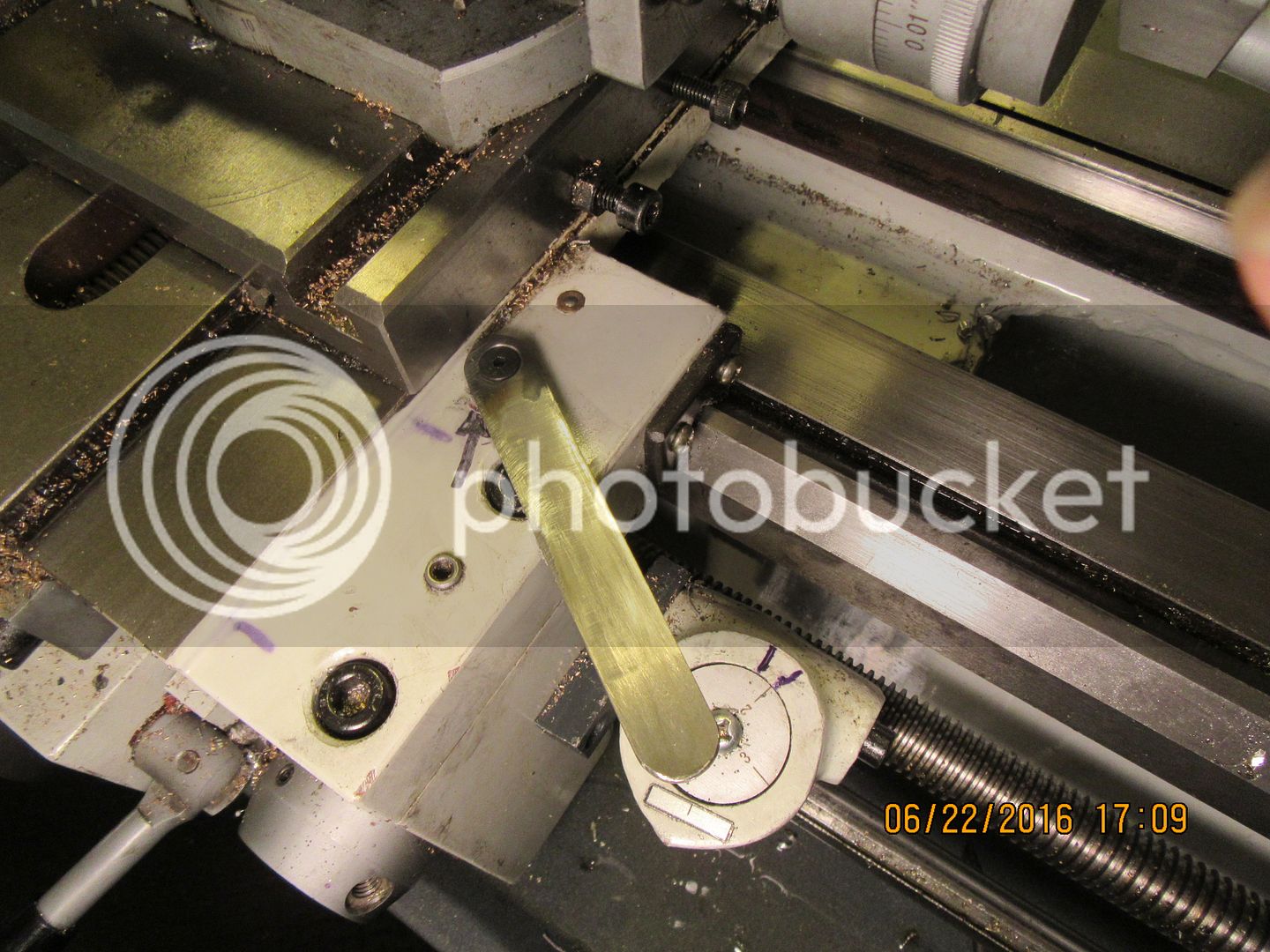
If I was clever enough to machine a piece of thicker material so that it had the required size of Allen head machined right on the face of it, and thread the center of the lock bolt #8-32, and use a #8-32 flat head capscrew to hold the wrench in place, then I could permanently attach the wrench and leave it in place, and the bolt in the side of the cross slide would pass over top of it with no interference. An added benefit would be that I can "clock" the lock screw into a position that would best suit the "stick out" portion of the handle. The hexagon pocket in th ehead of the lock screw gives me 6 positions to choose from. Torque is transferred from the handle to the lockscrew via the machined on "hex" and the flat head capscrew just holds the handle in place.

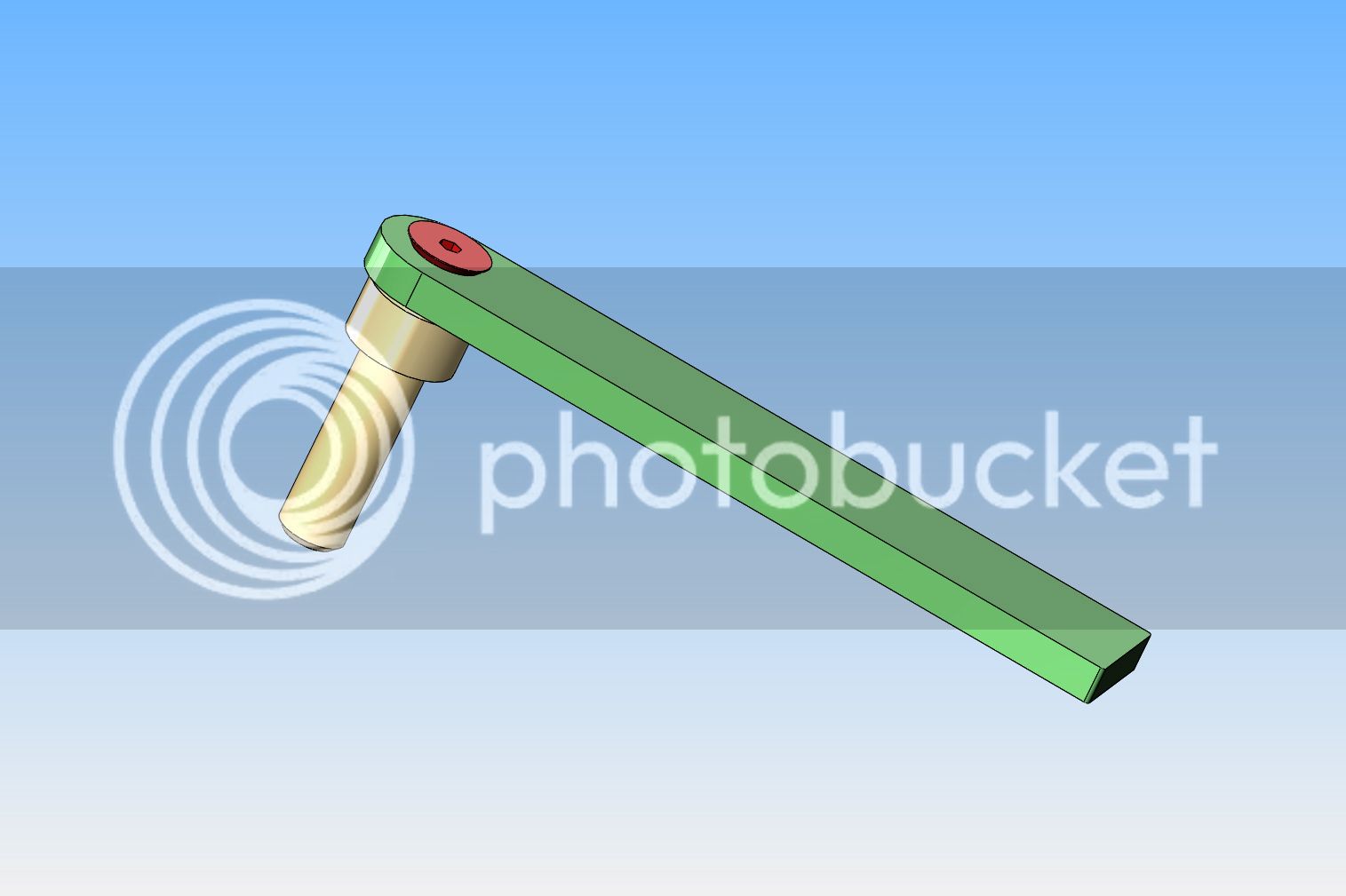


And yes, I could replace the lockbolt with a hex head bolt and then use an open end wrench to tighten/loosen it, but if I do it this way, the handle becomes a permanent part of the carriage, and I don't have to search for a wrench every time I want to lock it.
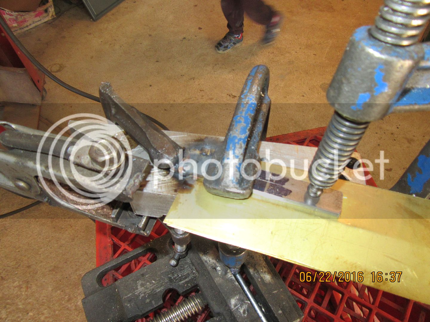
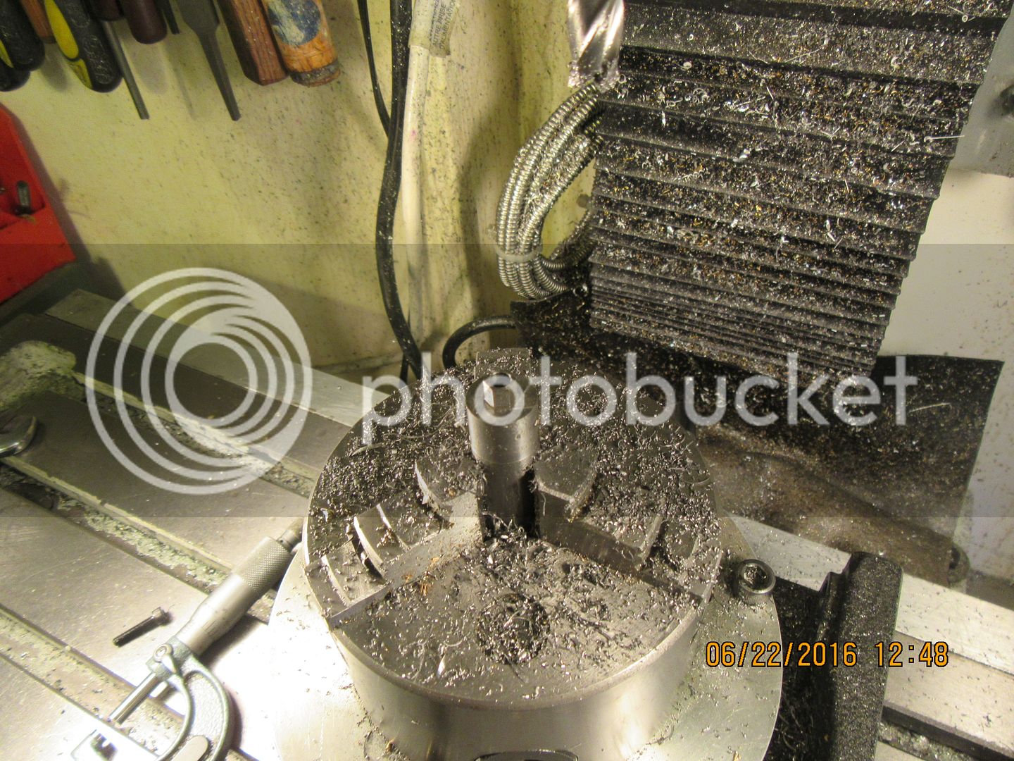
Using the time honoured method of "Use what ya got/ do it whatever way is easiest" I decided to make the wrench in two pieces. (That's why God made mig welders, isn't it?) I set up a piece of 5/8" mild steel round stock in the mill on my rotary table, drilled a clearance hole for a #8 screw, and whittled out a hex shape to fit the carriage lock bolt.

- Joined
- Dec 31, 2010
- Messages
- 813
- Reaction score
- 215
Clever solution..
I don't have the interference problem between the two screws but I also require a wrench to tighten my carriage lock.
I wish I could put a handle on mine like that but the carriage lock screw has to be undone at least a turn or whatever it's tightening below tends to catch and drag when I wind the carriage along.
Nice job.
Sage
Today I ordered a 2 axis magnetic scale DRO set-up from Dro-Pro in California. I will be adding the DRO set-up to this lathe, and documenting the process. Dro-Pro has an excellent set of "how to" videos on doing this, and I watched all four of them yesterday. The only tricky thing I can see is that on my lathe carriage the gib adjusting and lock screws are on the surface that the scale mounts to in the Dro-Pro video. I will have to get creative with some stand-offs I guess.--Stay tuned---
- Joined
- Jun 24, 2010
- Messages
- 2,446
- Reaction score
- 969
I went through similar pros & cons of the cross slide Y-axis. I ended up putting the scale on the left side vs. right side of cross slide.
Positives:
- utilized the 2 existing tapped bolt in carriage casting intended for the travelling steady & saved me drilling those which was otherwise going to be quite awkward
- preserved the right side for (in my case) carriage lock bolt thumbscrew which I always use & would be PITA to relocate so consider that too (my gib adjustment is at the ends of the strip vs. your setscrews)
Negatives:
- scale is adjacent to work so somewhat exposed to swarf etc.(but has not been an issue with protective angle guard installed)
- if I need to use travelling steady, DRO must be removed. I use the steady very rarely if at all, but your mileage may vary
I love my DRO!
Petertha--I find your post very interesting. I very seldom have a use for the travelling steady rest (in fact I have never used it.) The video from Dro-Pro discourages mounting the cross-slide DRO on the chuck side, but on my lathe it would certainly be a lot more convenient. There is also the issue of getting the tailstock chuck in close to drill a short piece held in the headstock chuck. My tailstock will slide in right up to the gib screws on the cross slide, which lets me drill holes without having the tailstock ram cranked out a mile to reach where it has to. If I put the DRO on the same side as the gib screws, I will lose that ability. How long have you had your DRO mounted on the chuck side and have you used the lathe long enough to see any other disadvantages to mounting the DRO there?---Brian
Similar threads
- Replies
- 1
- Views
- 3K
- Replies
- 0
- Views
- 2K


![TurboCAD 2020 Designer [PC Download]](https://m.media-amazon.com/images/I/51UKfAHH1LL._SL500_.jpg)


![[The Haynes GM, Ford, Chrysler Engine Performance Manual: The Haynes Manual for Understanding, Planning and Building High-Performance Engines (Haynes Techbook)] [Author: Haynes, Max] [August, 2008]](https://m.media-amazon.com/images/I/51x6eyiUHhL._SL500_.jpg)


