CX601 Milling Machine

Home Model Engine Machinist Forum

Help Support Home Model Engine Machinist Forum:

This site may earn a commission from merchant affiliate links, including eBay, Amazon, and others.
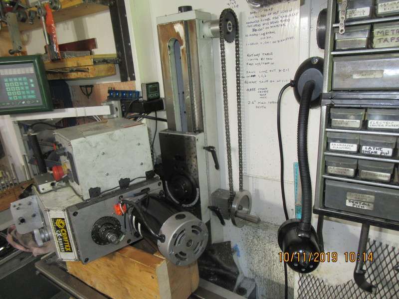
So--Here we are with the head off the mill, setting on a small framework made of 2" x 8" lumber. So far this is pretty easy. There is one major bolt that holds the head to the vertical slider mechanism, and it is accessible from the front side of the machine. There is also one fairly major stud and nut combination which, when loosened allows the head to tilt left or tight to tram the mill head. The entire head pivots on that first major bolt. The entire head which unbolts is extremely heavy. I made sure that the head assembly was only a fraction of an inch above the wood framework before removing the pivot bolt and stud , because I didn't want to have to lift it when it came free. There is an inspection plate on the back side of the head, which I can now access to see whats happening in there. I will swing the entire head and wooden support frame around to give me clearance to remove that inspection panel and look inside.
AqEKcN.jpg
 
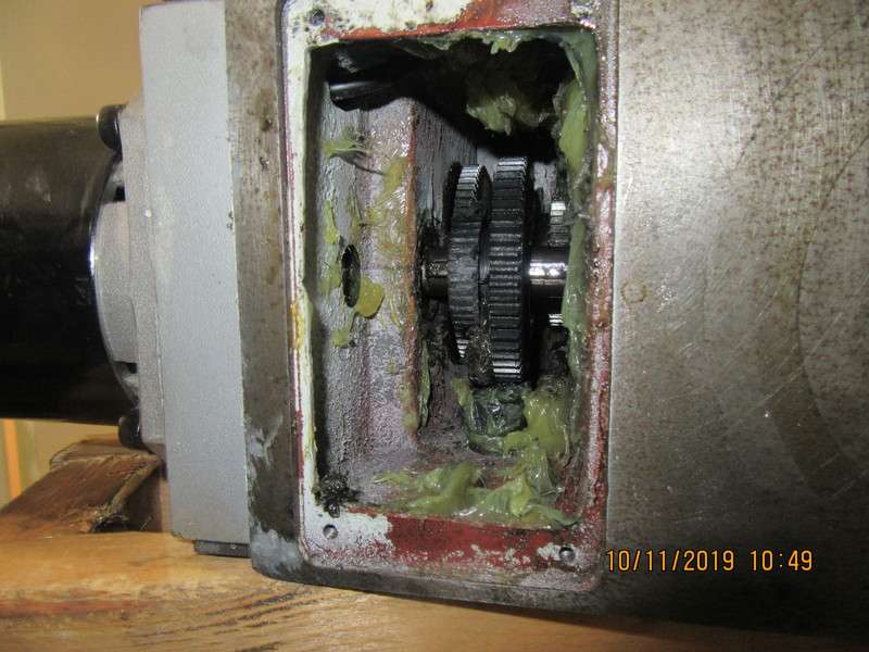
This picture shows the gear selector moved over to "low range" and the gear has moved so the damaged gear meshes with another gear to give "low range". --It hasn't moved all the way into position because of the damaged teeth. I think my next stunt will be to remove the motor and hopefully the damaged gear will come out with the motor. This will give me a chance to check the teeth on the gear which the damaged gear meshes with.
Al5gY6.jpg
 
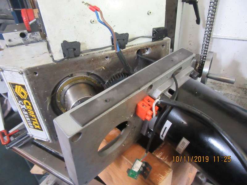
Okay--My bad. The gear in question wasn't on the motor shaft. I pulled off the motor and motor plate, and see that there is a jackshaft between the motor shaft and the mill spindle. The bad gear is on this jackshaft. I have to disconnect some wires, so this is the point where I get out my sketch pad and start drawing pictures with wire colors on them so that after I disconnect them I can remember how it all goes back together. I see a c-clip on the end of the jackshaft, so now I will disconnect the motor and set it aside, still bolted to the motor plate.
dPVP3i.jpg
 
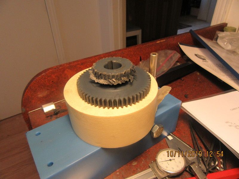
And here is the nasty wee bugger that caused the problem. I did have to phone Busy Bee in Concord to ask how that shaft came out. I thought I seen how it came out, to free up the gear, but I have been bitten on the arse before by "What I thought!" I did have to use my snap ring pliers to remove a couple of bearing retaining snap rings, then drive the shaft out from the bottom with a brass drift punch. I checked out the gears which this one meshed with, ---They are steel and suffered no visible damage. The new gear costs $55 and they have 44 in stock. I will drive to Concord (north Toronto) tomorrow and buy a new gear.
xgojym.jpg
 
Okay, we're good here. I drove down to north Toronto this morning and picked up a new gear. (I get lost every time I drive into the city, and usually get lost when I try to get out again). Brought the new gear home, installed it, greased everything well and the mill is a runner again. No strange squeals, groans, or thumps. I knew before this all happened that my mill had to be trammed, so after I finish this post I will tram it.---Brian
 
Brian,
It happened once, did you get a spare as well? Would save a long drive with getting lost again.
Cheers
Andrew
 
Andrew--If it happens again I may just go looking for a new mill. It's not that long a drive for me--only about 50 miles from here to there.
 
And here is the nasty wee bugger that caused the problem. I did have to phone Busy Bee in Concord to ask how that shaft came out. I thought I seen how it came out, to free up the gear, but I have been bitten on the arse before by "What I thought!" I did have to use my snap ring pliers to remove a couple of bearing retaining snap rings, then drive the shaft out from the bottom with a brass drift punch. I checked out the gears which this one meshed with, ---They are steel and suffered no visible damage. The new gear costs $55 and they have 44 in stock. I will drive to Concord (north Toronto) tomorrow and buy a new gear.
xgojym.jpg
Hi Brian,
My mill is the same as yours. I made a steel replacement for that gear when the plastic gear gave up. It also cured a rhythmic thumping sound that I had from new, which turned out to be caused by the gear not being concentric with the shaft. The plastic gear is used to reduce the noise created by the gears. In my case the noise has reduced.

As far as new mills are concerned, I've been looking at a Sieg SX3.5DZP. All the mods that I've done to mine are standard.
 
A new X axis reading head bracket shaped as shown, will let me get the holes into the dark blue 0.9" off the dark green surface (which is as close as I can get to it with my electric drill without disassembling my milling machine) and still allow me to mount the glass scale almost 1/2" below the top of the milling machine bed For the guard, I think I will forget about a flange along the top and just use a piece of 3/16" thick aluminum angle, supported at the ends only. This lets me keep the top of the angle down 1/16" below the top of the table and leaves 1/4" clearance between the underside of the angle and the top of the glass scale.

Hey Brian,

I have that same mill and am working on some bracketry and such. Are you able to share your 3d model somehow? Maybe as a .step file? Would be greatly appreciated!
Mat
 
Andrew--If it happens again I may just go looking for a new mill. It's not that long a drive for me--only about 50 miles from here to there.
Hi Brian,
I'm in the process of looking for a mill. The toss up has been between the PM25-MV and the CX601. I like the belt drive of the PM and after your and others hassles with the plastic gears in the CX I'm leaning that way. The PM I'm looking at also comes with 3 axis DROs. How long have you had your CX and what is your overall impression. It seems quite a lot heavier than the PM and also has a bigger table. How difficult was it to install the DROs on your machine?
Ron W
 
I have had my machine for 5 or 6 years now, and I am very happy with it. Installing the DRO system makes you scratch your head a bit, but is not terribly difficult. If someone wants my 3d cad files, email me at [email protected] and I will send them to you as .step files.---Brian
 
Hi Brain - thanks for the 3D file, just received my machine yesterday :) . Needed to look up the instructions available with the G0704 machine to turn it on :(. So if others are having problems, need to have the Forward/Reverse switch set to either F/R and the protective guard in place for the machine to start up. I will be installing a CNC upgrade to this machine in the near future ,,, will keep you posted!
 
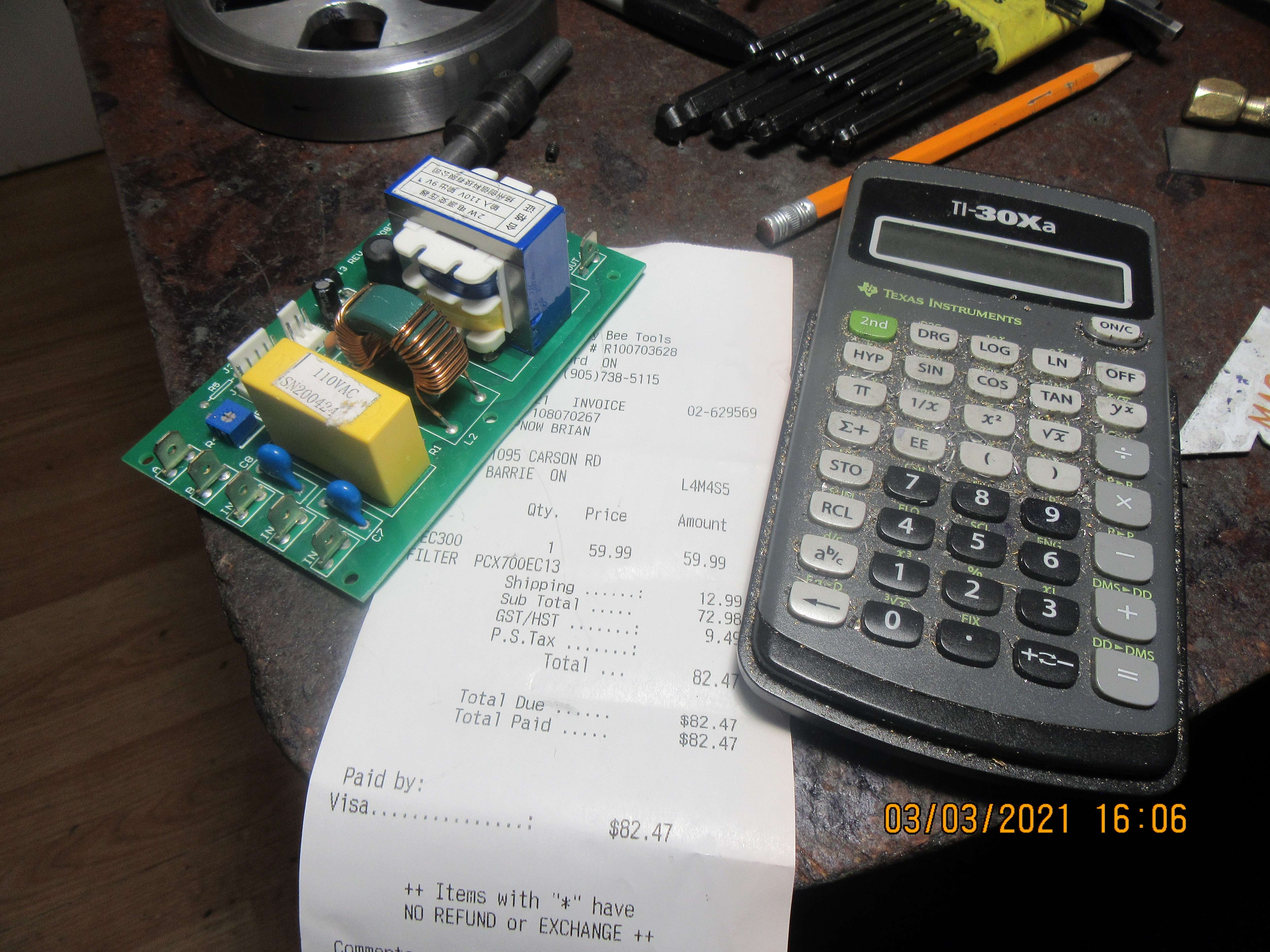
Today I have some new news to share with you. Last week, in the middle of a heavy cut, my mill stopped dead, as if the switch had been shut off. I checked all of the obvious things,--glass fuse, circuit breaker, e-switch and power to the outlet. All seemed to be in order. I called the technician at BusyBee in Toronto, and he said that he is 99% shore that it is an electronics control board in the control box. It is not a big problem to take my mill to Toronto for repair, (It's only 70 miles from where I live) but it is a horrible job to move my mill from my shop out to my garage to load into my truck. The technician knows that I am a fairly handy guy, so he suggested sending the electronics board to me so I could install it on the machine. So---Here is the board and what it cost me. It looks like fairly simple "plug and play". I am going to dive into this, and I will show you my progress, as a lot of people in Canada have this same mill, and it's always nice if somebody puts up pictures of a repair job. In other news---Wife and I just got our first shots of Phizer vaccine for Covid this morning. No drama, no hurt, and no adverse reactions. we go on 14th of April for our second shot.
emM0kQ.jpg
 
Found another post of someone converting his PM-30MV to CNC. The machine is almost an exact replica of the CX601. Anyway's here's the STEP file if people find it useful. Send me a message if you want it.
In the meantime, I've been busy getting the machine installed with leveling feet (hockey pucks and carriage bolts), getting the CXVISE1 from Busy Bee modeled up and installing a coolant mist system for the unit.
Received some TTS tooling and getting ready to machine first parts.
Will be tackling the CNC upgrade shortly ...
 

Attachments

  • PM-30MVL Assembly.zip
    3.1 MB
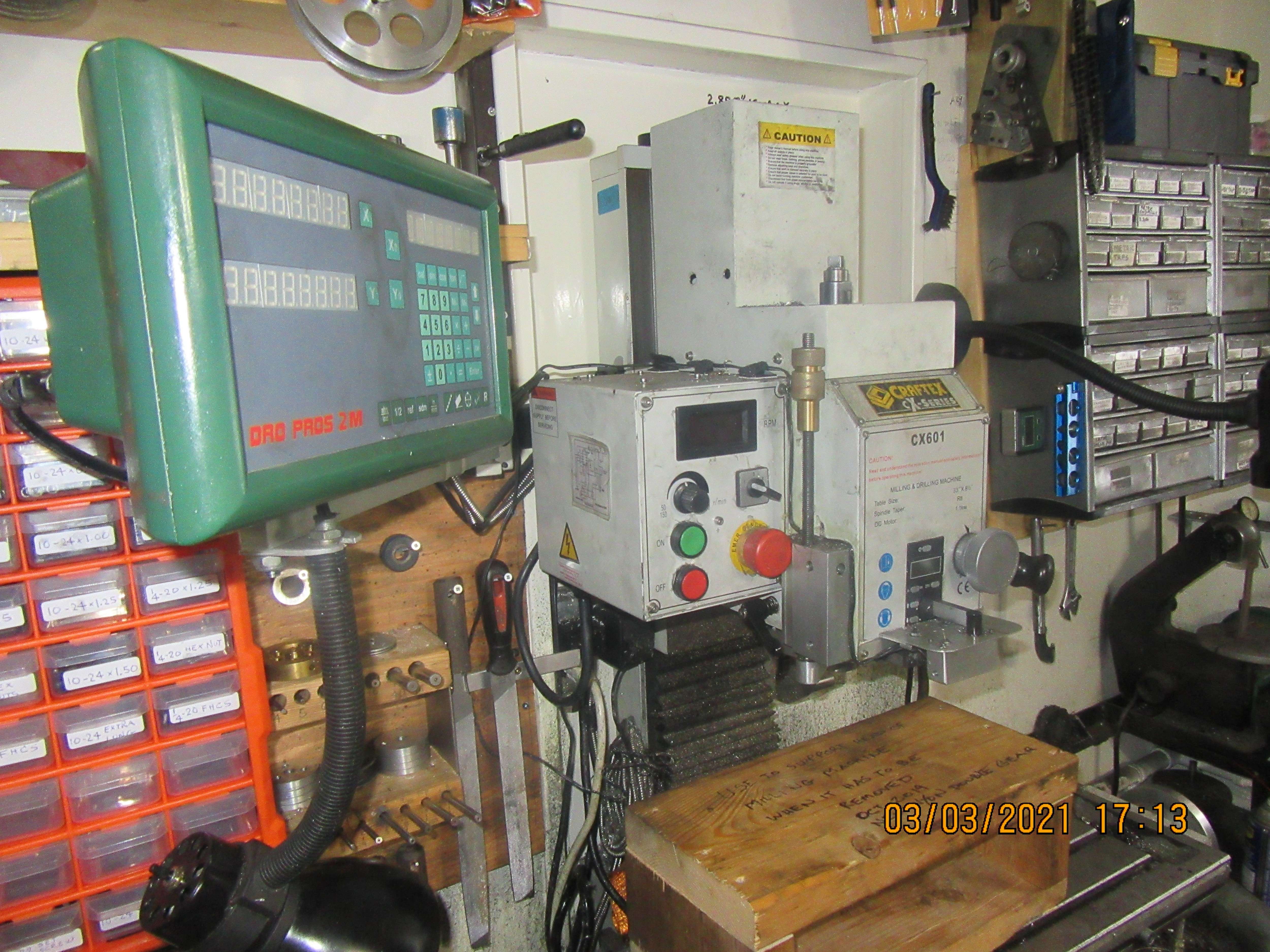
This shows the mill in it's home position, and as you can see there is no access to the back side of the box with the controls on it. However, since I very seldom get rid of anything, I hunted around until I found the wooden platform that I laid the head on when I changed the plastic gear in an earlier post. It seems that that is the simplest way to gain access to the back side of the control box, so by removing two large bolts I should be able to access the back of the control box.
ErKdrk.jpg
 
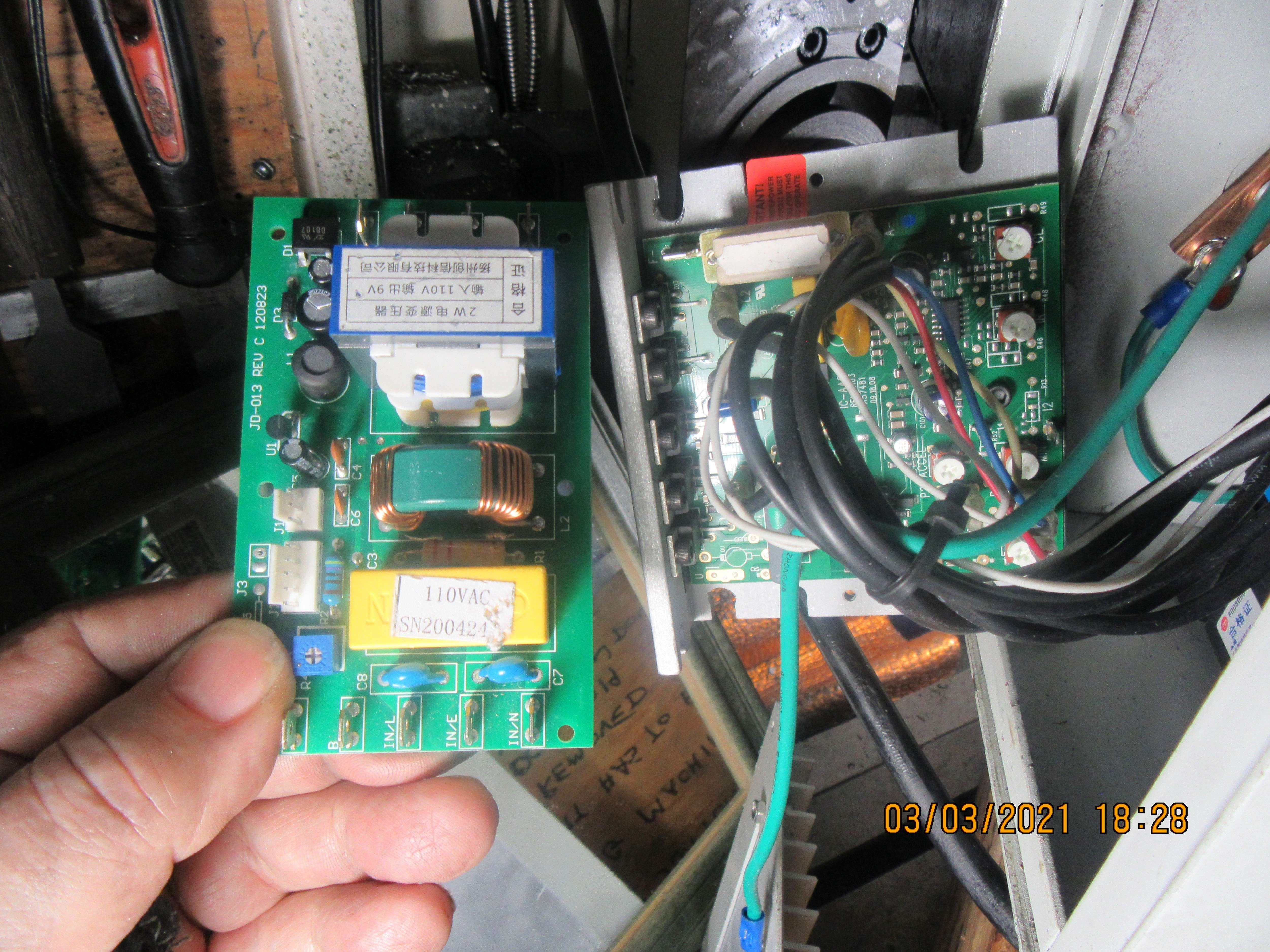
So, with the head dismounted and the back cover off the control panel---It looks like they may have sent me the wrong board. The one in the machine is considerably different from the one in my hand. EDIT-EDIT--a friend with the same machine as mine had his apart while changing it over to cnc controls. The control box has a second board setting underneath the top/inside of the control box which does match the board they sent me.
A5uBu2.jpg
 

Latest posts

Back
Top