Crankshaft grinding?

Home Model Engine Machinist Forum

Help Support Home Model Engine Machinist Forum:

This site may earn a commission from merchant affiliate links, including eBay, Amazon, and others.

cessna

Well-Known Member
Joined
Feb 28, 2010
Messages
183
Reaction score
4
Hi all, I am presently making a crank for a four cyl eng. I am using the conventional method of milling off the excess and mounting between centers to cut the throws. My question is what would be wrong with mounting the shaft between centers and somehow mounting a small grinding wheel to the cross slide, the grinder would be powered, with the lathe turning the shaft and the grinding wheel advanced between the webs to grind the throws.
Probably something obvious I am missing, but would love to hear your thoughts.
Terry
 
It would be the grinding dust eating your lathe. So it would probably work great, once. :)
 
I understand about grinding dust, the lathe would have to be protected, that is not hard to do.
Terry
 
Lakc said:
It would be the grinding dust eating your lathe. So it would probably work great, once. :)

I just wish people wouldn't make unfounded statements like this, it puts people off using a very useful method of machining.

I have done more than my fair share of toolpost grinding over many years, even on my lathe since it was new three or four years ago, and as of yet, it hasn't fallen in half or even changed 0.0001" in readings, and my ways are not scored or marked at all.

Anyone would think you pour bucketsful of grinding dust over your machinery, when in fact it is only tiny amounts, and a quick cover up takes care of that. It is no worse than overheated and hardened chips of swarf that you get on your machines every day, and no one ever says you shouldn't be doing that.

I have a 50 year old manual surface grinder, and the ways on that are almost as good as the day it was made.

So please, no more hearsay. Unless you have done it yourself, and had a machine ruined by it, how would you know?


John
 
Model Engien Builder Mag has been running an article on cam grinding, quite a bit of that info could be applied to cranks as well.

As Bogs says you are only taking off the last thou or two and if you were creating loads of abrasive dust then that suggests you are loosing far to much off the abrasive wheel which will be getting smaller as it traverses and giving a tapered finish. after grinding a jurnal or two you really should not be able to detect any change in the abrasive wheel dia.

J
 
I used to use a 40 year old cylinder grinder at a mower shop which all it done was grind and had no covers over the ways. No noticeable damage. Surely taking a tiny cut would produce tiny particles? What is the difference between a ground chip and a cut chip anyway? What makes it super bad for your lathe ways, is it just the size? How come crank grinding machines never have covers but they do have fluid? Sorry for all the question but I plan to make a tool post grinder one day. I think I agree with you John.
Brock
 
I forgot to answer Cessna's question.

What you are considering is perfectly feasible, in fact, I think it was John Stevenson that mounted a small bench grinder to his crosslide to do some cylindrical grinding on his Myford.

As Jason says, it is only used to remove tiny amounts, say 0.001" to 0.002" maximum, just to get a perfect finish.

The way you get the superfine feeds that are required is to set over your topslide by say 5 or 10 degrees and use that for putting the cut on with. Crosslide scale feeding really is too coarse to use for grinding.


Brock,

A toolpost grinder really is a nice piece of kit to have. I use mine mainly not for parallel finishing, but for grinding the tapers onto the end of control valve needles, and I can honestly say, I never have any problems with leakage.
On the other hand, I hope, in the not too distant future, I will have a large single crank that will require grinding.

I have mentioned these before a few times. LMS, in the US, do a range of very reasonably priced toolpost grinders.

http://littlemachineshop.com/produc...?critFast=tool+post+grinder&B1=Product+Search

Unlike the Hemingway kit for sale here in the UK

http://www.hemingwaykits.com/acatalog/The_Dynamic_Tool_Post_Grinder.html#aHK_202300


John
 
Cessna; nothing wrong with the idea.
like others have said this is the kind of stuff tool post grinders are made for.
I worked in a grinding shop for about a year
everything was flood cooled. grinding is a finishing operation. use it to take of the last few thousands,
you can get superior finish and tighter tolerances. Provided that you can control the machine and measure consistently in ten thousandths of an inch . you idea is a good one cranks have been ground by industry for decades at least . no reason not to do it in the home shop. yes practice good housekeeping and and keep all machine tool ways as clean and crud fee as possible.

It would be the grinding dust eating your lathe. So it would probably work great, once
tool post grinding is a tried an true method of removing the last bit of metal from a precision and or hardened part used by industry for decades. Machine tools die from neglect ,ignorance,apathy and abuse . Not being used and properly maintained.
tin

 
How about the commercially available diamond coated wheels.
You wont get any measurable abrasive contaminant on the lathe bed then?
Come in various widths dia`s grades?


Brian.
 
I would like to apologise for making an incorrect assumption then. I took the OP's request as one to hog out the entire crankshaft, not just finish the journals.

I have been going over this exact problem myself a lot lately, and while toolpost grinding does have its purpose, I have yet to see it applicable to model crankshafts. The main reason, in my conjecture, is that with a method of precise metal removal is spoiled (or spoilt for our British friends) by the spring induced with the crankshaft held between centers, and the imbalance of the crankshaft leading to an out of round journal. Both of which, along with proper flood cooling, seem to be the subject of considerable design effort on the part actual crankshaft grinders.

I understand that it will work, but with both turning and grinding, both methods are finished with fine emory cloth anyway, so I just dont see it as a value added procedure.

I would like to build a dedicated crankshaft grinder. With counterbalanced offset chucks. And its quite possible my next project will incorporate that along with a crude crankshaft forging die. Any way you cut it, the making of the crankshaft seems to be the least fun part of the job.
 
Gentlemen,
Over the course of time I have made cranks by almost every conceivable process, cut from roundstock, cut from flatstock, fully lathe turned, partially milled first and by fabrication.
Each process was a learning procedure, how to hold the material, what type of tools to use, how to support the stock, how much it would warp when silver soldered and most importantly if there was any warpage could the crank be saved.
Depending on the type of crank you're making, single, double, 4 cylinder, 8 cylinder or more one of the most important elements is how rigid your tooling is. When you start turning off center you generally have to deal with center supports for the crank and this means you have already lost some of the rigidity of your setup.
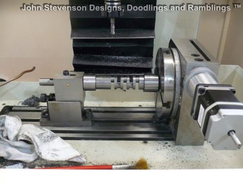
The best way I have found for making multi-cylinder cranks is to mill out as much stock as possible before turning. Trying to 'turn' a piece of stock off center with a long bifurcated tool is nerve wracking. As you slowly feed the cutter in listening to the 'kachunk, kachunk, kachunk and just waiting for the tool to dig in and knowing you've go 4 more of these to do is quite daunting for even the most skilled machinist. That's why I like to mill out as much stock as possible, allowing for cleanup, spring and possibly some warpage.
Once you get down to say .004 remaining stock you should switch from the bifurcated tool to a narrow left hand and right hand tool. They should be small enough at the tip to allow a small amount of overlap to clean up the entire journal. The critical part of this operation is matching up the 2 cuts and for that matter measuring the first cut so you can get it to the finished diameter. I have made narrow tipped extensions for my mikes because I'm not a big fan of calipers for accuracy.
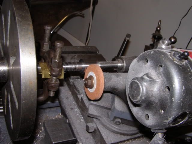
The other way to finish is to grind, which is in answer to the original question. I have finish ground several crankshafts. The nice thing about grinding is there is virtually no tool load (when small cuts are made) and therefore no spring. With the grinding wheel dressed and square you can touch the work and then move back and forth to clean up the whole journal, no tool changing and no cut matching.
As far as the grit goes, cover your exposed ways with whatever material you desire, aluminum foil, rags or paper towels soaked with oil or even make up some thin neoprene sheet covers.
I have never used coolant because first, I don't have a collection system, second it's a mess and third if you're only taking .0005 per pass the material just doesn't burn.
A dedicated grinder would be nice but as with a cam grinder, how many cranks and cams are you going to make in your lifetime?
Sorry for the long-winded reply for just a couple of sentences but sometimes a little more information helps out with understanding the situation.
George
 
I would say that a ground part does not need finishing with emery cloth unless you have been using a very coarse wheel and fast feed.

Also as George says there is less pressure on the part when grinding than trying to take a small amount off with a lathe tool so less chance of spring, vibration or distortion.

J
 
Hi Terry,

Do you know the Sherline CAM Grinder?

See...


Cheers,

Alexandre
 
If I read you correctly. The idea is to drive the grinder with a belt off the chuck. A few things to keep in mind while you figure out a plan. Grinding wheel speed is about 5-7000 SFM, work speed is low 200 rpm<, A wheel needs to be large enough to clear the counterweighs and still reach the journal so a 5+" wheel mounted on a 5000 rpm spindle is needed. And all this needs to be mounted on the crosslide.

Here is my Myford which I use for grinding. That is a 17,000 rpm Dumore TP grinder, feed is with the compound.

corlissproject025-1.jpg


The grinder has 1/14 Hp and is fully loaded at .0003 doc. I added an extra set of gears to the leadscrew so the advance is .0009 per rev.

This setup would not work for crankshaft grinding as the wheel is 2" which gives only .4" clearance to the spindle. not enough to clear the tailstock holding.

In use a crankshaft grinder has a adjustable follow rest for the journal being ground, the wheel feed roughs the diameter, and the follow rest is adjusted to bring it to final size. We often think of steel as being so ridgid, but a 500Lbs 60" long crankshaft is like a noodle between centers of a crankshaft grinder and needs to be supported while being machined.
 
Jasonb said:
I would say that a ground part does not need finishing with emery cloth unless you have been using a very coarse wheel and fast feed.

In full size practice, the final polishing is done with a powered bow type belt sander. Surface finish definately counts on a crank journal. They even go so far as to match the grind and polish rotation to the actual rotation of the crank while in use.
Also as George says there is less pressure on the part when grinding than trying to take a small amount off with a lathe tool so less chance of spring, vibration or distortion.
You have less deflection from the cutting tool, but you still have deflection from the centers, which changes when the part heats up.

gbritnell said:
A dedicated grinder would be nice but as with a cam grinder, how many cranks and cams are you going to make in your lifetime?
I hope to be doing this for a long time :)
Sorry for the long-winded reply for just a couple of sentences but sometimes a little more information helps out with understanding the situation.
You have nothing to apologise for. The sharing of ideas, experiance, knowledge, and conjecture are what these forums are all about. I wont stop learning, ever. :)
 
Lakc, I put a link in your crank holding thread that may be of use.

J
 
Strictly IC magazine has plans and articles in their back issues for Crank Grinder and some Cam Grinders.

Ray
 
Not grinding but we are away at the Midlands show in the UK and are demonstrating milling a crank on the CNC.

crank1.jpg


Not too clear a picture as it's face on but there are 5 journals all at 180 to one another, forgot the mains :D

The 'crank' rotates on it's main centres in the RT and as it does it moves the Z up and down in time to the Y going forward or back to the centreline of the tool is always on the centreline of the pin.

John S.
 
John Stevenson said:
Not grinding but we are away at the Midlands show in the UK and are demonstrating milling a crank on the CNC.

Are you generating code with a 4 axis CAM software or manually?
 
Wow, great responces to my post, a lot of great info and pics. Alexandre I have not seen that setup before, I have a Sherline lathe and mill I use for small work.
Thank you
Terry
 

Latest posts

Back
Top