Clutch---Again!!!

Home Model Engine Machinist Forum

Help Support Home Model Engine Machinist Forum:

This site may earn a commission from merchant affiliate links, including eBay, Amazon, and others.
Coilmotorworks---I don't have too many old "Rumley Oil Pulls" (whatever that is) laying around my garage. However, I do react well to good clear sketches, explaining what you are suggesting.----Brian

Brian, here is a drawing of a multi-plate type clutch for your application. It's actually a single plate clutch but the rest is based on the multi-plate concept.

If you want more details I'd be happy to supply the models etc. for it.

View attachment Clutch.pdf
 
Trumpy---Thank you. Thats a great design. I have stashed it away on my hard drive with my other clutch files.----Brian
 
Today we had our first tryout of the new clutch. It looks really good in the movie, but only seconds after the movie was made the clutch started to bind up. I'm not sure why---haven't torn anything down to check yet. If this clutch design doesn't work out, then I'm going to give up on clutches for a while.
 
I tore things down and it seems that some Loctite had migrated to where it shouldn't have when I assembled things the last time. After a bit of clean up and reassembly, things appear to be okay. The clutch is up on the lathe again wailing away at 500 RPM. If it does this for half an hour without any more binding, I think its okay. I'll let you know when the half hour is up. Then I will run it for half an hour with one of my air/steam engines to see if there is any binding thats being hidden by the lathe, which is very powerful.
 
Last edited:
Barrington---The spring just sets in there between two faces. That is the only constraint imposed on it. Yes, you are correct. This makes the clutch somewhat "uni-directional", depending on whether the spring is wound clockwise or counter clockwise. This second test I curently have underway is turning in the opposite direction, brecause I thought of the same thing you suggested. In the first test, the parts were rotating "against the spring". In this current test, the parts are turning the opposite direction. As for heat causing clearances to change and bind, it shouldn't happen. Everything that turns is supported on sealed ball bearings. The only non bearing contact is between the clutch cone and its receiver. The cam/lever pushes against the inner race of the outer bearing, but that inner race doesn't turn. The pressure is transferred to the wooden cone thru the balls and the outer race.
 
Here we have it after 1/2 an hour at 500 rpm. It still engages and disengages slick as a whistle, and no binding apparent.---I slipped the belt off and turned it by hand to check this. Nothing was hot, nor even warm to the touch. I think Barrington nailed it with his comment about the spring direction.
CLUTCHAFTER30MINUTESAT500RPM001_zps07e6dec1.jpg
 
Here is a neat little video of the clutch being driven by one of my very earliest steam engines. It seems to take very little power to run this clutch, as can be seen here.
 
Barrington---The spring just sets in there between two faces. That is the only constraint imposed on it. Yes, you are correct. This makes the clutch somewhat "uni-directional", depending on whether the spring is wound clockwise or counter clockwise. This second test I curently have underway is turning in the opposite direction, brecause I thought of the same thing you suggested. In the first test, the parts were rotating "against the spring". In this current test, the parts are turning the opposite direction. As for heat causing clearances to change and bind, it shouldn't happen. Everything that turns is supported on sealed ball bearings. The only non bearing contact is between the clutch cone and its receiver. The cam/lever pushes against the inner race of the outer bearing, but that inner race doesn't turn. The pressure is transferred to the wooden cone thru the balls and the outer race.

So you are saying it works well in both directions?
Because I am thinking of using a steam engine to run a small watchmakers type lathe, just for demo's and shows and things, and I would want a clutch that would work both ways.

John
 
Yes---There is a high coefficient of friction between wood and steel, much lower between steel and steel. A hardened washer set in the bottom of the oak cone counterbore would let the spring ride against steel on both ends, with a much lower chance of wanting to "grab" and bind on the end of the spring.
 
I haven't run off, and I haven't abandoned this project. Since I last posted, I've had an "Almost Flood", picked up a bunch of design work, and managed to catch some kind of nasty flue----All simultaneously. That, along with machine shop burnout has kept me from adding anythng interesting. I am also having issues with my Odds and Ends engine that I recently completed---something to do with carburation, I believe. I will add more when I'm feeling a bit more human, and have sorted through some of the issues.---Brian
 
Hope your feeling better. I've been in clean up shop mode the past week. Hope to make chips tomorrow.
 
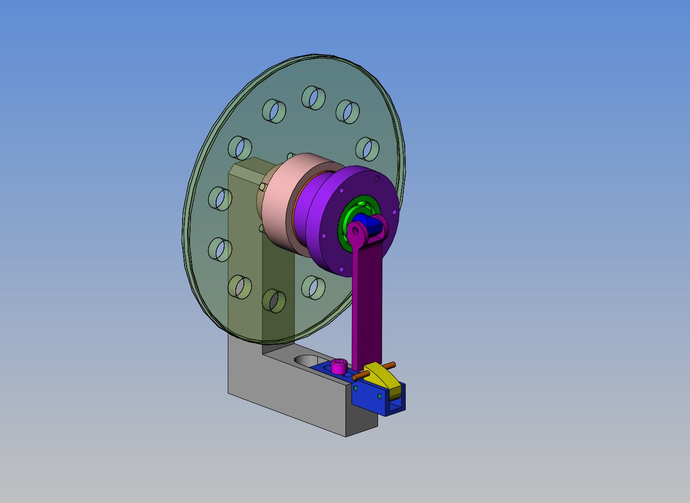
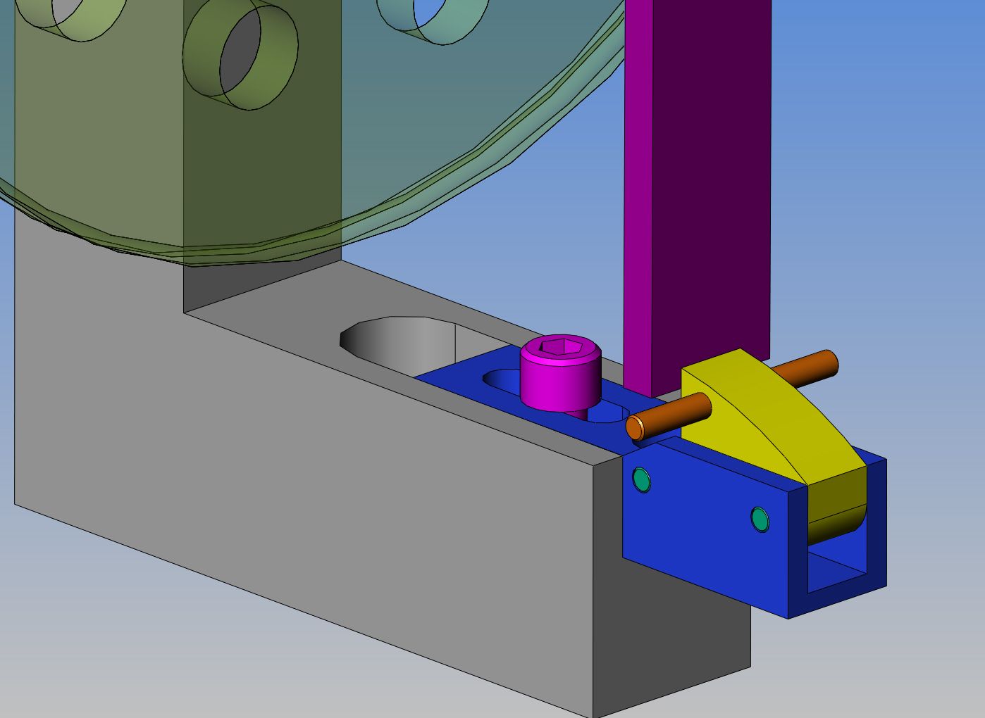
I think I'm going to live!!! Felt well enough to play with my clutch design this afternoon. I have come to realize, after playing about with this thing, that I have to have some means of holding the clutch engagement lever in place, other than my thumb.---And it has to be adjustable, to compensate for clutch wear and to adjust the force put on the cone. I'm not sure how well it shows up in the attached .jpg, but the dark blue part has a slot in it for a 1/4" unc bolt, and can be moved in a slot milled in the grey frame member to adjust position. The yellow trigger is spring loaded "up" with a compression spring underneath it. It pivots around the green outer 1/8" dowel, and is restrained from springing completely out by the second 1/8" green dowel that is closer to the grey frame. The bronze colored 1/8" cross shaft thru the yellow trigger is something to push down on to release the clutch engagement lever. I have built the 1/4" thick by 6.75" dia. pulley and bolted it in place.---Haven't drilled all the holes in it yet though.---The 12 holes have no real purpose, but if you don't put them in, its very difficult to see what is rotating and what isn't in a video.
 
Hi Brian,
this is a nice set up you have, I think you should consider one thing
having 1 to 1.5 degree angle different between your friction point and frintion disck

having all the same angle as soon that this wood will get smooth because of clutch slipering it wont work like a used Vbelt when all the sides rub it' slips
by having a different angle you would eliminate this.

now you have a nicely finish pieces of metal polishing wood when they mate
all your friction is gone. other wise you would would be using that peaces a few thow at the time
hope my french didnt interfer to mutch with my translation
 
Luc--the trouble with two different angles is that you end up with a line contact, which almost immediately wears away. With both angles the same, you get full face contact, and as the face wears the cone just sets farther into the cup. Thats why the adjustment slot is there in the blue part. As the clutch wears down and begins to slip, the bolt in the blue part is loosend up and the whole latch mechanism can be moved in a bit to keep pressure on the cone.
 
Last edited:
like a used Vbelt when all the sides rub it' slips

I thought a worn V belt slips (sometimes with noise) when the sides get so worn that the belt rides on the bottom of the pulley's Vee. Then the wedging action is lost.

Jordan
 
I thought a worn V belt slips (sometimes with noise) when the sides get so worn that the belt rides on the bottom of the pulley's Vee. Then the wedging action is lost.

Jordan
Yes Jordan, you are correct. That is why, in the design of this clutch, there is a lot of room between the end of the wooden cone and the inner bottom of the aluminum cone shape that it fits into. Once those two surfaces touch, the clutch loses about 95% of its eficiency.
 
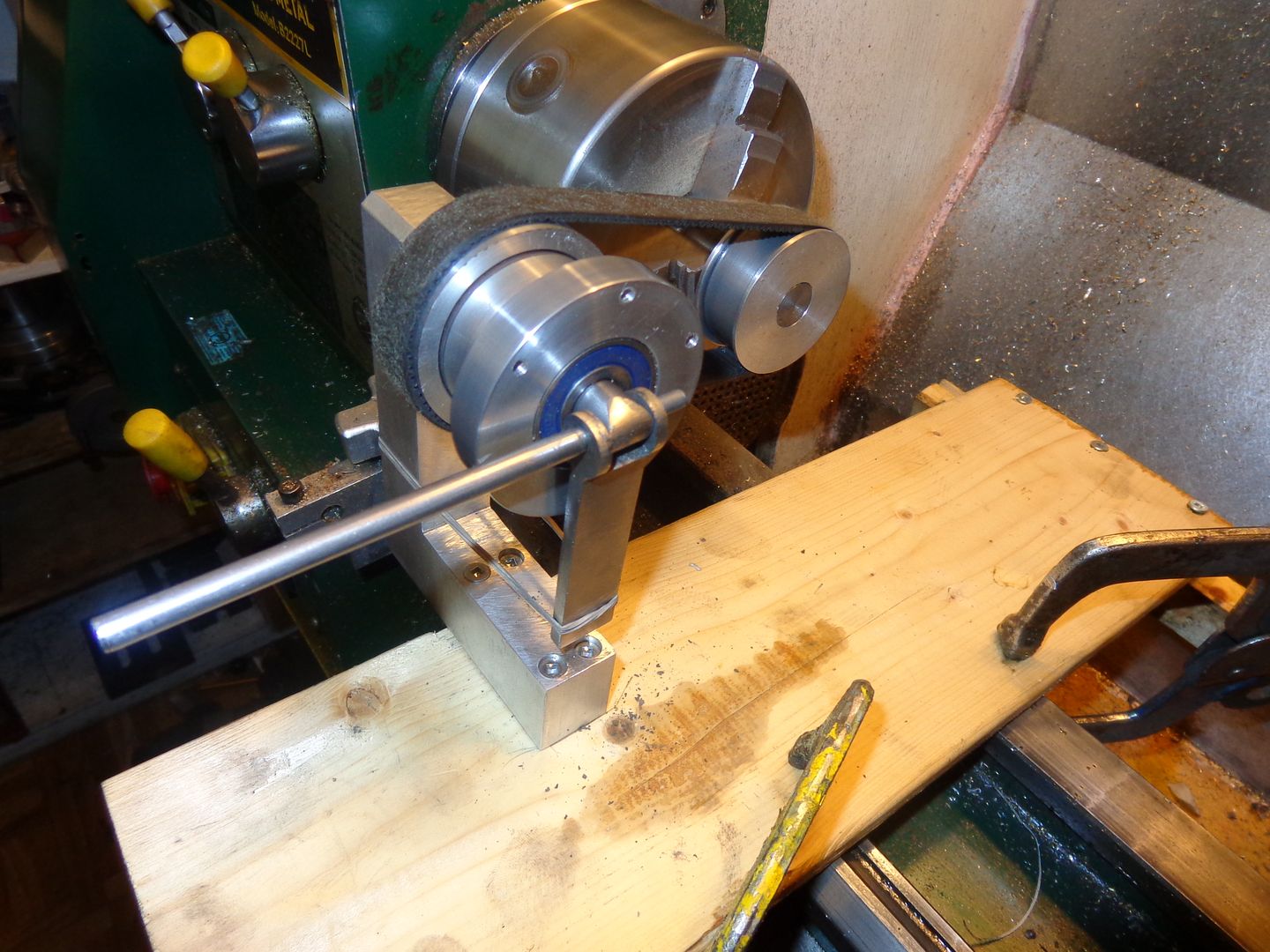
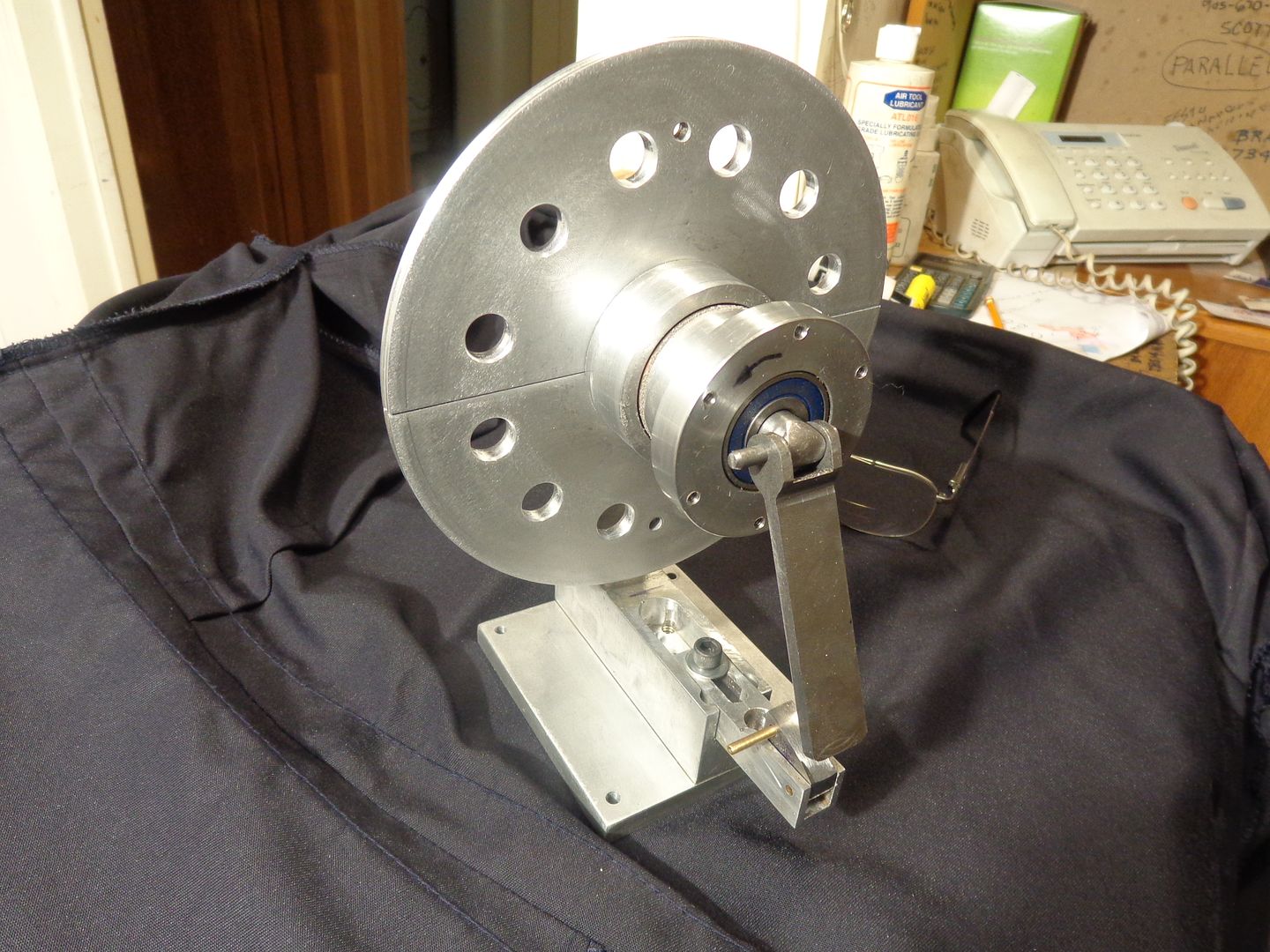
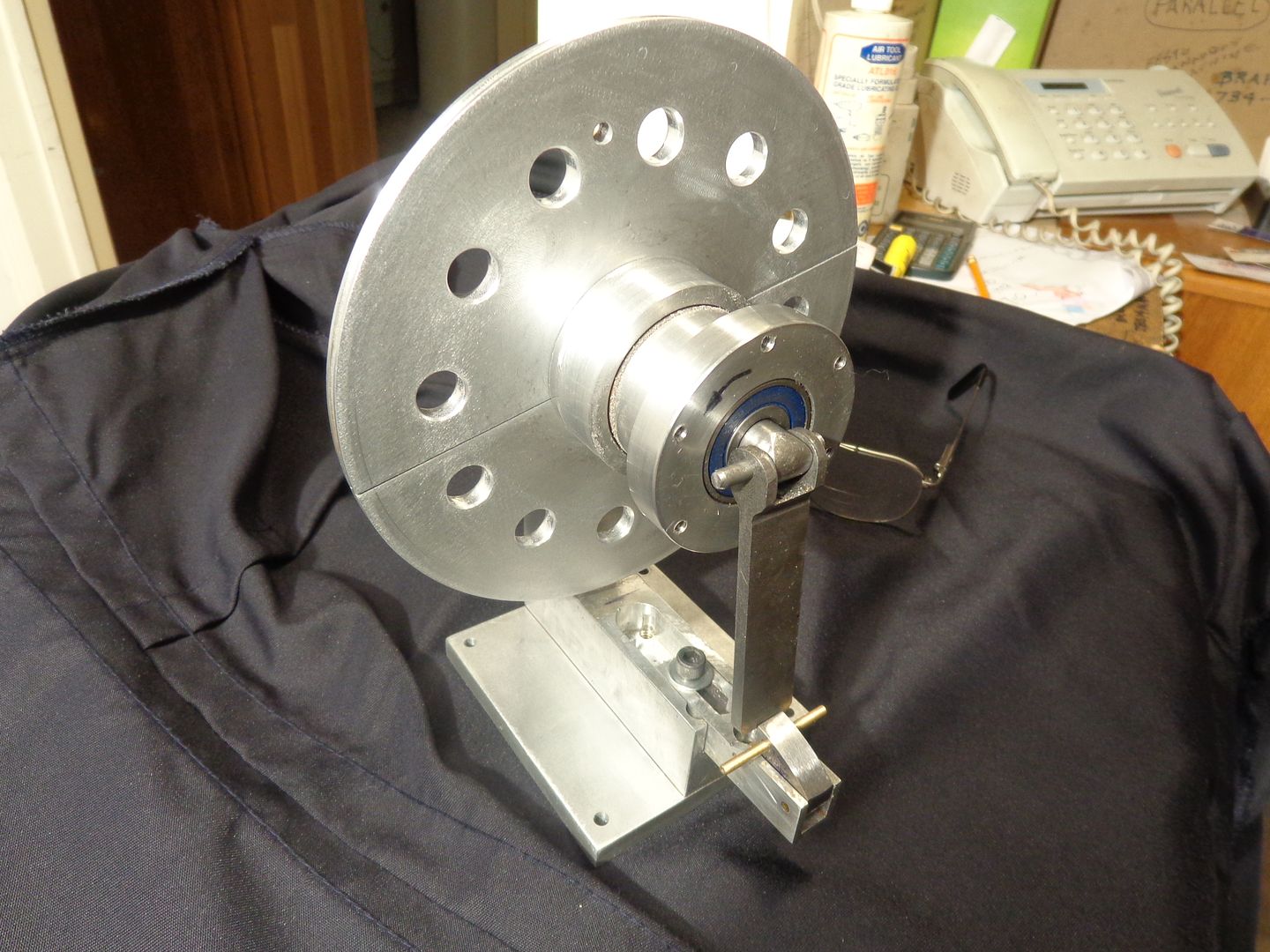
I finally found some time to fully assemble this clutch, make the large pulley, and machine the spring loaded trigger latch, and make a base. I must say, it works fine with no noticeable binding at all. The adjustable latch not only holds the clutch cones fully engaged, but since it is adjustable, I can set now much force is applied between the two friction cones when the clutch is engaged. It also enables me to adjust for any wear that occurs. I have put up two pictures, one showing the latch position when the clutch is engaged, and one showing it with the clutch disengaged. The large pulley is driven by a 0.100 rubber o-ring drive belt from the engine. The smaller pulley closest to the latch can either drive a flat belt off the smaller diameter, or can have a larger pulley bolted to the ring of holes in the larger diameter.--Now I have to get back to my Odds and Ends engine and do some carburetor work, and perhaps we can have a demo video. I'm not certain at this point if the Odds and Ends engine is going to have enough power to run the sawmill or not. Jim Dunmyer has built one of the sawmills, and his smaller engines don't have enough power to run it properly.---We'll see!!!!!---Brian

 
Last edited:
The Centrifugal Clutch system used on many early International tractors and 6hp stationary engines, may also be an interesting research project sometime in the future. I am pretty sure I have a pic of one in an old IHC catalogue. Will post when I find it. If I remember correctly ... no springs and one brass bearing ... but don't quote me lol. Meanwhile I will post a very non-commital pic of one in use to wet the appetite.

Geoff

clutch.jpg
 
The clutch is finished, and it works very nicely. There is a video of it in operation in my post about "Model Sawmill Dreaming". For anyone wishing to build this clutch, the attached link will get you a free download of all the detail drawings in pdf format. When you click on the link, a page will open. Scroll down to the bottom of the page and choose the "slow download" option. Its not really slow, and it won't cost you anything.-Its not really slow, and it won't cost you anything.----A word of warning though--When you download it, you will be offered a whole damn bunch of junk offers. Just hit "Decline" every time that happens, and eventually you will get to the download---Brian
http://www.filefactory.com/file/1yrhedyn4p6d/CLUTCH_DETAIL_DRAWINGS.zip
 
Last edited:

Latest posts

Back
Top