Building Rudy's Steam Tractor

Home Model Engine Machinist Forum

Help Support Home Model Engine Machinist Forum:

This site may earn a commission from merchant affiliate links, including eBay, Amazon, and others.
Cross Slide Guide

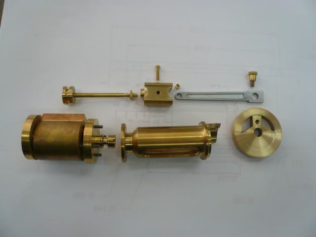
For the cross slide mechanism, I’m using Doug Lanum’s design as described here. Doug’s design is more rigid and looks more like the prototype engine than the one in the Village Press plans.

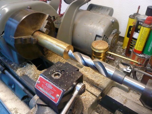
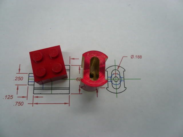
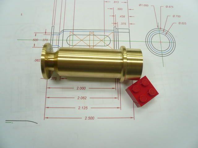
I did all of the lathe work in one set up. The finished cross slide guide is 2.500” long. I started with a 1” piece of brass rod and drilled and bored it 5/8”D x 2.125” deep.
P1040614.jpg


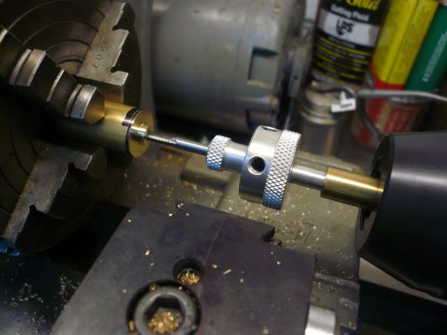
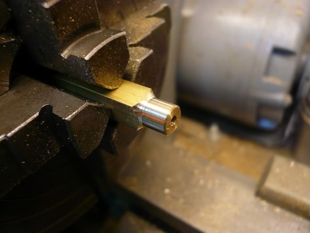
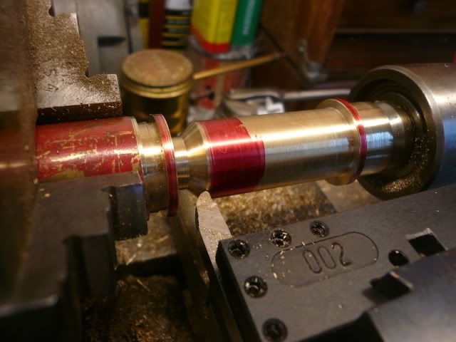
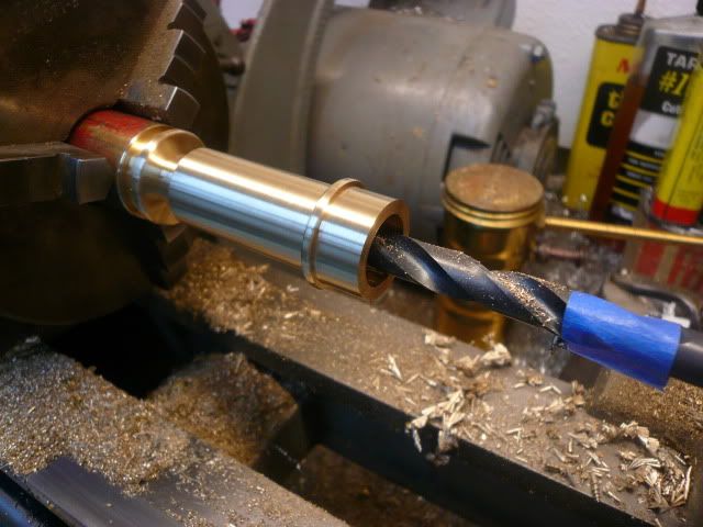
I then added the live center for support and turned the outside details. I used the compound set at 45 degrees to do the angle detail.
P1040621.jpg


Round the flange and decorative ring with a file and complete the center bore by drilling a 3/8” hole for the valve rod/packing gland to pass through.
P1040623.jpg


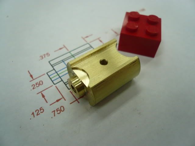
Part off and the lathe work is finished.
P1040630.jpg


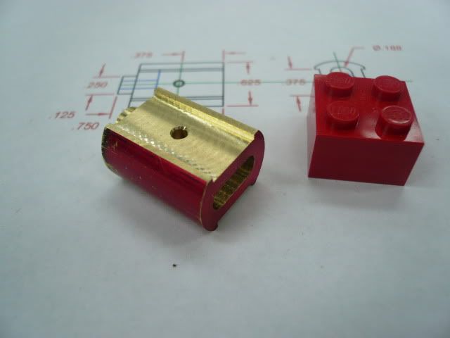
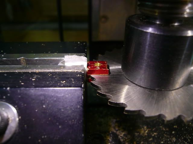
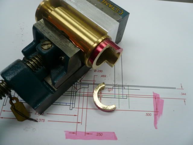
The rest of the guide is done on the mill. The first step is to saw off the excess material on the end (faster than milling).
P1040797.jpg


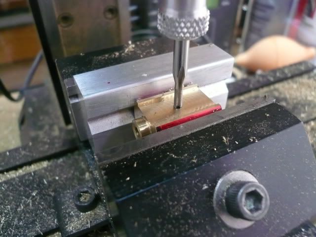
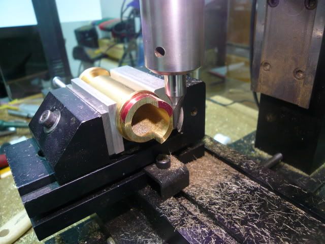
Then clamp in the mill vise and mill the flat where the cross slide guide mounts to the horn plate.
P1040798.jpg


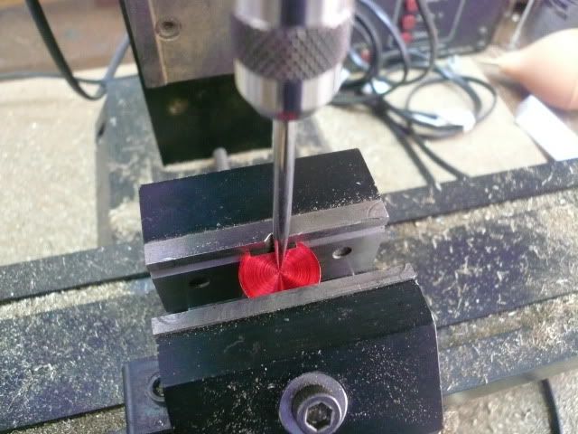
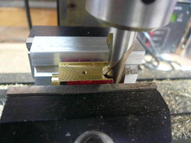
Without moving the part in the vise, switch to a 1/2" mill and mill the end contour.
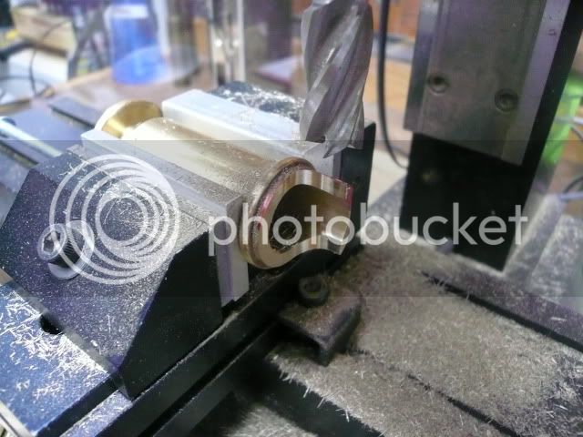
P1040811.jpg


Rotate the part 90 degrees to drill the two 2-56 mounting holes and the side openings. I used an adjustable parallel to get the correct rotational setting.
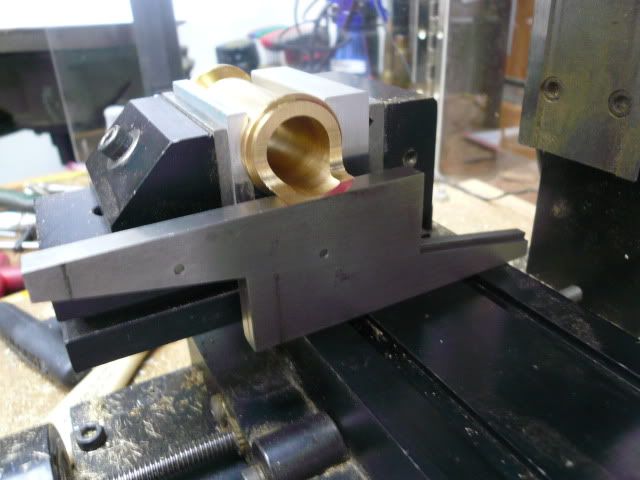
P1040822.jpg


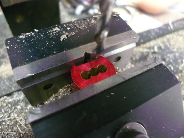
Drill and tap the two 2-56 mounting holes.
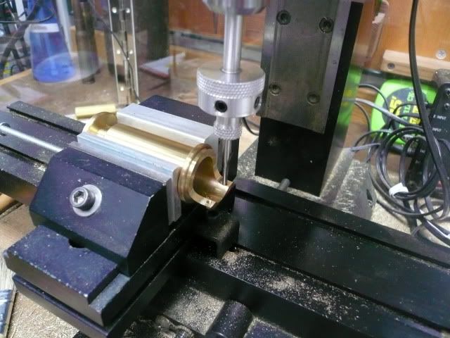
P1040826.jpg


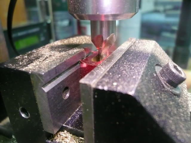
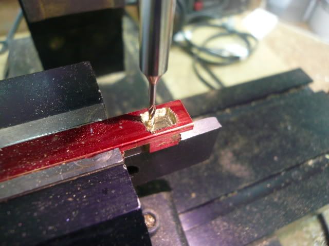
Then cut the side openings with a 3/8” mill. I did this by taking light, full cutter-width passes through the top surface and then on through the bottom.
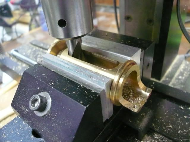
P1040834.jpg


Using the cylinder head holes as a guide, drill the four mounting holes in the flange.

That finishes the machine work. The sharp edges on the sides and near the mount will be rounded and blended later.
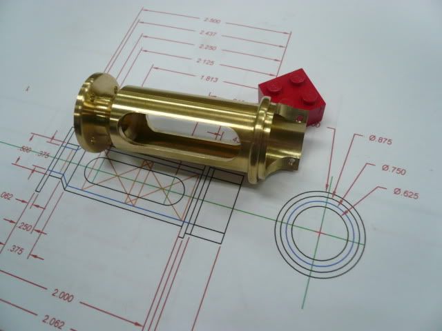
P1040844.jpg


I had planned to use 2-56 brass hex head screws for assembly, but discovered that I didn’t leave enough room to get them in the holes. Drat!

There are a couple of ways to work around the problem. One is to use studs. That’s what I’ll do if I can find some decent scale 2-56 nuts. The other is to just enlarge the holes enough to get the hex head screws in. This should be an okay work around because the boss on the cylinder head provides the registration.
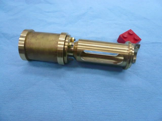
P1040892.jpg


Two other things to consider if you make this: one, make the flange flat where the bolts land (Mine has a slight slope. It’ll be okay, but would be better flat.) and two, leave another quarter inch on the end where the cross slide guide screws to the hornplate. A little extra length there will allow for a nicer transition between the guide and the hornplate.

I think this is going to be a very noticeable enhancement to my tractor and just want to thank Doug Lanum again for sharing the idea. If you’re out there Doug…Thanks!

Dennis


Beautiful piece of work Dennis.
It came at a good time for me. I was feeling a bit down with my lathe...seeing your work keeps me motivated.
 
FWIW, I found some scale brass 2-56 nuts at a model train hobby shop a while back-- might want to look there if you go the studs-n-nuts routine.

 
What a wonderful thread,
great pics and write up
top notch :bow:

regards
Andy
 
Excellent series of photos. Thanks for taking the time to shoot and post them.
 
Hi Guys,

Thanks for the comments. Always encouraging to know you're following along. I'm continuing on with the power train components. Today it's the cross head.

Cross Head

The Cross Head is made from a 7/8” long, 5/8” diameter piece of brass rod. First turn a 1/4" dia. x 1/8” boss on one end, then drill and tap 5-40 to accept the piston rod (Note: Rudy’s plans call for a 1/8” dia. piston rod with a 4-40 thread, but I used 5-40 because it’s a perfect thread for a 1/8” rod).
P1040972.jpg


That’s it for the lathe work. The rest of the cross head is done in the mill.

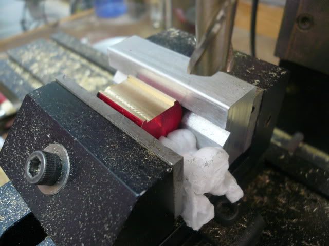
The first step is to mill flats on each side of the guide. The flats are 3/8” wide 3/16” up from the center line. I used an aluminum vee to avoid marring the surface of the guide and a 3/8” mil to cut the flats.
P1040984.jpg


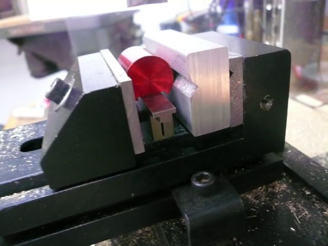
After the first side is milled, turn the part over and mill the other side. I used an adjustable parallel to help align the part so the two flats are parallel.
P1040981.jpg


After the second flat was milled and before taking the guide out of the vise, I drilled and tapped a 4-40 hole for the cross head pin (Rudy calls this a “gudgeon”).
P1040986.jpg


The next step is to mill the cavity for the connecting rod. The cavity is 7/16” long x 3/16” wide and 9/16” deep. I located the center with a wiggler and then worked off of it to mill the slot.
P1040993.jpg


It’s a lot faster to drill than mill, so I used a 3/16” drill to remove most of the material before milling.
P1040997.jpg


After drilling, I used a 3/16” end mill and lots of shallow passes to get to the final dimensions.
P1040999.jpg


I'm intimidated by deep, narrow slots but it turned out okay.
P1050004.jpg

P1050006.jpg


At this point the cross head is fully functional, but I decided to embellish it a little (and make it more like the prototype) by shaping the ends.
P1050009.jpg


The finished cross head.
P1050018.jpg


Regards,
Dennis


Great looking job Dennis! Also the writeup is phenomenal. When this is finished it would be neat if this thread could be put on cd and sold to others wanting to build this project. I'd definitely buy it. I have Rudy's plans for this but too many other projects going on right now to even try and start it but someday I want to build my own steam traction engine. I really like the gear reduction you did as there is nothing worse than seeing a really nice model that moves way to fast for the scale it is built in. I look forward to seeing a video of it running when it is finished. Keep up the good work and thanks for sharing.
 
I have Rudy's plans for this but I think to start the project next year...I have to do more practice and change my lathe...!!!
Great Job...really well done th_confused0052
Paolo
 
japcas,

I can't think of a quicker way to turn a hobby into a job than to try and make money at it. :D

You're right about scale model speeds...ghart and Doug Lanham gave me a "heads-up" early in the build or I never would have thought of adding the extra gears.

I appreciate your comments. I hope you'll post some of your projects.

Paolo,

I've seen your work...I don't think you need more practice or a new lathe! Maybe just the time to work on it. When you get started on your tractor, please share it with us.

Regards,
Dennis

 
You sure are making a great job of it, Dennis. Fine work, and the write up is appreciated!
Watching your progress with interest.

Dean
 
Good job Dennis Thm: - not just OK like you said!

Regards, Arnold
 
Guys,
Thanks for the positive comments. They're much appreciated.

Cylinder Mounting Bracket

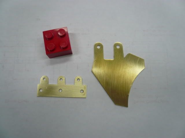
The cylinder mounting bracket is a two piece sheet metal assembly. Layout and cutting of the parts is the same as shown in previous posts.
P1040908.jpg


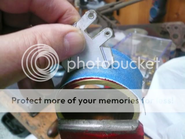
To get a smooth concave cut on the bracket, I rough trimmed it and then sanded it on an off-cut from the boiler casing.
P1040901-1.jpg


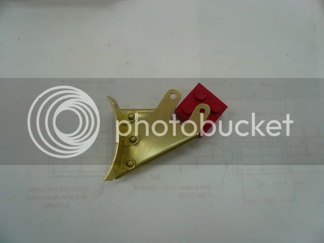
The lower part of the bracket was bent on the off-cut and clamped to it to mark the locations of the rivet holes.
P1040948-1.jpg


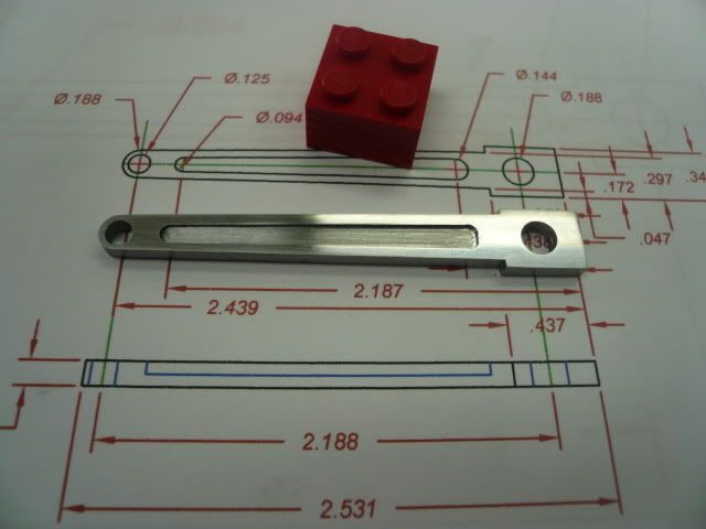
Connecting Rod

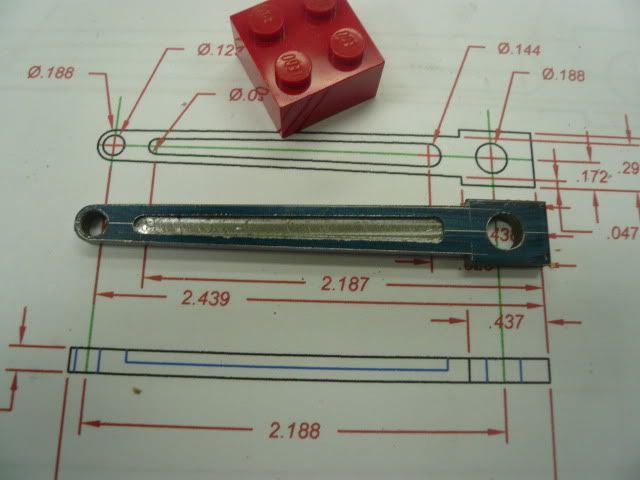
The connecting rod is made from 1/8” steel.
P1050093.jpg


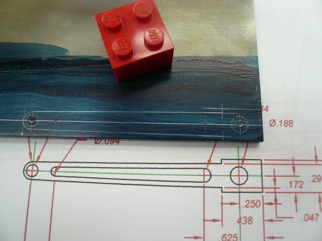
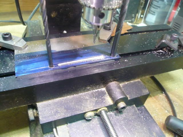
The connecting rod has a decorative inset. Since the edges of the inset are parallel to a line tangent to the two holes, I drilled the holes and then used drill bits pressed against the T slot to align the inset to the mill table. I milled one edge and then moved the plate to align the other edge and milled it. This alignment method is a variation on an approach Bogstandard showed in one of his early posts.
P1050096.jpg


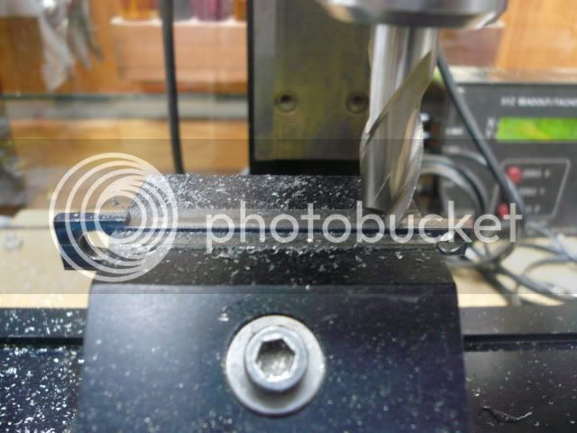
I had planned to use the same alignment method for the edges, but my mill vise is too short so I had to align the part using the layout lines.
P1050100.jpg


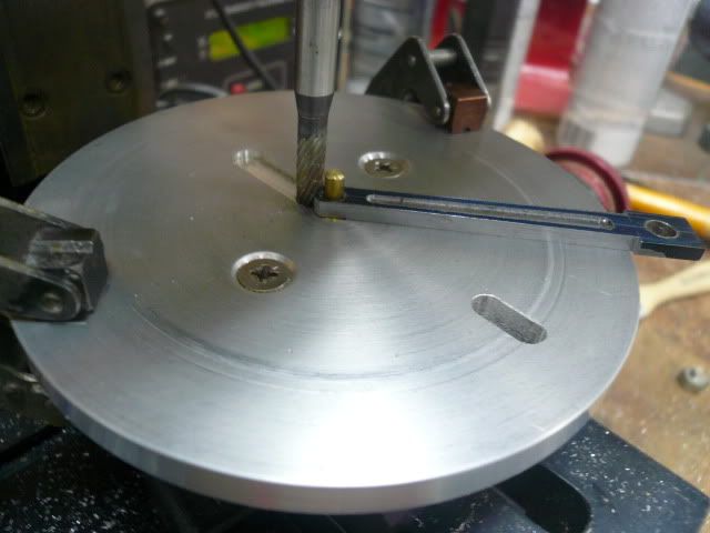
The end was rounded on the rounding table using a rotary file instead of a mill. Using a rotary file is a tip from mklotz and it really helps to reduce the pucker factor on this operation.
P1050109.jpg


P1050112.jpg


After machining, the connecting rod was polished using 320, 400 and 600 grit paper on a flat plate.
P1050133.jpg


The inset will be painted so I left it at 320. The “engine” parts of the tractor are almost all complete. I haven’t shown fabrication of the piston, but it’s a straight forward turning operation. The valve and eccentric are still to be done.
P1050187.jpg


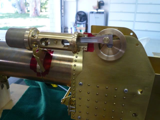
Here are the parts in a trial fit on the tractor.
P1050209_edited-1.jpg


You might notice I also added some rivets on the horn plates to represent cross stays. I think they add some interest to what was basically a flat piece of brass.

Dennis
 
Sweeeeeeeeeeeeeeeeeeeeeeeeet! :bow:

I really like the sheet brass work, I'm working with the stuff this very minute... so you'll have at least ONE person who likes all those rivets. Once they're painted over, they'll stop being a 'feature" and fade into 'texture'.
 
Nice nice work! Love the connecting rod. Thanks also for all the great build detail. Very helpful.
 
Very well done indeed Dennis ! Thm:
Regards, Arnold
 
Lovely work Dennis and a great write up, ........... thanks 8)

CC
 
Thanks for the encouragement, guys.

Vernon, I hope you're right re:
all those rivets. Once they're painted over, they'll stop being a 'feature" and fade into 'texture'.
I'm hoping for a first reaction of "Wow, nice engine." rather than "hey, look at all the rivets."

Continuing with the build:

Valve & Linkage

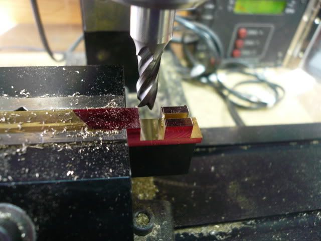
The valve is made from a piece of 1/4" x 1/4" brass and is 1/2" long when finished. I laid it out on a 3” piece of stock and did all the machining before cutting it loose as a final step.
P1050252.jpg


That included milling the 3/16” wide by 3/64” deep exhaust cavity on the bottom side.
P1050255.jpg


The exhaust cavity came out a little sloppier than I’d like. I think because I milled the outline first and then cleaned up the center. Better practice would have been to clear the center, leave material around the edges and clean that up last. A lesson learned. Here’s the completed valve and the valve spindle.
P1050267.jpg


The valve spindle is made from 3/32” brass rod. The spindle section is turned down to 1/16” and the other end is threaded 2-56.

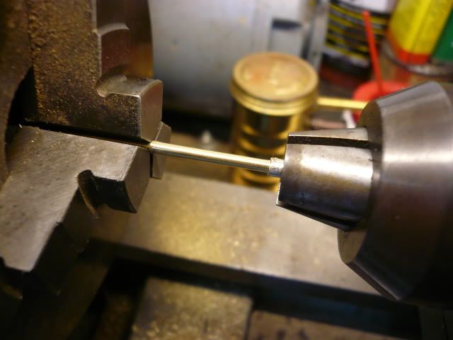
I had no luck turning the spindle (it kept bending). So instead of turning, I supported the free end in a piece of 3/32” ID tubing held in the tailstock and used a file to reduce the spindle to 1/16”. I also found out that you can’t thread 3/32” rod to 2-56. The rod is 0.0938” and a 2-56 thread wants 0.0860”. In order to thread the spindle, I left a little extra length as a bearing and filed a section to 0.086”, then cut the bearing part off and threaded the rod to 2-56.
P1050533.jpg


The next item in the linkage is the spindle eye. It’s cut from a piece of 1/4" square stock. Turn, drill and tap 2-56,
P1050218.jpg


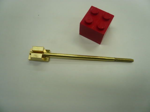
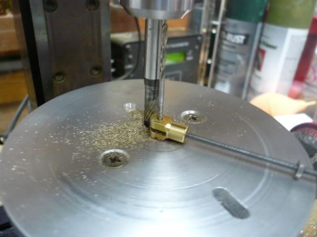
then cut off and clamp in the mill (the bits of paper protect the finish on the turned section). Drill and tap 2-56 for the cross pin screw. After tapping, I counterbored half way through with a #43 drill to allow clearance for the screw. Then I used a 1/16” slotting saw to cut the slot for the valve rocker.
P1050229.jpg


Round the ends on the rounding table to complete the eye.
P1050235.jpg


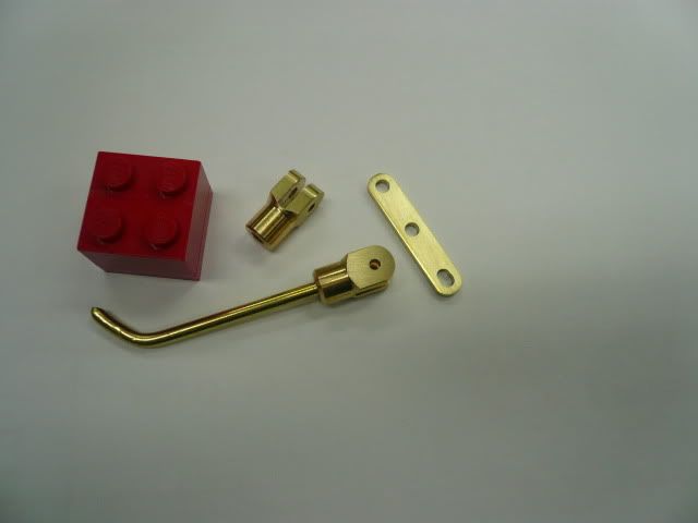
The eccentric eye is done the same way except the end is drilled 3/32” instead of being tapped. The bent rod in the photo is just a piece of scrap and not part of the engine.
P1050260.jpg


That’s it for today. Next up is the eccentric.

Dennis

P.S. I'm hitting "Post" without benefit of the inoperative "Preview" feature, so bear with me.
 
Denis,
I have the same problem....preview and ......wait and.....wait so I post and look.

But...Nice Parts...Project is coming along great

Tony
 
Back
Top