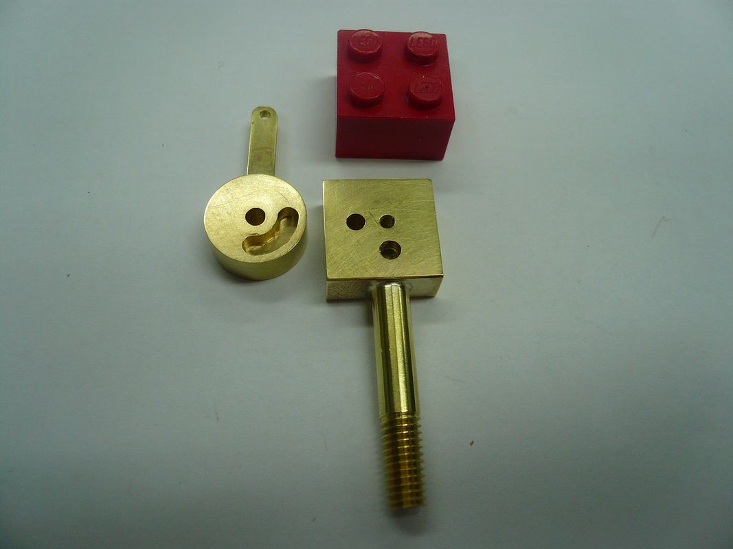
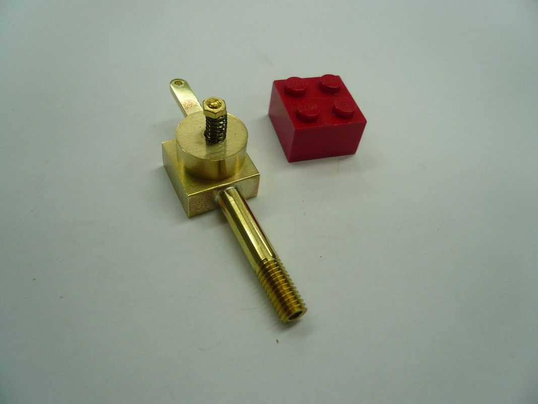
- Joined
- Feb 25, 2008
- Messages
- 464
- Reaction score
- 7
Thank you for the kind comments...they're appreciated.
cobra428....I've got an order in for some blue Dykem. I'm partial to the red because it hides the blood.
This must be the day for lubricators because Deanofid just posted his. Definitely worth looking at.
Here we go with mine:
Displacement Lubricator
The Displacement Lubricator is a device that supplies oil to the inner workings of the engine. It mounts on one side of the steam admission tee shown in my previous post.
Heres a schematic of a typical lubricator:
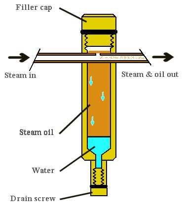
There is a good explanation of how these work on this SITE which is where I got the above photo. Rudys Lubricator is a slight variation in that his is mounted on the end of the steam pipe.
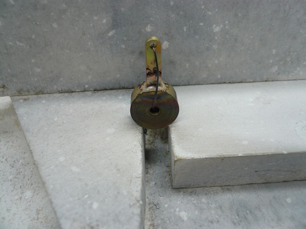
The body is made from a piece of 5/16 brass rod, drilled to form the oil chamber. I drilled with a #1 drill so I could tap the top 1/4-28 for the filler cap.
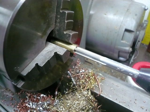
The bottom end is drilled 3/32 for the drain line and a 3/32 hole is drilled on the side for the steam line.
The filler cap was made as an assembly. I knurled, drilled and tapped a piece of 5/16 rod 1/4-28, parted it off and screwed it on a piece of 1/4-28 rod.
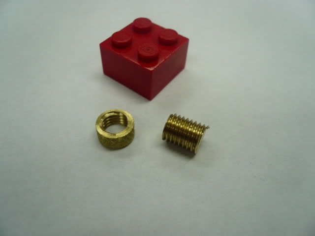
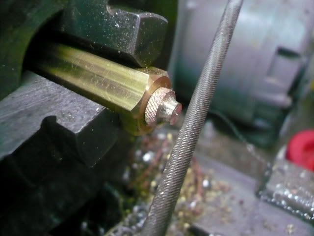
Silver soldered the two pieces, screwed the assembly into a threaded piece of hex and put a decorative shape on the top end using a chain saw file.
The steam pipe assembly starts with a 1/2 piece of 3/32 solid rod. The plans then call for this rod to be drilled through with a #72 drill. Thats 0.025. I figured theres no way I could do that so I first drilled it 3/8 deep with a 1/16 drill and then peck drilled the last 1/8 with the 0.025 drill.
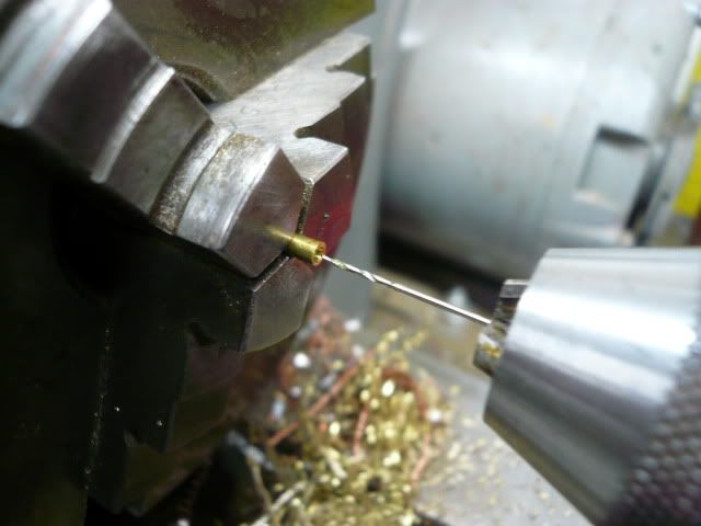
It worked and I didnt break the drill!! Rudy was insistent that the hole be no bigger than 0.025 to prevent flooding the engine with oil. However, Im hoping the length isn't critical (mine is 1/8" vs. his 1/2"). I guess Ill find out.
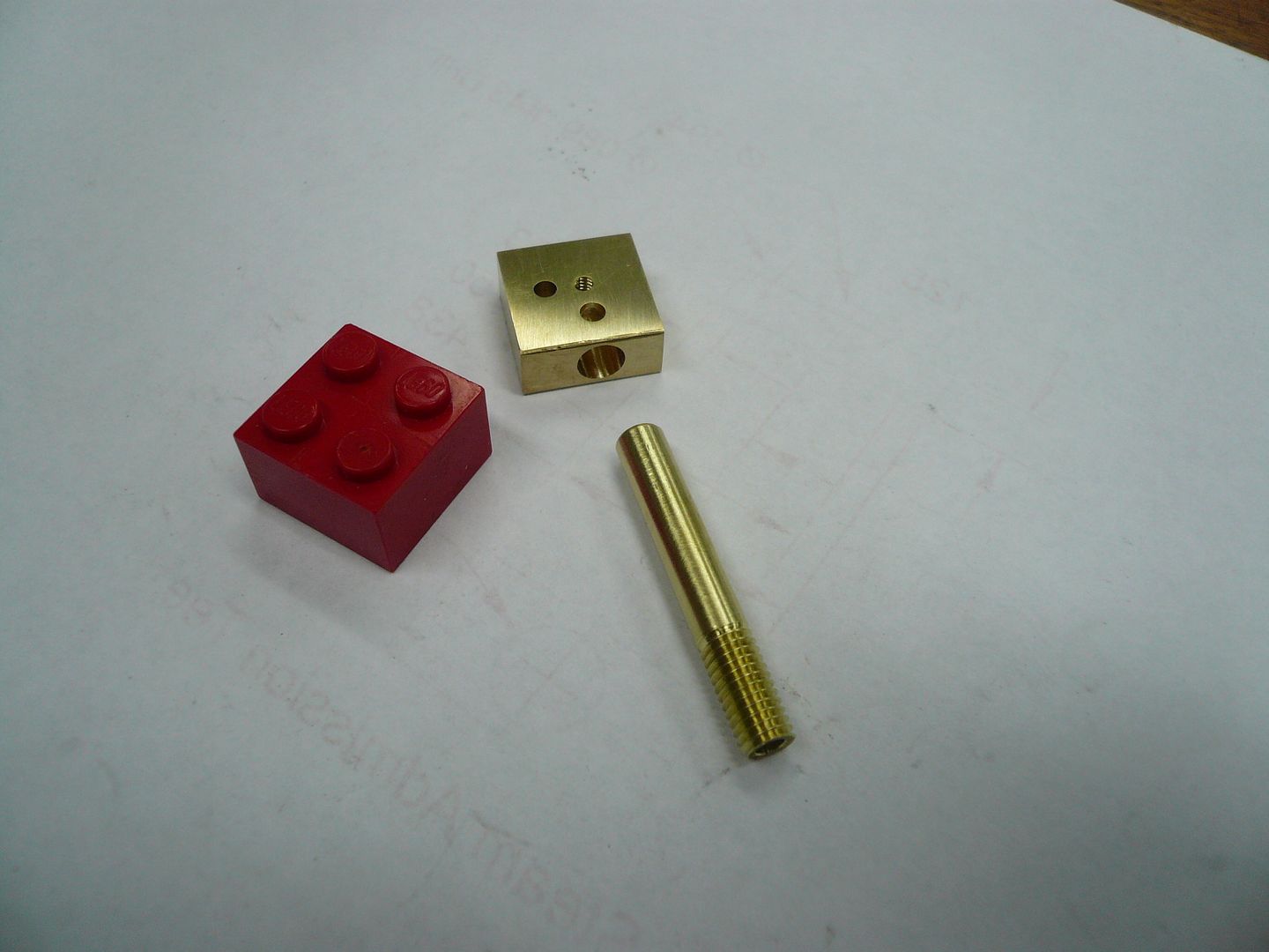
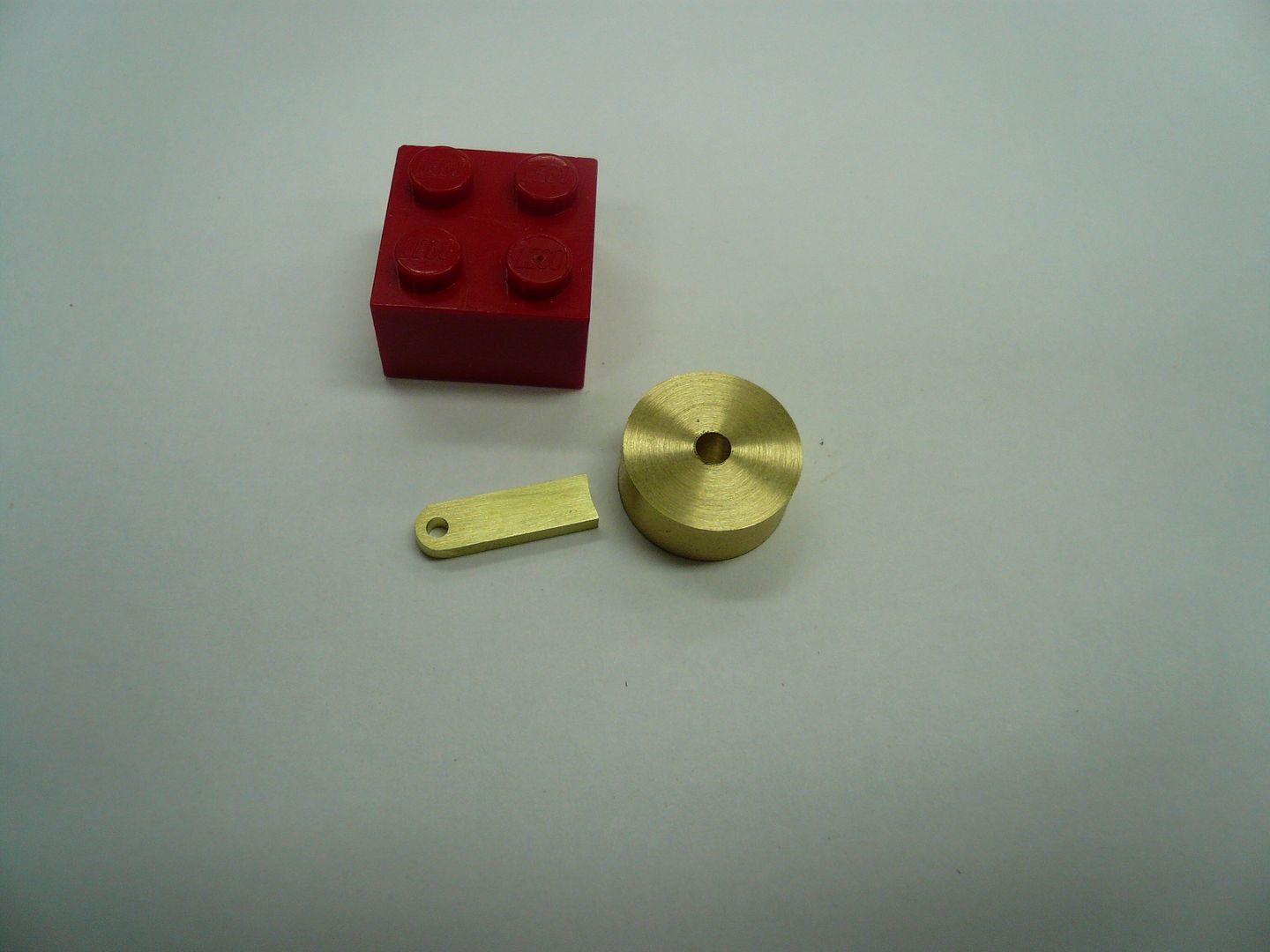
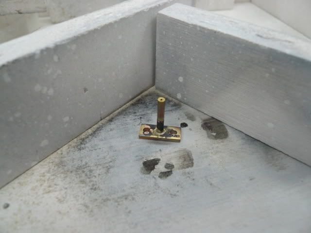
Next I made a bolting flange from 1/16 x 1/4 stock and silver soldered the steam pipe into it to complete the steam pipe sub-assembly.
The drain tube is made from 3/32 tubing and a piece of 1/4 rod. No pictures, but its pretty straight forward.
The drain plug is also an assembly. It starts with a piece of 4-40 threaded rod, pointed to form a needle valve.
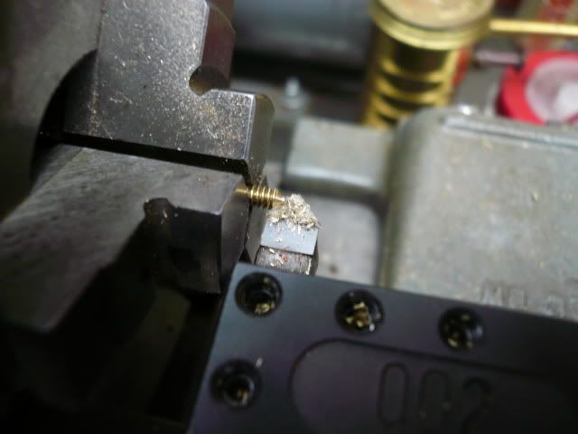
The handle part is made by knurling, tapping 4-40 and parting off a piece of 5/16 rod.
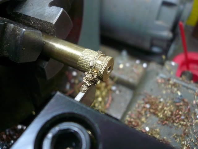
These two pieces are then screwed together and silver soldered. Then they're screwed into a piece of hex stock and faced smooth.
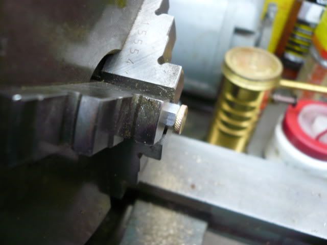
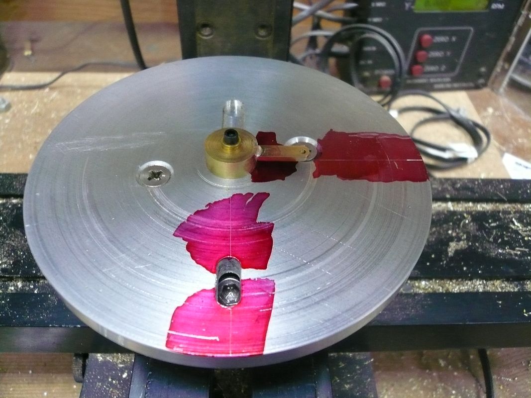
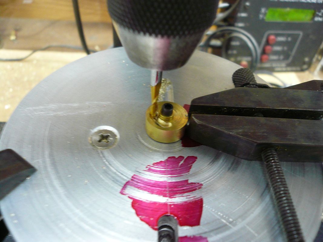
In lieu of a rotary table, I used the piece of hex stock to index the handle for decorative holes. I clamped a stop in the vise to keep the stock vertical, drilled a hole, rotated to the next flat and so on.
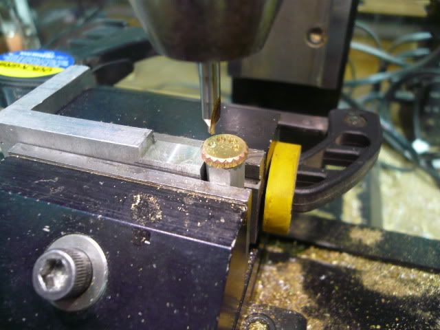
It worked out pretty well.
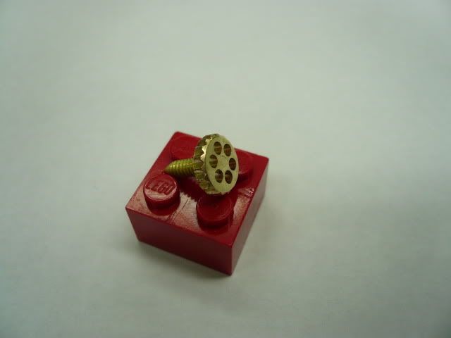
Youve probably noticed that the knurling pattern changes as you go through the photos. Thats cause I was experimenting. Knurling is still somewhat of a black art for me.
That completes the sub-assemblies.
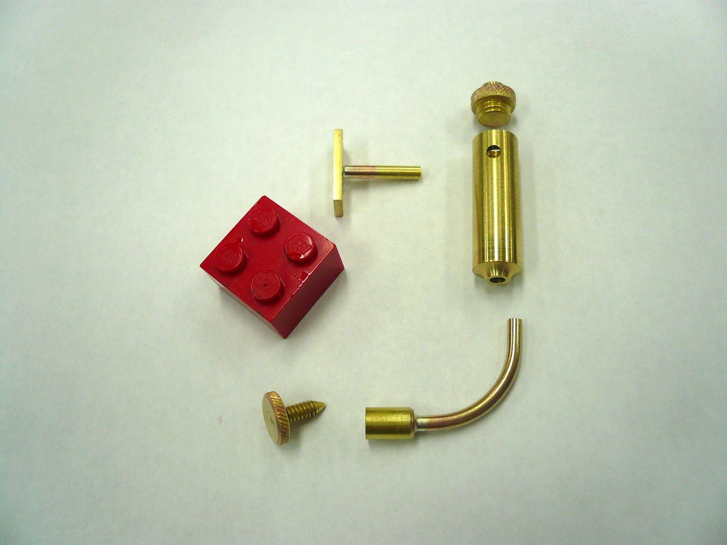
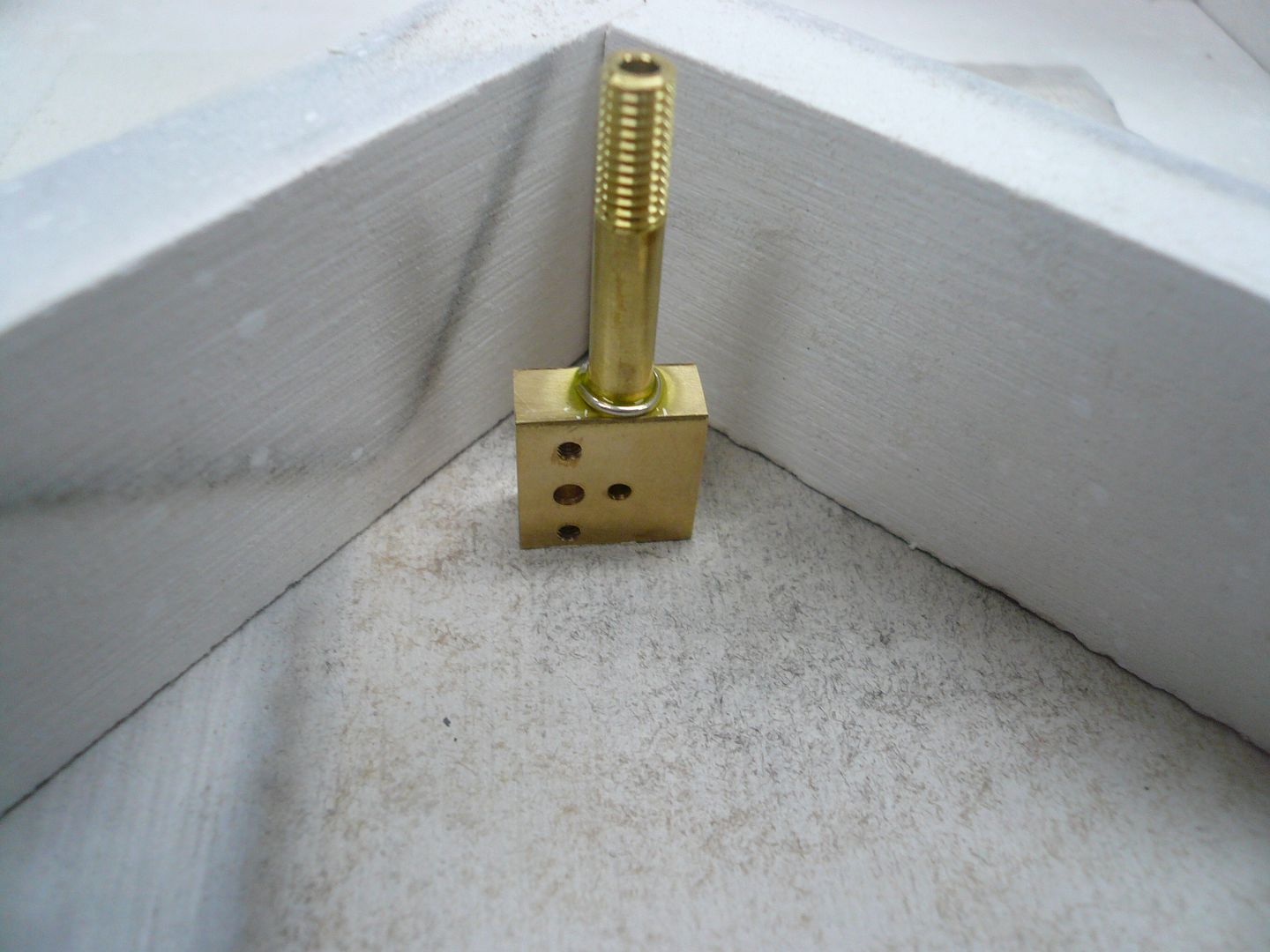
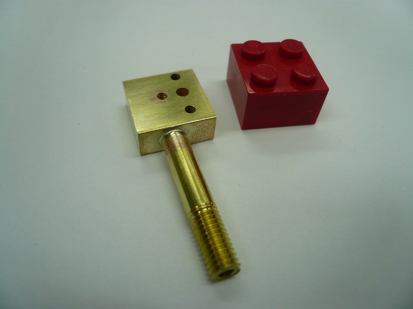
Next the sub-assemblies were silver soldered into the final assembly.
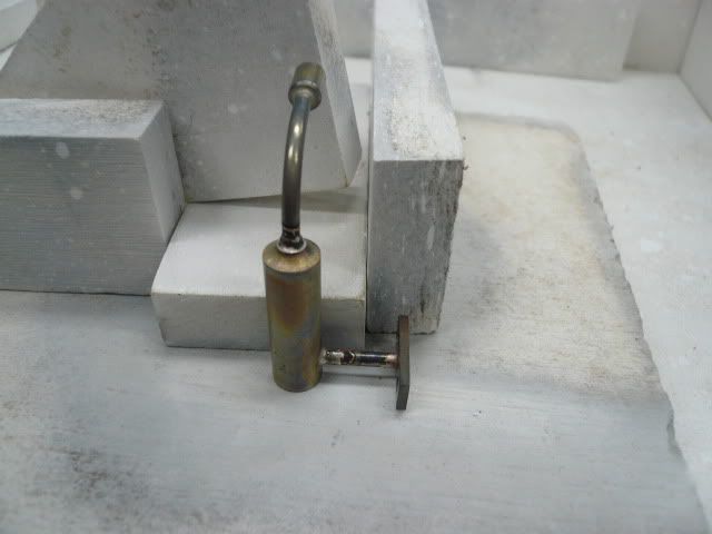
I kept the torch directed at the body and didnt have any problem with the sub-assemblies re-flowing. Whew!
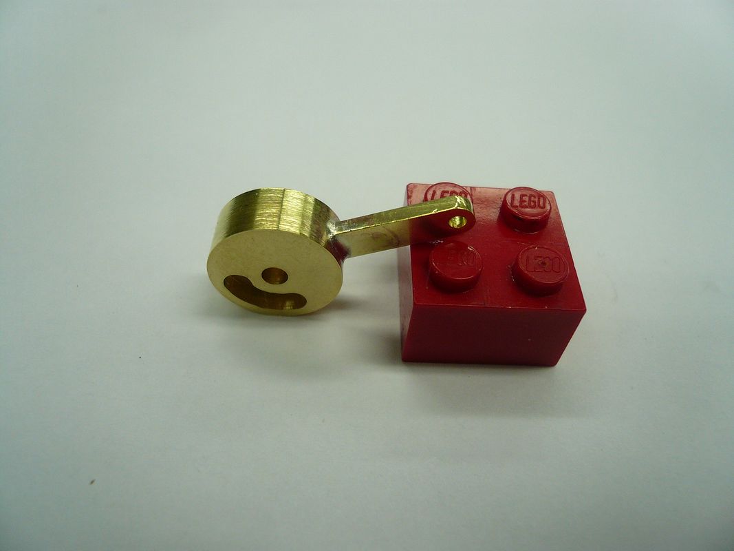
That completes the Displacement Lubricator
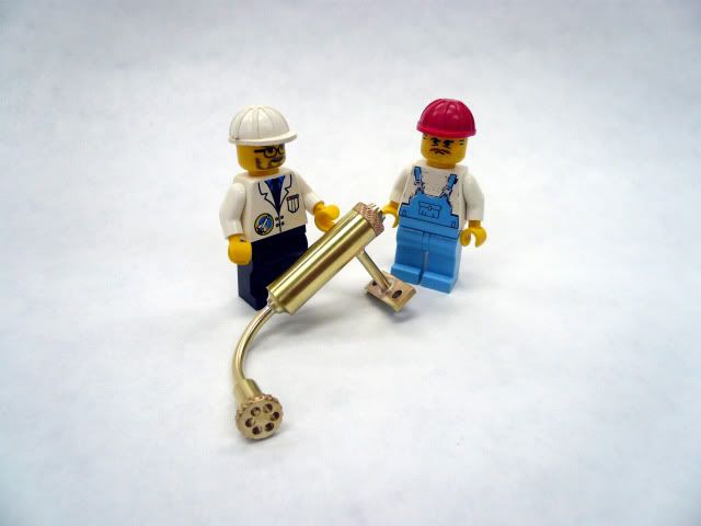
My grandsons called the NASA Inspector in on me. He didnt like the pinkish color on some of the brass, but bought off on it anyway.
Regards,
Dennis
cobra428....I've got an order in for some blue Dykem. I'm partial to the red because it hides the blood.
This must be the day for lubricators because Deanofid just posted his. Definitely worth looking at.
Here we go with mine:
Displacement Lubricator
The Displacement Lubricator is a device that supplies oil to the inner workings of the engine. It mounts on one side of the steam admission tee shown in my previous post.
Heres a schematic of a typical lubricator:

There is a good explanation of how these work on this SITE which is where I got the above photo. Rudys Lubricator is a slight variation in that his is mounted on the end of the steam pipe.
The body is made from a piece of 5/16 brass rod, drilled to form the oil chamber. I drilled with a #1 drill so I could tap the top 1/4-28 for the filler cap.

The bottom end is drilled 3/32 for the drain line and a 3/32 hole is drilled on the side for the steam line.
The filler cap was made as an assembly. I knurled, drilled and tapped a piece of 5/16 rod 1/4-28, parted it off and screwed it on a piece of 1/4-28 rod.

Silver soldered the two pieces, screwed the assembly into a threaded piece of hex and put a decorative shape on the top end using a chain saw file.

The steam pipe assembly starts with a 1/2 piece of 3/32 solid rod. The plans then call for this rod to be drilled through with a #72 drill. Thats 0.025. I figured theres no way I could do that so I first drilled it 3/8 deep with a 1/16 drill and then peck drilled the last 1/8 with the 0.025 drill.

It worked and I didnt break the drill!! Rudy was insistent that the hole be no bigger than 0.025 to prevent flooding the engine with oil. However, Im hoping the length isn't critical (mine is 1/8" vs. his 1/2"). I guess Ill find out.
Next I made a bolting flange from 1/16 x 1/4 stock and silver soldered the steam pipe into it to complete the steam pipe sub-assembly.

The drain tube is made from 3/32 tubing and a piece of 1/4 rod. No pictures, but its pretty straight forward.
The drain plug is also an assembly. It starts with a piece of 4-40 threaded rod, pointed to form a needle valve.

The handle part is made by knurling, tapping 4-40 and parting off a piece of 5/16 rod.

These two pieces are then screwed together and silver soldered. Then they're screwed into a piece of hex stock and faced smooth.

In lieu of a rotary table, I used the piece of hex stock to index the handle for decorative holes. I clamped a stop in the vise to keep the stock vertical, drilled a hole, rotated to the next flat and so on.

It worked out pretty well.

Youve probably noticed that the knurling pattern changes as you go through the photos. Thats cause I was experimenting. Knurling is still somewhat of a black art for me.
That completes the sub-assemblies.

Next the sub-assemblies were silver soldered into the final assembly.

I kept the torch directed at the body and didnt have any problem with the sub-assemblies re-flowing. Whew!
That completes the Displacement Lubricator

My grandsons called the NASA Inspector in on me. He didnt like the pinkish color on some of the brass, but bought off on it anyway.
Regards,
Dennis


![MeshMagic 3D Free 3D Modeling Software [Download]](https://m.media-amazon.com/images/I/B1U+p8ewjGS._SL500_.png)


![DreamPlan Home Design and Landscaping Software Free for Windows [PC Download]](https://m.media-amazon.com/images/I/51kvZH2dVLL._SL500_.jpg)


