Building of TINY INLINE 4 in Brazil

Home Model Engine Machinist Forum

Help Support Home Model Engine Machinist Forum:

This site may earn a commission from merchant affiliate links, including eBay, Amazon, and others.
Hey edi!
Thanks for the reply.
I see you used a #8 cutter...DId you make the offset cuts with that cutter as well, or finish the gears by hand.
My calculations tell me I should use a number 7 cutter to account for the offset moves...
I appreciate your input.
Thanks.
 
Hey edi!
Thanks for the reply.
I see you used a #8 cutter...DId you make the offset cuts with that cutter as well, or finish the gears by hand.
My calculations tell me I should use a number 7 cutter to account for the offset moves...
I appreciate your input.
Thanks.

that`s OK Greg. My pleasure!
No I did not make the offset cut, I plan to rework the gears to machine the offset and correct the teeth profile.

Edi
 
Hi Edi,
Good to meet you and really appreciate all the pictures,I will watch your progress with much interest.
Allen.
 
ello to all!
I'm back to the shop to finish the Tiny 4 In Line (Kelly Design).
I need to rework the distributor bevel gears because the teeth profile is not correct. The teeth head is not parallel. I did not correct the profile.

The gears are 12 teeth 48 DP 1:1 ratio

See picture bellow
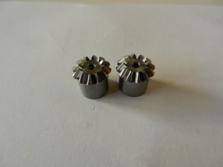

I will now follow Gail instructions bellow
Now with Dan's easy graphical solution there is only one number left that will be needed to to machine the gear. That will be a constant for any given diametrical pitch (DP) and is Pi/(4*DP). In your case using 48 DP cutters it is Pi/(4*48= Pi/192 = 0.0164

This is the vertical distance that you have to move the cutter off of the center line of the blank to make the cutter pass through the same point on the pitch circle when the gear blank is rotated 1/4 tooth.

To machine the gear, put the blank on an arbor and the cutter on the center line of the arbor. Cut all the teeth indexing a full tooth. In the case of a 40 tooth gear this will be 360/40 = 9 degrees.

Next index the gear 1/4 of a tooth. In the 40 tooth gear this will be 9/4 =2.25 degrees. Now move the cutter vertically the amount calculated above so that it will pass through the same gash at the small end of the bevel. You will have to raise or lower the cutter depending on which way you indexed the 2.25 degrees. Go all the way around the gear again in full tooth increments. Now take out the 2.25 degrees to get back to center line and go an additional 2.25 degrees. Now move the cutter so it again passes through the same spot on the pitch cirlcle. If you raised it before, lower it twice the above calculated value and you should be there. Onc more around in full tooth increments and you are done.


A few notes.
Use the same cutter number that you would use if cutting a spur gear with the same number of teeth.

Try to arrange the work so the cutter is pushing the blank onto your mandrel. Dedending on your index head it is sometimes easier to put the cutter on reversed and run the mill in reverse in order to get the index head crank in a easier position to operate. You will be turning it a lot.

If your are just playing, I suggest that you cut a 1:1 set of 18 tooth gears to get the feel for it. This makes all the indexing angles even numbers and a multiple of 5 degrees. You can even do this with a spindex. The 1:1 ratio makes the blank angles 45 degrees which is easy to set up on the lathe.
___________
Gail in New Mexico, USA

HERE IS MY DOUBT AND NEED HELP.
WHAT IS THE ANGLE I SHOULD SET THE DIVIDING HEAD? WOULD IT BE 45 DEGREES THE SAME AS THE BLANK HEAD? AS GAIL DID NOT SAY ABOUT THAT I'M ASSUMING IT IS THE SAME.
Some literature says that the angle of the valey is different from the top.

Thanks in advance for your kind help.

Edi
 
Hi CS!
Thanks for your help. I think I will need a cuple new blanks and start it over.

Di you finished your Tiny 4?

Edi
Hi again Edi
Yes I have finished the Tiny. And had it running. But the piston o-rings wear out so it has been sitting on the shelv for long time.
One day in the future I will make new pistons in cast iron steel that are lapped to the cylinders.
CS
 
Hi again Edi.
Yes I have finnished the Tiny, and had it running. The O-rings on the pistons is now weard out so I have to tear it down to fit new ones. Or I make new pistons out of cast iron. This piston will be lapped to the cylinders to avoid using pistonrings
CS
 
Hi all!
This is a test on posting pictures.
Thanks for you advise Cogsy! I think it worked!!!

20141104_161644.jpg
 
Hi to all!
As you may know I screwed on making the distributor gears. I tried to rework them to correct the profile of the teeth but it did not work.
I decided to make new ones.

Last photo is a test of the program. I tried to post a video of the gear being machined on CNC rotary table but, I was not able.
As you can see the teeth are now correct.

IMG_20180325_113537628.jpg


IMG_20180325_114902958.jpg


IMG_20180324_184717457.jpg
 
Next I lapped the liners. As don’t have a honing tool, I decided to make a test grinding it on the lathe. For that I installed a router spindle on the cross slide of the lathe. It really worked well.
[/ATTACH][/ATTACH][/ATTACH]

I then changed the grid of the grinding bit for final finishing
[/ATTACH]
 

Attachments

  • DSCN2762.jpg
    DSCN2762.jpg
    83 KB
  • DSCN2774.jpg
    DSCN2774.jpg
    87.4 KB
  • DSCN2775.jpg
    DSCN2775.jpg
    120.9 KB
  • DSCN2761.jpg
    DSCN2761.jpg
    106.8 KB
  • DSCN2760.jpg
    DSCN2760.jpg
    122.6 KB
  • DSCN2755.jpg
    DSCN2755.jpg
    145.3 KB
Great to see you back at it Edi. I think you've been building your Tiny almost as long as I've been building my Peewee. I'm happy to not be the only one who takes a while to get these things finished!
 
Thanks Cogsy!
I had some personal issues that made me to be away from my engine project. I'm now very motivated to finish this project and start on the PeeWee (I also have the kit). I'm following your building with very close interest.

The little Tiny Inline Four is almost ready to test if it runs. Only needing some fine adjustments on some moving parts.
I already tested the distributor gears assembled on the block and distributor body and it is working fine.

Today I will post some more photos.


Edi
 
Hi Guys!
Here are samo more photos of my progress.
Had the Liners installed and leveled them to the block. I have used Loctite to fix it to the block.
DSCN2848.jpg
DSCN2851.jpg

Tested the Gears on the distributor Body and Camshaft. Worked really fine moving freely
DSCN2865.jpg

I also finished the Spark Plugs and tested it on the cooker ligher spark (my wife cooker Hahahaha)
DSCN2876.jpg

Here is a test of the valve spring clip
DSCN2875.jpg

I would like your opinion/recommendation on the Crankshaft.
Should I machine the counter balances or should leave as it is?
DSCN2852.jpg
DSCN2853.jpg
DSCN2854.jpg

That is it for today.

Edi
 
Hi Edi , Please keep the photos coming,excellent work.
Cheers
Allen
 
I don't know how much difference it really makes for balance, but I personally like the look of machined counterweights better than round ones. However, realistically no-one will see it when it's assembled and of course there's always a risk of making an error while machining and possibly messing up what you've already done. So it's really your choice. It's all looking really nice!
 

Latest posts

Back
Top