Building Elmer's Fancy

Home Model Engine Machinist Forum

Help Support Home Model Engine Machinist Forum:

This site may earn a commission from merchant affiliate links, including eBay, Amazon, and others.
CC, Rob: many thanks - I really appreciate your input.

CC:
gives us something to aim at
- Thank you; I feel honoured, but there are a LOT of other members of HMEM who gives a better target to aim at; I'm still trying to aim there :)

Rob:
did you forge over the end of the silver steel first , then grind it to shape ?
Uhm, no... :hDe: Uhm... I cheated :-[
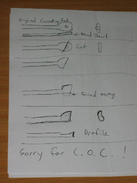
On my other build (my "first" engine - that is now rapidly moving down the line :-[ ), I made a "wrong" connecting rod from silver steel (the flats on the head were not parallel to the shaft).
Cheap miser that I am, instead of throwing it away, I cut off the head through the hole, then ground the profile as needed from what was left, and then hardened it. I didn't bother to temper it again, just slipped it over the oilstone a couple of times to get some nice cutting surfaces. For brass and aluminium, that should be OK, but if I need to do steel or interrupted cuts with it, I'll have to temper it a bit...

Crap-O-Cad attached of turning a con rod into a boring bar - might be useful for someone , but you will have to turn your head a bit (sorry) :)

si1176.jpg


Regards, Arnold
[Edit: turned the picture right way around]
 
Hi Arnold . Thanks for the description and a stiff neck ;D ,.......... there is nothing wrong with a bit of recycling ,i have a pile of bits ready for modification.

Regards Rob
 
Pleasure Rob; Apologies for the stiff neck though ;)
Regards, Arnold
 
Had some more fun today...

First turned the 3mm pivot shaft from the only piece of 6mm brass rod I have & threaded the end M3. Took a photo of that but it's so out of focus I can't show it here :hDe:

Elmer suggests an aluminium "plug" in the cylinder bore when you solder the pivot pin to the block to prevent solder from flowing into the cylinder. He also suggests putting some packing over the cylinder bore opening when machining the recesses on the block face. I combined these requirements (and a "no burrs left in the cylinder option ;) ) by taking the piece of aluminium off-cut that was left when I made the column - it had about a 6mm length on it that was machined the same size as the column's head; the rest was thicker, but just long enough to use . I just chucked it on the thinner machined section, and turned down the rest to fit fairly tightly into the bore. In fact, when I tested it, the fit was so close, that I couldn't push the cylinder much more than 5 mm over it; it would just pop right off again from air pressure in the cylinder.

Not wanting to struggle to get it out later because of an air-lock, I drilled a 5mm hole through the plug; if needed I can then use it as a mandrel and/or lap later in the build :)

Then I set up the cylinder block (with the aluminium plug pressed in) in the 4-jaw and centered on the pivot hole. Elmer mentions that you must use a dial test indicator to check the squareness. I don't have a DTI yet, so used my favorite dial indicator. I know my lathe faces slightly concave, so rather than tramming like Elmer suggests, I just took alternative readings on the ends by rotating the chuck and used the chuck spanner's handle as a lever between the brass plug and chuck face to get things squared. Then a test on a "circle" closer to the pivot hole with the dial indicator showed no discernible run-out; meaning the cylinder face was square on all sides.

By now, you should be tired of reading, so here's a picture of how I did the set-up to turn the recesses and pivot hole:
smaller-IMG_1178.JPG


Easy going; turned the recesses to 0.4mm deep and drilled the pivot shaft's hole. With the aluminium plug inside, I drilled the 3mm pivot hole just till the first aluminium swarf came out, so the hole is not entirely through the brass - leaving some retaining shoulders and no burrs in the cylinder. Then to make life easier while soldering, I put a generous fillet in the hole using a countersink.

I turned the aluminium plug in the cylinder to get away from the "dent" left by the drill. Got everything right for soldering - all cleaned up etc.
Then the FUN started :fan: - the pivot shaft was WAY to loose in it's hole :wall: - I measured, thought, reflected, and then looked at my drill set; I drilled the darn pivot hole 3.5mm and not 3mm !!! :rant:.

After a cup of coffee I decided next best was to make a new pivot shaft; just turn it 3.5mm for the section that goes into the cylinder block and 3mm for the rest. Problem was, I didn't have brass stock left for it. OK, some 6mm silver steel turned down should do the job. Turned a new shaft; used emery to get the 3mm section bang on size for the column, and then proceeded to turn the 3.5mm section under-size again! :rant: :rant:

Well, third-time lucky ??? Made a soap advertisement pivot shaft (of the New! Improved! variety) - it worked! - was still slightly loose in the hole - ideal for soldering. Not wanting to struggle with it moving when soldering, I used the rough beaks on my big vice to put some raises & dents on the 3.5mm section - worked a charm; I needed to lightly tap the shaft into place, it didn't wiggle a bit in the hole and was nice and square in all directions, leaving nice room for the solder to wick in :) (If this seems like a cheat - yes it is, but it beats the heck out of trying to get punch marks on the shaft to get it to stay put ;D)

So ended off this evening with this:
smaller-IMG_1179.JPG

2 shafts now useless for this build - for the photo wall-of-shame; they will be re-used ;), the aluminium "multi-purpose" bit with the dent left by drilling, and the cylinder block with shaft eventually attached.

At least little Fancy's column and cylinder block could come together - some bling still needed though :):
smaller-IMG_1182.JPG


Regards, Arnold
 
arnoldb said:
After a cup of coffee I decided next best was to make a new pivot shaft ......................... and then proceeded to turn the 3.5mm section under-size again! :rant: :rant:

Don't fret Arnold ................. I think we all have that same Tee Shirt if we're honest ;D ............. thanks for sharing 8) .... you recovered so that's good .... and, can I say, it's a very enjoyable thread ;)

CC
 
Great photo build Arnold , looks like you will have it up and running in no time Thm:
Regards Rob
 
Thanks CC & Rob :)

CrewCab said:
Don't fret Arnold ................. I think we all have that same Tee Shirt if we're honest ;D ...........
Thanks CC - Darn - thought I had a unique Tee Shirt - didn't know it was in fashion :big: Rof} .

RobWilson said:
Great photo build Arnold , looks like you will have it up and running in no time Thm:
Regards Rob
Thanks Rob - I need to improve a lot of my skills though... Machining definitely, and as it turns out, Photography as well!! ;D

Kind Regards, Arnold
 
RobWilson said:
Great photo build Arnold , looks like you will have it up and running in no time Thm:
Regards Rob

Ditto. :bow:

Best Regards
Bob
 
Hi , Arnold , your machining gets the Thm: from me ,looks like your doing a real fine job of the engine, still have stiff neck from crap o cad photo . ;D
Regards Rob
 
Maryak said:
Ditto. :bow:

Best Regards
Bob
Thank you very much Bob - I'm just trying to learn & apply from you and the other members !! :)

RobWilson said:
Hi , Arnold , your machining gets the Thm: from me ,looks like your doing a real fine job of the engine, still have stiff neck from crap o cad photo . ;D
Regards Rob
Uhm.... scratch.gif Shucks... scratch.gif ... Rob, thank you very much for the comment on my machining. How can I help with the stiff neck? - I'll try not to put a foot photo wrong again !

Kind Regards, Arnold
 
Coming together nice Arnold

Good write up thanks for sharing.

Stew
 
SBWHART said:
Coming together nice Arnold

Good write up thanks for sharing.

Stew
Thanks very much Stew
Regards, Arnold
 
The quest continues...

Having gone to bed last night not having any 6mm brass rod left (too little anyway) I woke this morning with an idea :idea:
Once again, it's cheating (I know) :hDe:, but I didn't want to turn a length of 12 mm brass down to mostly 3mm for the con rod.
My idea was to use some 3.2mm "brass" brazing rod that I have, and solder the 6mm piece on for the big-end link:
smaller-IMG_1184.JPG


So I turned a bit of the brazing rod down to 3mm, drilled a 3mm hole in the piece of 6mm rod, and soldered them together. At least my silver soldering is improving; in fact I'm actually starting to like it - still not pretty, but improving:
smaller-IMG_1186.JPG


I then showed some grit, and proceeded to clean up the "con-rod in making" with a bit of filing and a lot of emery & oil.
Looking at the plans, I saw that I had forgotten to cut the threads on the piston end - scratch.gif - Easy, just chuck it up with the lump that has to become the big end in the space behind the chuck jaws and thread it, right ? :noidea: - No Go! - it's too short! :wall:

So, turned a "collet" out of 6mm drill rod: Could only find a broken 3.2 mm drill :rant: - so used my M4 tap drill (3.3mm) to drill a hole through. Then with the dremel, cut 2 grooves part-way on the length, and one slot all the way through the center. Chucked the con rod in this in the 3-jaw; worked a treat to turn down from 3.2mm to 3mm & thread the piston end. Sorry- forgot to take a photo....

Before setting up the vertical slide for milling, I first turned the piston - got it bang on size by just turning:
smaller-IMG_1188.JPG
.

Turned some odd-spaced :hDe: oil grooves on the piston. Then center drilled, drilled 2.5mm to a bit past part-off point and then bored (well... "drilled") the piston inside to depth. Then with 3mm tap in the tailstock drill, just tapped the 3mm thread in the top of the piston:
smaller-IMG_1189.JPG

To get a better feel for the tapping, I just set the Myford up as if I want to use back-gear, then leave the back-gear selector in high speed setting. With this set-up, the chuck is very loose to turn by hand and gives nice "feel" for threading.

Parted off the piston - a piece of 1.6mm brazing rod in the tailstock chuck prevented it from going in the swarf-heap:
smaller-IMG_1191.JPG
.

Then I set up the vertical slide, and using the collet I made earlier to grip the con rod, I milled one flat face on the big end, marked it out, center drilled, and drilled and reamed a 2mm hole through it. With a piece of 2mm piano wire in the jaws of the tailstock chuck (now inserted in the headstock ;) ) I just removed the con rod (collet and all) from the milling vice, turned it 180 deg, and shoved it over the piano wire in the chuck. Then I brought the carriage with the vertical slide back, and just clamped the collet up again - this way everything stays in alignment, and the next face on the big end is nice ans parallel with the original. - Once again, I forgot to take a photo!

This is where I ended for tonight: A piston and con rod:
smaller-IMG_1193.JPG


And screwed together:
smaller-IMG_1195.JPG


Initially and intentionally, I left the thread on the connecting rod slightly short - I needed to add a couple more threads to the con rod, but got pretty close. Elmer's plans calls for this entire assembly to be 1 1/2" long, and my calipers shows overall length when screwed together 1.4995" - should be close enough ;)

Darn - wish it was weekend again...
Regards, Arnold
 
Good, steady progress. You'll get there before you know it.
 
arnoldb said:
The quest continues...

Having gone to bed last night not having any 6mm brass rod left (too little anyway) I woke this morning with an idea

Regards, Arnold

Thats when I go back to sleep . . .

Looking good, I need a nap after reading what you went through to get the con rod built

Robert
 
Thanks rleete & Robert :)
Foozer said:
Thats when I go back to sleep . . .
I keep forgetting the time zones across the globe... :big:

Foozer said:
Looking good, I need a nap after reading what you went through to get the con rod built
??? - The thought of making all that lot, or just boring ? :big: - Now it's beddy-bye time for me.

Regards, Arnold
 
Foozer said:
"Necessity, who is the mother of invention" - Plato

She works hard does she not

Not boring at all :)

Robert

;D - poor old mum; rarely gets a break :) - Thanks Robert!

Gave her a break for a change today - came home all cranky from work, and decided some stress could be turned into chips; nothing spectacular; just _something_ for a change.

As I was already feeling "cranky" - I decided to leave the Fancy's crank for later.

Earlier this week I found some substitute "loctite" suitable for retaining bearings & bushes, so just did a simple turning job - made the main bearing bush. A simple job - turn-drill-ream&part , but oh-so-relaxing (and it beats ironing shirts / washing floors :big: )
Pressed it into place in the column with some of the retaining compound so it can set.
Drilled the port hole in the cylinder block & cleaned up the burrs, then put the spares together to get an idea what I let myself in for:
smaller-IMG_1197.JPG

The "ugly" hole at the top of the column is where I'll press in the steam pipe.

Still lots to do: crankshaft, flywheel, base (I bet Fancy's getting tired of lying down ;) ), some "bling" & a coat of varnish to protect the bling, and yes, a nicer nut on the pivot shaft ;)

Regards, Arnold
 
Looking very good Arnold :bow: Thm: looks like it will be running in no time
Regards Rob
 
Arnold,

Nice work :bow: As Rob says not long now before a runner. ;D

Best Regards
Bob
 

Latest posts

Back
Top