Building a twin cylinder inline i.c. engine.

Home Model Engine Machinist Forum

Help Support Home Model Engine Machinist Forum:

This site may earn a commission from merchant affiliate links, including eBay, Amazon, and others.
There is another reason for using an iron liner in an alloy cylinder - that is the thermal properties of the alloy, which conducts heat significantly better than iron.
This may not matter if you only intend to run the engine for relatively short periods and without load.
If you are happy with one piece iron cylinders, it is quite simple to add the raised lip feature for sealing to the head gasket.
Here's hoping it all goes well for you, Brian!
Why not cast the block in Alusil?
 
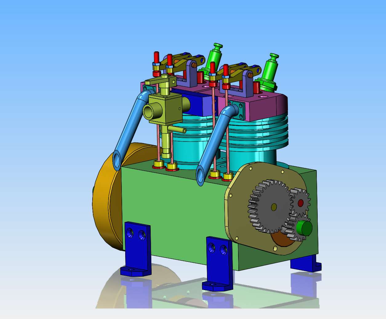
We got gears, we a got a carburetor, and we got an exhaust system. There is a guard for fitting over the gears as well, but I left it off so the gears show.--Almost finished modelling!!
0V5BcK.jpg
 
If you make the heads out of cast iron also, you could machine a short taper on the top of the cylinder. A matching taper on the mating face of the head, then lap the two together, no gasket, seperate valve guides or seats needed either? I had a Velocette 500cc MSS in the late 60’s which had this arrangement.
 
Last edited:
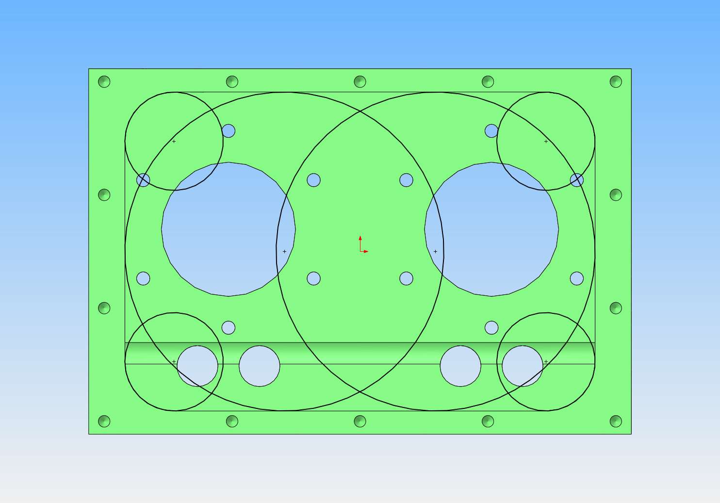
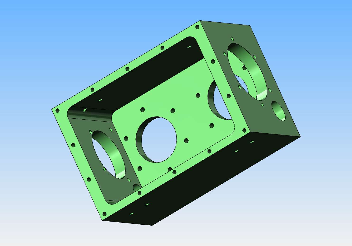
The redesign of this engine is mostly finished. It has a 1" bore and ended up with a 0.944" stroke. The three worst parts to machine will be the crankcase, the crankshaft, and the cams. I think I will machine the crankcase first. The crankcase looks huge, but in reality it's a bit less than 3" square and 4 1/8" long. The hard part is going to be the large cavity in the crankcase which is 2 1/8" deep, and is "blind" meaning it doesn't go all the way through. The radius in the corners is 3/16", so first step will be to drill the four corners with a 3/8" drill to full depth and then finish up with an endmill to get a flat bottom. Then mount it on the lathe faceplate and do a couple of overlapping 2.43" diameter blind bores to hog out the rest of the material. This will still leave some material to be removed from the corners that can probably be cleaned out on the milling machine. I think this is the best approach with a home shop/ manual mill and lathe. if anyone thinks of something better, please let me know.
sSpK5K.jpg
 
The redesign of this engine is mostly finished. It has a 1" bore and ended up with a 0.944" stroke. The three worst parts to machine will be the crankcase, the crankshaft, and the cams. I think I will machine the crankcase first. The crankcase looks huge, but in reality it's a bit less than 3" square and 4 1/8" long. The hard part is going to be the large cavity in the crankcase which is 2 1/8" deep, and is "blind" meaning it doesn't go all the way through. The radius in the corners is 3/16", so first step will be to drill the four corners with a 3/8" drill to full depth and then finish up with an endmill to get a flat bottom. Then mount it on the lathe faceplate and do a couple of overlapping 2.43" diameter blind bores to hog out the rest of the material. This will still leave some material to be removed from the corners that can probably be cleaned out on the milling machine. I think this is the best approach with a home shop/ manual mill and lathe. if anyone thinks of something better, please let me know.
sSpK5K.jpg
Hi,

I don't know much about machining but making the crankcase by fabrication will be much cheaper and faster than machining it out of solid block of metal.
I mean using flat bars and bolting it all together.
Not aesthetically pleasing but it may do the job.

regards
Nikhil
 
Making from solid should keep everything lined up provided you position the holes accurately to start with. Bolting up from plate can introduce errors if pieces are not perfectly true and square, clearance holes allow plates to move slightly etc. Also less joints for crankcase oil to leak out of.

Boring on lathe then milling the rest with a long series cutter worked for me on the opposed twin version. 4-jaw will be simpler than using the faceplate.
 

Attachments

  • IMAG2695.jpg
    IMAG2695.jpg
    790.8 KB
Last edited:
Hi Brian, Whether drilled and milled, or lathe bored and milled, you'll get it right, because you do.
Personally, as there are solders available now for aluminium, that I have used to make small "tanks/boxes", I would buy some 1/4inch aluminium plate (or whatever) and solder-up the crankcase. The solders are a high % aluminium, do not need red heat (that would melt the aluminium!) so are strong, and with good assembly jigs I am sure you could make the casing from panels, then finish machine all the registration faces, bores, etc.
Just an option... But I know you love making swarf!
K2
 
You can put the camshaft wherever you like if you introduce an idler gear. This was E T Westbury's usual arrangement. It also allows smaller gears to be used which improves the appearance of the timing case. Big gears are not nessary to drive the camshaft.
 
Look at the images, there is an idler as per the original design.
 
I can go to a 0.375" rad in the corners without fouling any moving parts inside the crankcase. This would mean a drilled 3/4" hole in each of the four corners on the mill and two very large bores on the lathe while held in the four jaw chuck.
Fc8SZ9.jpg
 
Last edited:
I just talked to my metal supplier, and a piece of aluminum 3" square x 4 1/4" long will cost me $26.00. I think I'm going to buy it and risk machining this from solid. Nothing ventured, nothing gained.
 
Brian, Will you Bore the larger holes first? Then one setting on the Mill should complete the corners, flat sides, etc. And the larger cut of the large bores is unbroken... for the first hole anyway. Intermittent cutting with the miller, on smaller tools, which was going to happen anyway. (I'm here to learn, so if my method is wrong I'll be glad to hear, and why!).
That is a lot of swarf! Have fun!
K2
 

Latest posts

Back
Top