- Joined
- Dec 28, 2008
- Messages
- 1,731
- Reaction score
- 9
#60 For today's post I'll start by making the 'rocker bearing'. The fist step was to mill an accurate block of brass, and check it for squareness.

#61 I used a 'tenths' indicator to center it in the small four jaw for drilling and reaming the 'rocker shaft' hole. In this setup I also turned the 3/16" x 7/32" cylindrical boss on the one side shown in the drawing.

#62 To mill out the 1/4" x 3/8" opening took an unsettling set up that required the use of space blocks on the opposite end of the vise to balance out jaw pressure. It would have made a much better set up to have had an additional 1/8" added to the 7/16" dimension. It would be milled off after the opening was milled out by simply flipping it over. Live and learn. :")

#63 Below is the finished 'rocker bearing'. The holes are clearance drilled for 4-40 studs. I won't be using the 3-48 specified in the plans due to not having the right size material to thread or the 3-48 nuts on hand. We do what we do out of necessity.

#64 The two piece 'crosshead guides' are next. After drilling the eight 4-40 clearance holes, I took the previously milled pieces and filed off the machine marks left by the end milling.

#65 In the plans Elmer suggests three cosmetic options that can be used on these pieces. Leave them plain, drill 5 spaced holes, or mill out an arch. Unfortunately there are no details like the dimensions, drill size, spacing etc.
I calculated for an 'arch' milled from the top down with the piece up side down in the vise. The machine moves are; one cut with a 1/4" ball end mill set to a depth half the height of the work piece using the "Y" axis (hope I got this right). Zero out on the end and move in along the "X" axis .350" for the first cut, and 1.710" for the second cut using the "Y" table movement. Switch to a regular square 1/4" end mill, set to the same depth and cut with one pass at.475" and 1.585" using the "Y" table movement. Finish up by cleaning out the remaining material between the last two cuts. This of course is my idea of the arch, you could shorten it a bit by adding 10 or 20 thousands to the first move on both end mill, and at the same time subtracting the same amount from the second movement of both end mills. This worked well, but I decided on using the drilled hole option on this build instead.
I decided to try five equally spaced 1/4" reamed holes. The work pieces were stacked laying on their sides in the mills vise. Why do all of this twice. After zeroing out on the outer edge, the table was moved along the "X" axis to .350", .690", 1.030", 1.370", and 1.710". At each location I center drilled, drilled, and reamed before moving to the next stop (location).

#66 After d-burring the holes by hand using a countersink, a light sanding with 600 grit sand paper,the parts are finished.

#67 The rest of this post is about how I made the 'connecting rod'. I feel proud of the new method I used today to create its tapered portion. On an rectangle of brass I laid out all the dimensions for tuning, and the locations of the 3/16" hole for the 'crank screw', and the 1/16" hole for the 'piston rod' pivot pin. After drilling and reaming the holes I centered it in the for jaw. I center drilled the end for a live tail stock center, and brought it out towards the tail stock end, leaving only a 1/2" the extra 3/4" of material on the chuck end in the chuck. The blank was originally cut one inch longer. A quarter of an inch was designated for cut off at the tail stock end, and the remaining three quarters of an inch allocated to the chuck end.

#68 Below is the first diameter of 5/16" cut all the way from the tail stock end to the chuck end, past the cut-off point at the chuck.

#69 The second .250" diameter was cut all the way from the tail stock to the scribed line designating the start of the boss on the crank screw end.

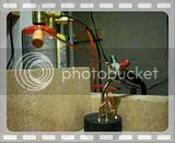
#70 The third diameter was cut at .170" between the two boss ends, (not shown in picture). I stopped the cut at the chuck end and brought my carriage mounted traveling rod forward and compressed the head stock mounted 1" dial indicator to the 1" mark. After moving the carriage .100" towards the tail stock I stopped and moved the cutter in .001". Again I moved the carriage .100" towards the tail stock and stopped to move the cutter in .001". I did this twenty times to create a gradual taper. It worked like a charm, typing this description up was harder, and took much longer. You can barely see the gradual steps in the picture below.

#71 Using the same tapered cutter I trimmed the out side ends to leaving just a small diameter for support. Using a file the steps were carefully blended away. After wards I used an Exacto saw on the small end after backing off the tail stock just a little but still offering support, and used a parting tool for cut-off on the chuck end.
Prior to filling, (I normally don't file on the lathe) as a safety precaution I wrapped the outer end of the chuck with a double layer of Duct Tape and rolled it over the chucks jaws. I'm right handed and my left forearm is an inch or so from the sharp edges of the spinning chuck. It took only one minute to put it on and to take it off, why should I take any chances.

#72 And there it is all finished up. I think it turned out very well, and I'm pleased.

#73 I enjoyed making it soooo much that I made a second one with a few minor changes. I made the boss on the crank end a little shorter, and reduced the second diameter on the pin end along with making it just a tad shorter. The hole spacing is identical and the two are interchangeable.

I always sleep well after a GOOD day in the shop. :big:
-MB
#61 I used a 'tenths' indicator to center it in the small four jaw for drilling and reaming the 'rocker shaft' hole. In this setup I also turned the 3/16" x 7/32" cylindrical boss on the one side shown in the drawing.
#62 To mill out the 1/4" x 3/8" opening took an unsettling set up that required the use of space blocks on the opposite end of the vise to balance out jaw pressure. It would have made a much better set up to have had an additional 1/8" added to the 7/16" dimension. It would be milled off after the opening was milled out by simply flipping it over. Live and learn. :
#63 Below is the finished 'rocker bearing'. The holes are clearance drilled for 4-40 studs. I won't be using the 3-48 specified in the plans due to not having the right size material to thread or the 3-48 nuts on hand. We do what we do out of necessity.
#64 The two piece 'crosshead guides' are next. After drilling the eight 4-40 clearance holes, I took the previously milled pieces and filed off the machine marks left by the end milling.
#65 In the plans Elmer suggests three cosmetic options that can be used on these pieces. Leave them plain, drill 5 spaced holes, or mill out an arch. Unfortunately there are no details like the dimensions, drill size, spacing etc.
I calculated for an 'arch' milled from the top down with the piece up side down in the vise. The machine moves are; one cut with a 1/4" ball end mill set to a depth half the height of the work piece using the "Y" axis (hope I got this right). Zero out on the end and move in along the "X" axis .350" for the first cut, and 1.710" for the second cut using the "Y" table movement. Switch to a regular square 1/4" end mill, set to the same depth and cut with one pass at.475" and 1.585" using the "Y" table movement. Finish up by cleaning out the remaining material between the last two cuts. This of course is my idea of the arch, you could shorten it a bit by adding 10 or 20 thousands to the first move on both end mill, and at the same time subtracting the same amount from the second movement of both end mills. This worked well, but I decided on using the drilled hole option on this build instead.
I decided to try five equally spaced 1/4" reamed holes. The work pieces were stacked laying on their sides in the mills vise. Why do all of this twice. After zeroing out on the outer edge, the table was moved along the "X" axis to .350", .690", 1.030", 1.370", and 1.710". At each location I center drilled, drilled, and reamed before moving to the next stop (location).
#66 After d-burring the holes by hand using a countersink, a light sanding with 600 grit sand paper,the parts are finished.
#67 The rest of this post is about how I made the 'connecting rod'. I feel proud of the new method I used today to create its tapered portion. On an rectangle of brass I laid out all the dimensions for tuning, and the locations of the 3/16" hole for the 'crank screw', and the 1/16" hole for the 'piston rod' pivot pin. After drilling and reaming the holes I centered it in the for jaw. I center drilled the end for a live tail stock center, and brought it out towards the tail stock end, leaving only a 1/2" the extra 3/4" of material on the chuck end in the chuck. The blank was originally cut one inch longer. A quarter of an inch was designated for cut off at the tail stock end, and the remaining three quarters of an inch allocated to the chuck end.
#68 Below is the first diameter of 5/16" cut all the way from the tail stock end to the chuck end, past the cut-off point at the chuck.
#69 The second .250" diameter was cut all the way from the tail stock to the scribed line designating the start of the boss on the crank screw end.
#70 The third diameter was cut at .170" between the two boss ends, (not shown in picture). I stopped the cut at the chuck end and brought my carriage mounted traveling rod forward and compressed the head stock mounted 1" dial indicator to the 1" mark. After moving the carriage .100" towards the tail stock I stopped and moved the cutter in .001". Again I moved the carriage .100" towards the tail stock and stopped to move the cutter in .001". I did this twenty times to create a gradual taper. It worked like a charm, typing this description up was harder, and took much longer. You can barely see the gradual steps in the picture below.
#71 Using the same tapered cutter I trimmed the out side ends to leaving just a small diameter for support. Using a file the steps were carefully blended away. After wards I used an Exacto saw on the small end after backing off the tail stock just a little but still offering support, and used a parting tool for cut-off on the chuck end.
Prior to filling, (I normally don't file on the lathe) as a safety precaution I wrapped the outer end of the chuck with a double layer of Duct Tape and rolled it over the chucks jaws. I'm right handed and my left forearm is an inch or so from the sharp edges of the spinning chuck. It took only one minute to put it on and to take it off, why should I take any chances.
#72 And there it is all finished up. I think it turned out very well, and I'm pleased.
#73 I enjoyed making it soooo much that I made a second one with a few minor changes. I made the boss on the crank end a little shorter, and reduced the second diameter on the pin end along with making it just a tad shorter. The hole spacing is identical and the two are interchangeable.
I always sleep well after a GOOD day in the shop. :big:
-MB


![DreamPlan Home Design and Landscaping Software Free for Windows [PC Download]](https://m.media-amazon.com/images/I/51kvZH2dVLL._SL500_.jpg)