Building a Bonzer Bonzer

Home Model Engine Machinist Forum

Help Support Home Model Engine Machinist Forum:

This site may earn a commission from merchant affiliate links, including eBay, Amazon, and others.
Yep Jim, another dog day today. On top of that, I saw my first baby "roo". Of course, when I told my friends I saw a baby "roo" hopping around in a friend's backyard today, they told me to start drinking carrot juice instead of budweiser.

Cheers,
Phil
 
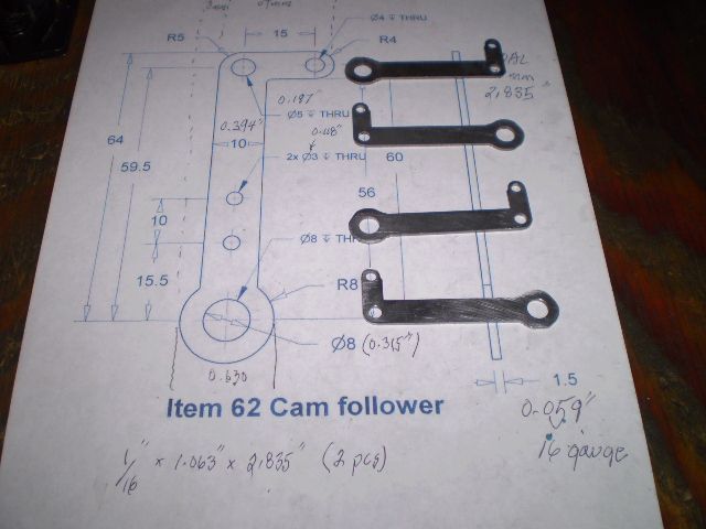
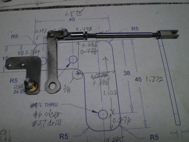
I'm making the cam follower for the engine. It consists of 2 outside plates that are 1/16" thick, that sandwich a roller bearing that the cam rides against and two pivot pins.

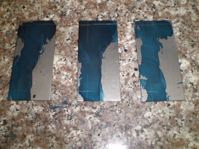
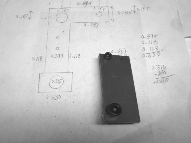
I decided to make the plates first, 2 are required and 1 spare. I don't have a lot of experience machining thin stock and pondered how to make these. I started by marking out the three holes for the pivot pins/bearing.


Once I drilled these holes I decided to make a 4th plate so I could bolt the plates together and have a workpiece that's 1/4" thick.


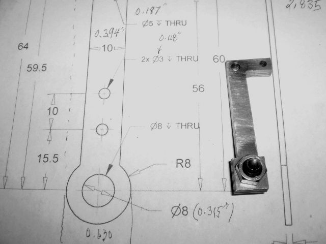
Then it was just a matter of sawing and milling to get the roughed out plates.


These look a lot like corner brackets you can buy for $0.25 apiece! That would make my labor worth about $0.05 per hour, a bit under minimum wage:p

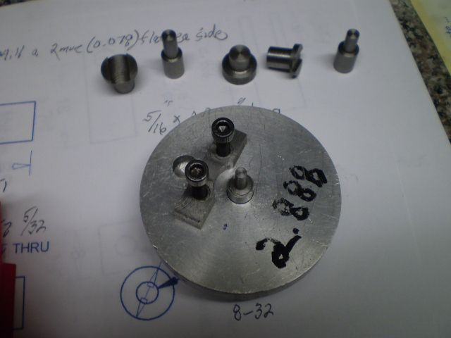
Finally, I had to round off the corners. I was going to use the bench sander with filing buttons for this job. But the bottom (largest) hole would need the rotary table to get around to the stem. So I got out the rotab and did them all that way. Years ago I made a fixture for the rotab and have made all kinds of fittings to hold a workpiece down. The fittings are various fractional diameters. Once I mount and position the fixture it's easy to attach my work to it for rounding off.


Finally the nearly finished plates.


A little touch up with the die filer to clean the sharp edges and they'll be done.

Making the pivot pins, and bearing will be a nice followup to the multi-step process for the plates.

Thanks for looking in.

Cheers,
Phil
 
I've been working on the exhaust valve operating mechanism. My current goal is to have an operating exhaust valve. There's a passel of small parts to make.

Here's progress so far:


I have a few more parts to make, rocker arm and mount, a few pivot pins then I can test the whole mechanism. Until the exhaust valve is operating properly no point in going forward.

I stopped midstream today to do some overdue PM on the small Grizzly mill. There is satisfaction that goes along with a nicely tuned up piece of machinery.

I will only return when I have an operating exhaust valve.

Cheers,
Phil
 
Hi Jim,
Thanks for checking in and the encouragement.

I'm looking at possibilities for flywheels. What do you think about these?

http://www.martinmodel.com/MMPflywheels-subfiles/FW060-6S-T-RG-XXXX-CI.html

They're 2.5 lbs apiece. Is that a bit much?

With a 5/8" diameter crankshaft I need to watch the hub dimension. I could also make my own but I'd need a hefty cutoff from my cast iron source and at 5 lbs/in, a 6 inch piece runs 30#, if they have it.

I've asked Jan Ridders for a drawing of his vapor carb.

http://ridders.nu/Webpaginas/pagina_benzinedamp_carburateur/dampcarburateur_frameset.htm

I think I'll try the model out with that carby.

Cheers,
Phil
 
Those flywheels look great Phil, they should turn up nicely.

I turned mine from square mild steel 1" thick cut off from a bar by the steel supplier. Lots of interrupted cuts and then a couple of garbage bins full of blue swarf.

Your way is better.

Jan Ridders' vapour carby is a good way to start. Chuck Fellows built one using a Pimento Jar - you might find it on HMEM (or a PM to Chuck).

Jim
 
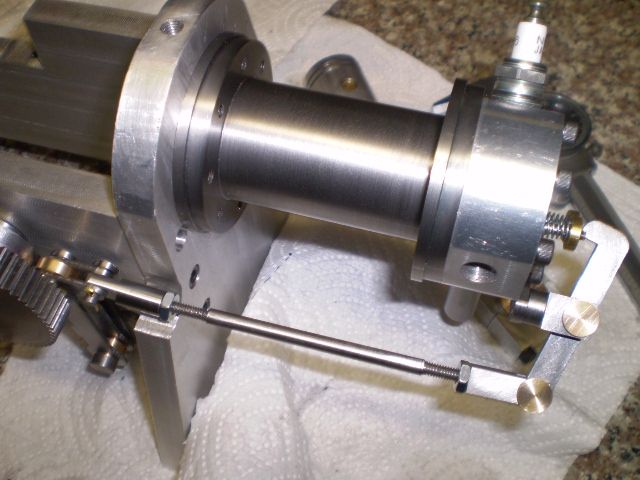
I've reached another goal, sort of, and that was to have a working exhaust valve train. With all the parts assembled and a temporary cam set screw I'm able to actuate the exhaust valve by rotating the camshaft:


A few problems have surfaced, though nothing I can't fix. The rocker arm mount position needs to be accurately placed and I can't move it small amounts once it's installed because the mounting screw is inaccessible. The arm is only 0.125" thick and I'm thinking of remaking one that's thicker at least where it contacts the valve stem. Then I can get the mount close to where it needs to be and locktite it in place.

Another problem is the cam follower. As I made it the tolerances are too sloppy so it has a lot of side play. Now that I see where it's position is, I can make a new pivot pin to much closer tolerance.

I also want to add about 3/4" to the valve rod length because it's only attached at either end with a few threads.

So, nothing too serious to worry about and considering all the parts in this assembly, a few remakes are to be expected.

Thanks for looking in

Cheers,
Phil
 
I don't recall how I adjusted the rocker arm, I think I set it up with the screws just pinched up and then took it off to tighten it. I do remember that the positioning was critical; the original engine had a double bend in the valve rod taking it under the cylinder and I wanted to eliminate that.

Sorry about the valve rod length, as I think I mentioned, I didn't have Alibre when I built the engine so the drawings were done from the finished engine. I probably measured it incorrectly.

Cabin Fever is still about 18 weeks away:eek: so you have plenty of time;D

Jim
 
Hey Jim,

Sorry about the valve rod length
Actually 100 mm works OK, as you specified. I noted the original Bonza used 112 mm. I think 112 mm will allow me to fully thread those end connectors on which hopefully will add rigidity.

Cabin Fever is still about 18 weeks away
Man, you are really applying the pressure *bang*. Hey, would you settle for a simple steam engine instead?

Cheers,
Phil
 
Last edited:
The exhaust valve train is a relatively delicate assembly. I studied the action and found a few connections that needed a bit of adjusting and I'm very pleased with their operation now.

I think the only mod I'll go ahead with is a thicker rocker arm to give me just a bit of wiggle room for the contact area of arm - valve stem.

I'm also just now understanding the governor operation. I'll add that after I have an operating engine.

The next item to tackle will be the piston rings. I made one for the last engine I built, a steam engine that I operate on compressed air. I don't think I tested my ability to make one for an IC engine but I am a persistent fellow. That, and my access to a good supply of inexpensive CI means sooner or later, I should have some good results to show

As usual, thanks for looking in

Cheers,
Phil
 
Thanks Al. Had to see what a Sprag Clutch was. Seems complicated :confused: but clever.

I've made two sets of four piston rings, the sets differ by 0.004" thickness. I made these using a technique some of my fellow modellers described to me. And I think Model Engineering magazine had an article in early 2013 with the same process.

Basically, make the OD of the ring oversized (by 0.060" in my case). Make the ID of the ring about 0.006" more than the ring groove base in the piston. Part the rings, split them by a number of techniques, file the ends smooth. Make a clamping fixture, clamp the ring so its proud of the fixture with the ends butted. Turn the ring to the bore size.

Here's a picture sequence:

Drill out the cast iron
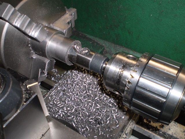

bore to size
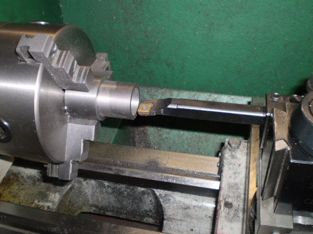

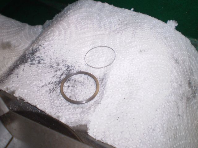
Turn the OD to size, then part the ring off. The ring is in the foreground here, and the very thin ring behind it falls off the workpiece when a very slow feed rate is used near the end of parting. Almost no burr is left on the ring.


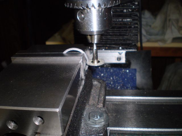
I split the ring with a 0.020" thick slitting disk:


Here's the piston, 2 sets of rings and the clamping fixture
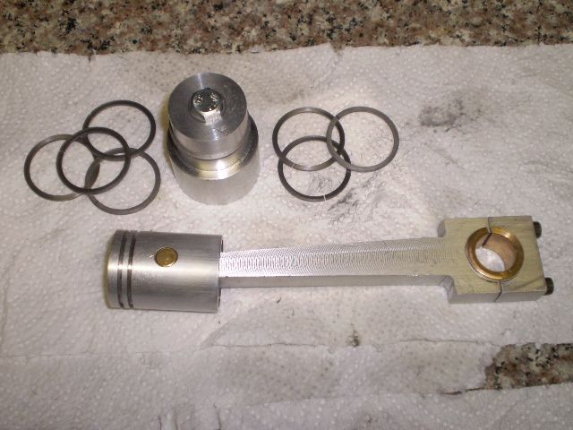


And the ring in the fixture ready for turning. In this picture I haven't closed the ring gap yet
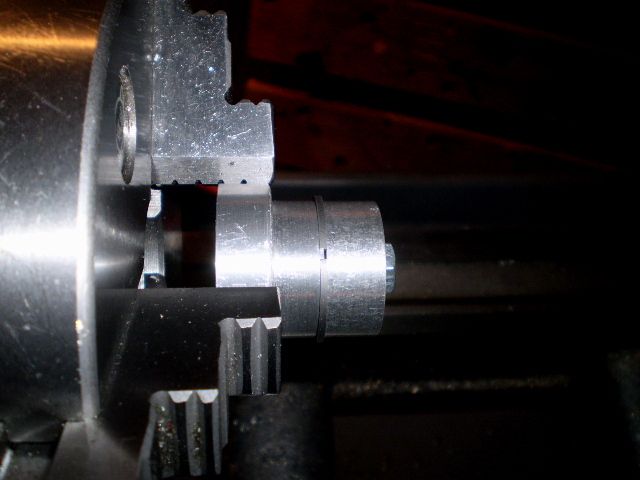


Next few days I'll be doing some turning, fitting and perhaps I'll make a ring compressor so I can get the piston in the cylinder.

Thanks for looking in

Cheers,
Phil
 
Had to see what a Sprag Clutch was. Seems complicated :confused: but clever.

Oops, bit of jargon from my bearing industry days slipped in. You can get 'one way bearings' which incorporate a sprag clutch internally, so we just called them a sprag as shorthand. Easy to buy, many sizes available and very useful. Drive the bearing backwards and it will turn the shaft with it, when the engine starts it will overrun the bearing freely. Just a bit of info to tuck away for future use.

If I haven't already said so, your engine is looking fantastic, can't wait to see it running.
 
Thanks Al. I broke 2 piston rings turning the OD. Very light cuts, 0.003" at a time only. A bit more and they break. I got two rings on the piston, and got the piston into the first cylinder (botched) I made. That should act as a ring compressor so I can push the piston into the "real" cylinder.

Making piston rings seems like 50% science and engineering, 50% art and 50% dumb luck :rolleyes:

Still on the learning curve. The carby will be a challenge. Jan Ridder's vapor carb, Brian Rupnow's check valve. So I've got Australia, Canada, Holland and the USA involved in this project. If it doesn't run there'll be an international "incident".

Cheers,
Phil
 
Thanks Jim.

I got the engine assembled with all the parts I've made so far. I really have to study this engine to get the valve operation working properly.

I know the valve won't normally be fully open at TDC but I found the exhaust valve will hit the piston at TDC, is that normal for the design? If so, eventually I'll want to make the attachment of the cam to its gear hub permanent.

I can get compression if I really put tension on the valve springs, but then the cam slips when it starts to lift the valve. I'll have to fiddle with some other springs and also play with the valve rod length.

But the good news is "compression" which means the valves and piston rings are working. Whether they're up to the job remains to be seen.

So it seems I'm about ready to order the flywheel castings.

Cheers,
Phil
 
I know the valve won't normally be fully open at TDC

Did a bit of reading Malcolm Stride's Book "Miniature IC Engines" last night. The exhaust valve is normally open at TDC so valve contact with piston means my valve travel was too far.

That was easily fixed today by adjusting the effective push rod length. So now I have compression, with a little flywheel bounce back, valve operation looks good.

Is the compression good enough? I guess time will tell. It wouldn't be a tragedy if I had to go back and make better valves/seats or piston rings. The way things are fitting together keeps me motivated.

I know all this has probably been covered hundreds of times in other posts but until 5 months ago I never thought I'd be making an IC engine. One of these days I'll need to spend some time reading some of those.

I'm going to start on the Ridder's fuel tank/carby as soon as I can locate a source of acrylic or glass round disks for the end window. Ebay sellers list them by the pack of 100, but I'd like to find just a few.

Thanks for looking in. As usual, comments and advice are welcome

Cheers,
Phil
 
Philjoe--Go to your resident watch repair guy. He will have a selection of different sizes for watch crystals (as in pocket watch). A trick that I found out with i.c. engines--Hook everything up, mount your gas tank and sparkplug, set your timing to where you think is right, turn on your ignition, then drive the engine at about 500 rpm with an electric motor and a v-belt set up. That way you can tweak the carburetor and timing settings until you get the engine firing consistently. Once it has ran this way for 5 minutes or so, it will develop a tremendous increase in compression and start to run on its own. The combustion pressure when the engine begins to fire seems to do miracles for sealing the valves completely, even if they had a small leak to begin with.--Brian
 

Latest posts

Back
Top