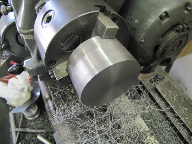
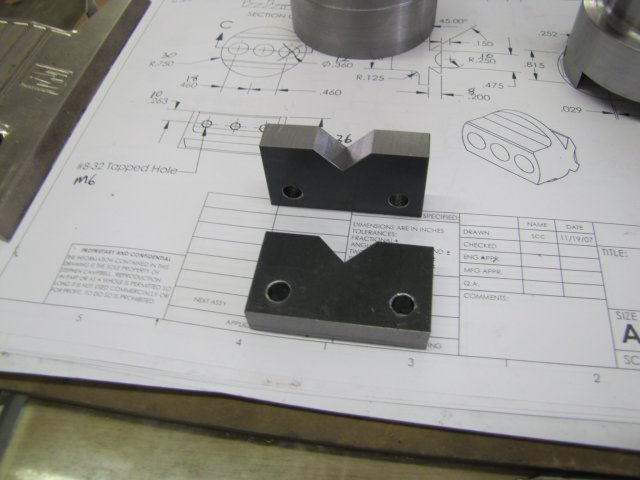
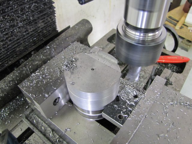
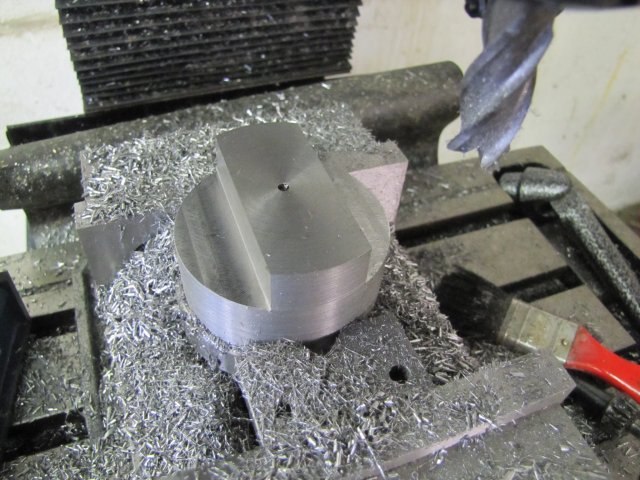
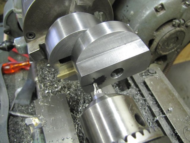
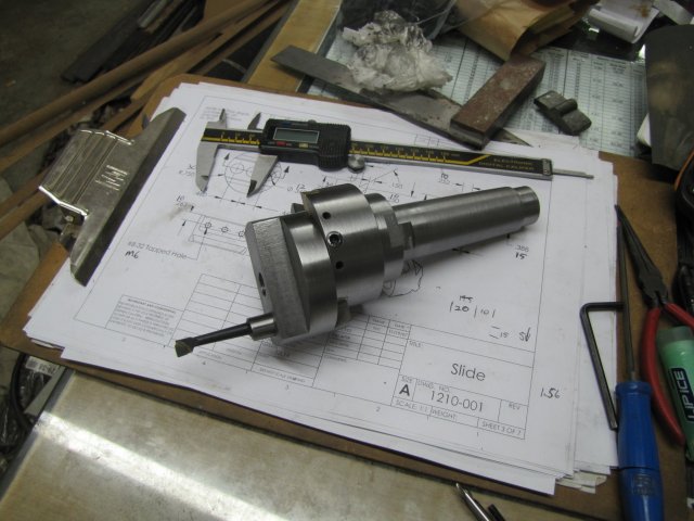
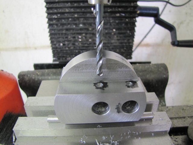
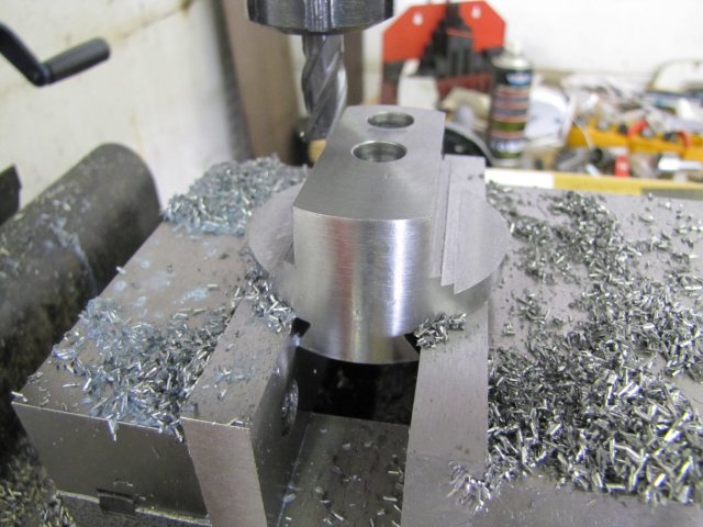
Finally - the boring head is done ;D Quite a big update, so my apologies if things are a bit slow to load in your browser!
The leadscrew needed making... Steve and Dean used modified cap screws; a perfectly good solution. I didn't as I wanted a 0.5mm pitch lead screw, and M6x0.5 cap screws are unobtainable locally, so I had to do a bit more work than really necessary.
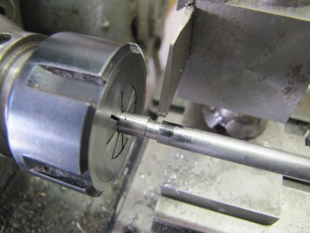
I started off with a bit of 6mm silver steel in the collet chuck on the lathe and parted a 4mm wide groove in it to 4mm diameter. This groove becomes both thread run-out, as well as the groove that the retainer slips into to keep thinks in place when the boring head is assembled, so it was carefully marked off at the appropriate length along the workpiece:
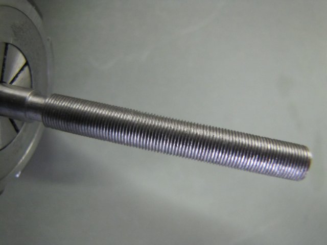
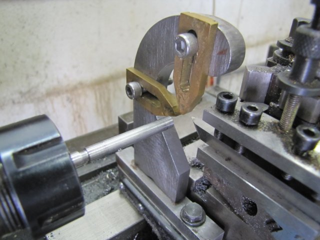
On to threading; I have single-point turned a couple of threads in the last 2 years, but this one was new territory for me. It is by far the finest I have attempted, and there would be definite flex in the workpiece. To make sure I had no unexpected surprises from the drivetrain, I cleaned all the change gears and the lathe's lead screw much more meticulously than I usually do - not that I'm not meticulous with this part normally - today I was just about anal about it. I also dug out the traveling steady I made as one of my earliest projects for the lathe. Last, but by no means least, I spent quite a while honing my HSS threading tool to as sharp a point as it ever had; on this fine thread, only the last 0.25mm (10 thou) of the tip will be used, but the cutting angle must be accurate and sharp there. This is the setup - ready for threading:
Seeing as this thread was for metric, I had to keep the feed nuts engaged and reverse the lathe after each cut, so I wasn't too keen on taking that many passes... First cut was at 7 thou infeed with lots of cutting fluid, then another 3 thou added, and run through again at the same setting to clean up a bit. This is the result at that point:
I was concerned that it looked a bit rough at this point, but a quick run-past with a small wire brush cleaned of the gunk, and the feed nut screwed on easily but without any play or roughness ;D
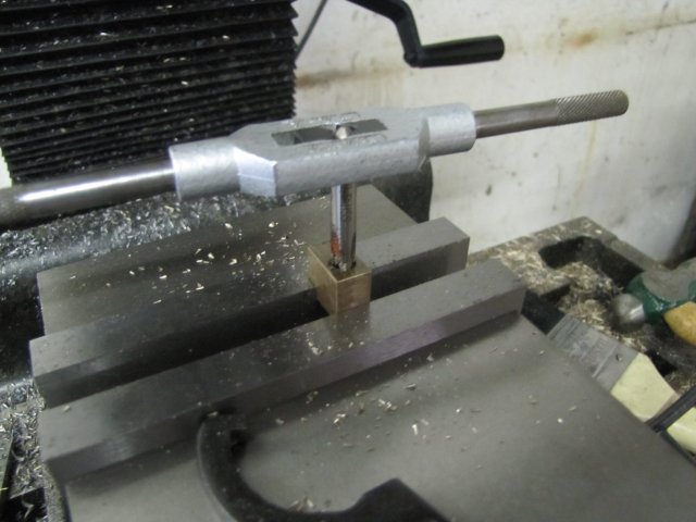
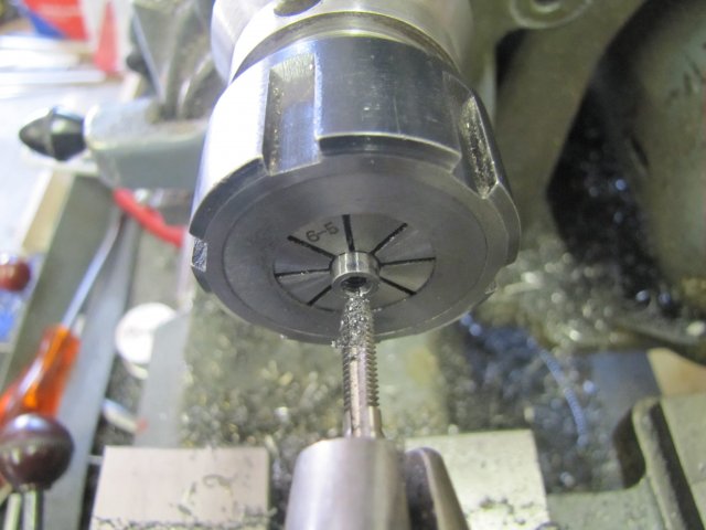
Then I sawed of the leadscrew-in-making 10mm beyond the parting cut and chucked it in the collet chuck with the sawn-off face pointing out. This was faced off, and drilled and tapped for M4:
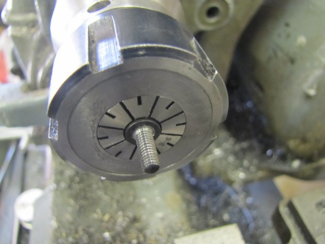
An M5 cap screw was then chucked by its "cap" in the collet chuck with the thread sticking out. I turned down the threaded section to 4mm, and re-threaded it to M4:
Some excess length was then sawn off.
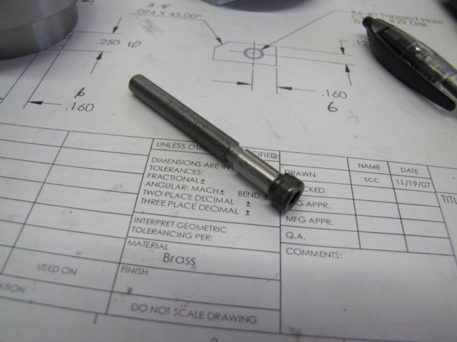
The above was a lot of boo-hah just to get to this point:
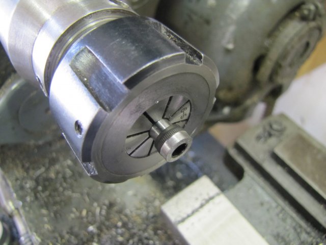
Next the leadscrew was chucked up in the collet chuck once again and the cap screw thoroughly and forcefully screwed into the leadscrew, effectively completely seizing it up thoroughly. Then I turned the head down to 8mm OD for a distance of 3mm:
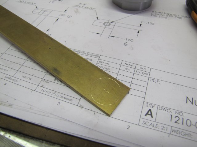
Some 3mm brass plate was marked up:
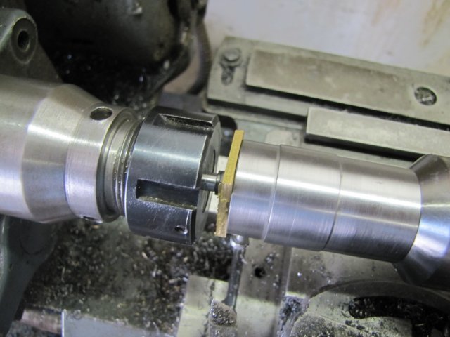
Then sawn off, and drilled with an 8mm hole in the center. From some previous "Fun", I know that my 8mm drill will drill a slightly triangular hole in thin brass plate, and I used that to my advantage in this case. The hole actually ends up JUST below 8mm nominal diameter, so becomes a light press fit on an 8mm round section - I used the tailstock holder which happened to still be sitting in the tailstock to just press the piece of plate over the head of the cap screw:
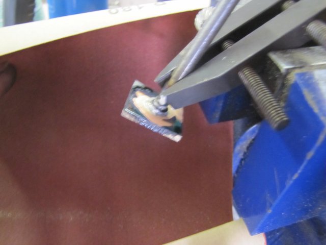
Then I took the workpiece, clamped it in a toolmaker's vise in the big vise, and silver brazed the plate to the cap screw:
( :-[ Sorry - photo out of focus)
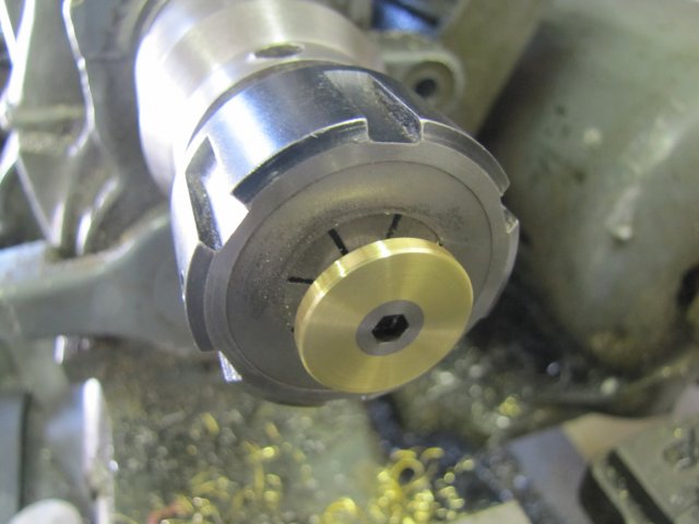
A bit of cleanup in the collet chuck later:
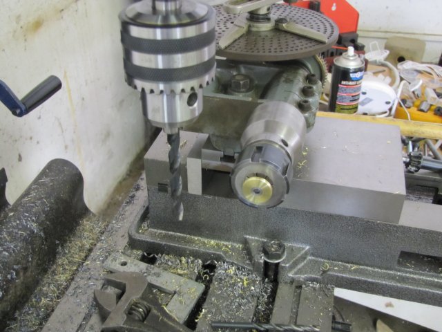
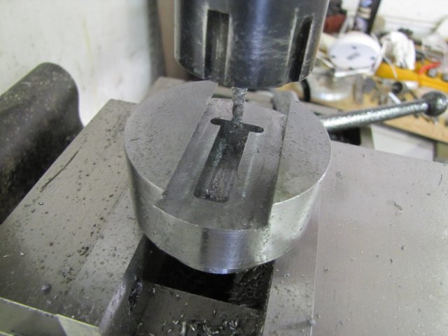
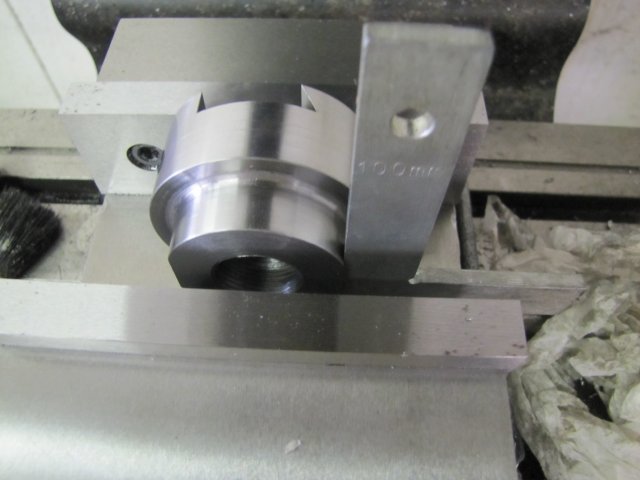
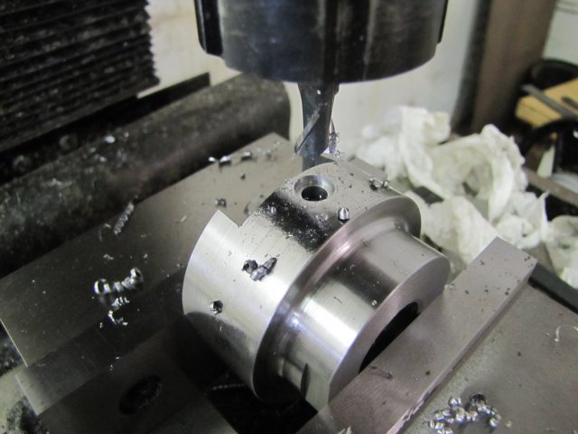
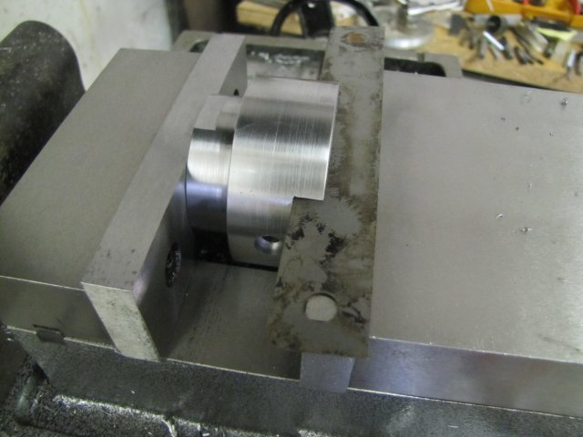
I love the new mill vise; instead of the elaborate setup I needed for making graduations when I built the rotary table, I could just clamp the cross-slide extension I made for the lathe in the vise and mount the dividing head on it:
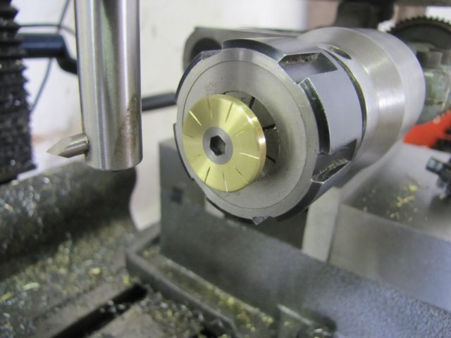
A simple run-through with the same tool I made for graduating the rotary table, and I had 10 large graduations on the dial:
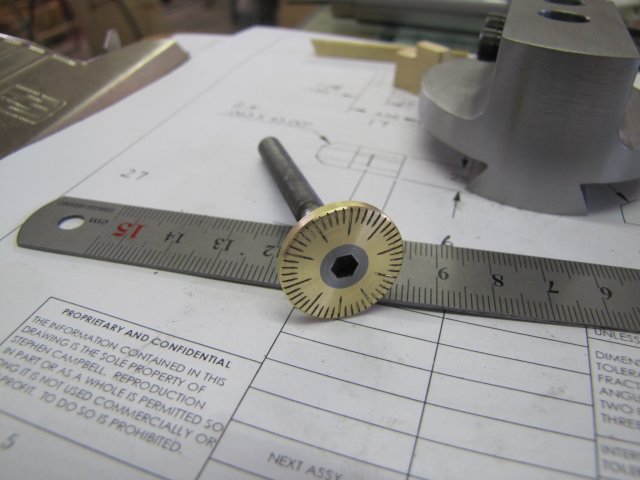
This was followed by 50 shorter markings. Initially I thought about 100 marks, but 50 is plenty close enough and gives me 0.01mm feed on the leadscrew per mark (0.02mm diameter increment). I can still "guestimate" settings between marks, so this should be plenty accurate enough for my needs:
(I rubbed a dirty oily finger over the marks to make them stand out a bit)
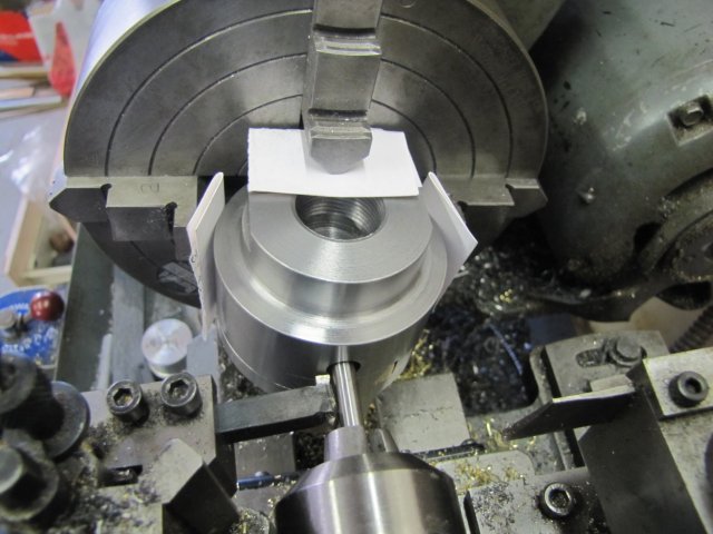
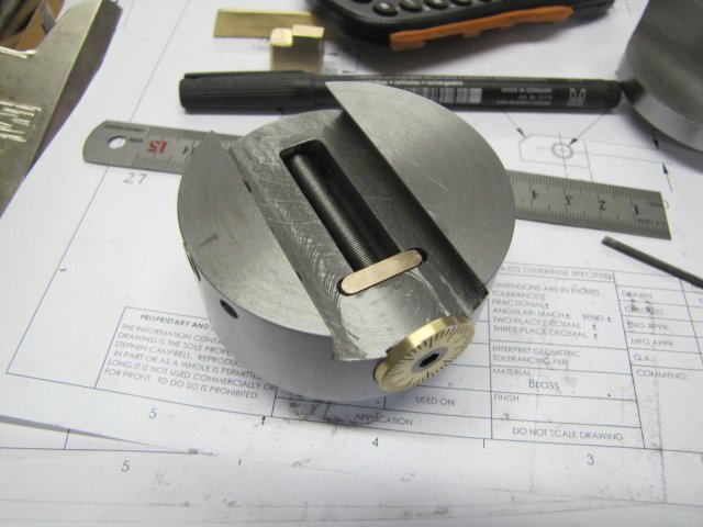
Next up, boring a recess for the dial in the B/H body... This was not a simple task, and it would have been nice to have a boring head to do the job :

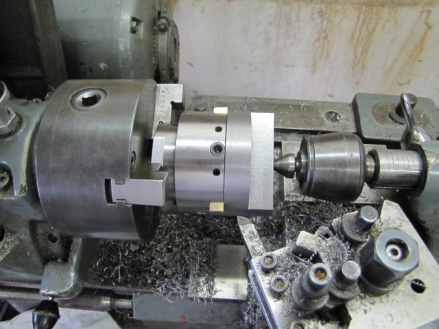
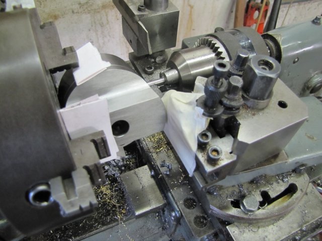
Dean did this step on his rotary table, but I could not figure out a way to reliably clamp the boring head to my RT, as its a bit small compared to the B/H... So I ended up on the lathe, with the 4-jaw, and a piece of 6mm silver steel to align things and keep the operation safe. I used the dual-headed turning tool I made earlier in this thread for the boring. A couple of drops of oil on the silver steel held in the tailstock chuck, and pushed ALL the way through and engaging the back end of the B/H where the lead screw would end in, and things were moderately safe and aligned for turning:
Tolerances would be close, so instead of risking smashing the boring head body into the toolpost, I used two layers of masking tape to provide for warning; if the tape got caught, limits would be very close indeed!:
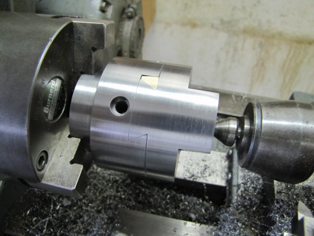
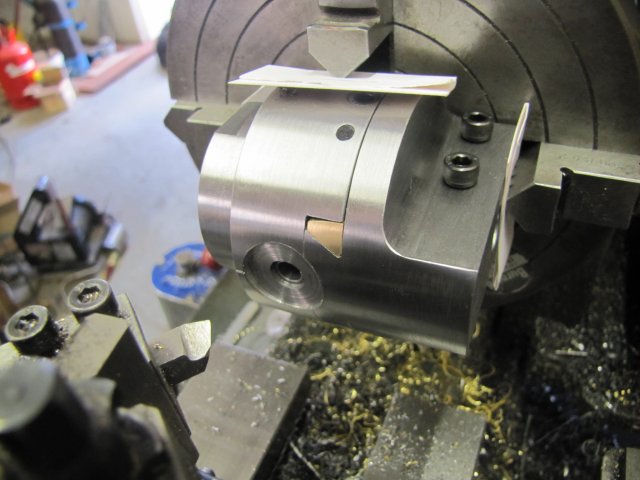
With the lathe at high back-gear speed, I bored out the recess - very gently. This setup was not very rigid, so I erred on the side of caution and safety. After boring out the recess, I used my normal cutting tool make the scale reference mark on the body - a couple of quick traverses with the cross-slide (one too many in fact), and the mark was there (on the body just to the top right of the cutting tool tip in the photo):
One too any, as the mark ended up a bit deep for my personal preference...
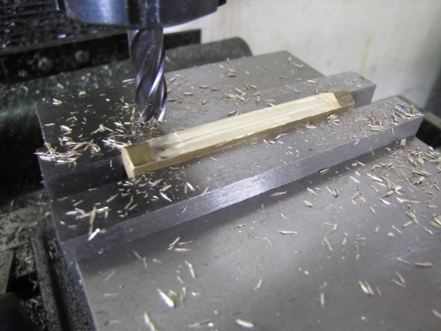
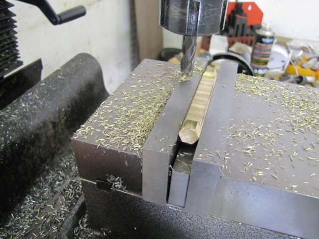
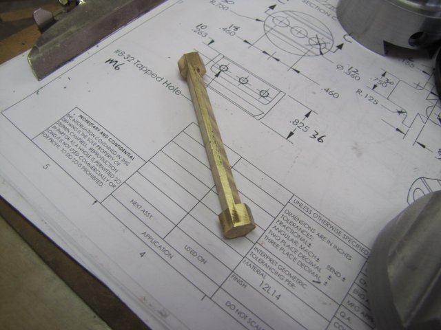
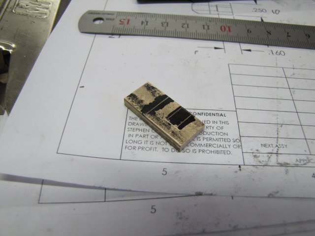
Next up, the lead screw retainer - all marked up on some stock:
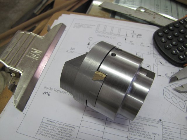
:-[ I thought I'd taken a photo of the retainer as-finished, but I didn't! I milled it to size and filed roundings on the outside edges, and it slipped in in position. I was a bit over-vigorous on the rounding over though!:
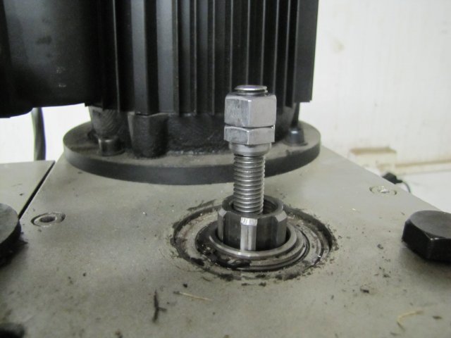
Then I assembled everything, and ran into a minor snag... My 12mm draw bar is a Weeee bit long :-[. I don't have a sufficient length of 12mm threaded rod left for making a new draw bar, so some shopping required after the weekend to make a new one for the boring head:
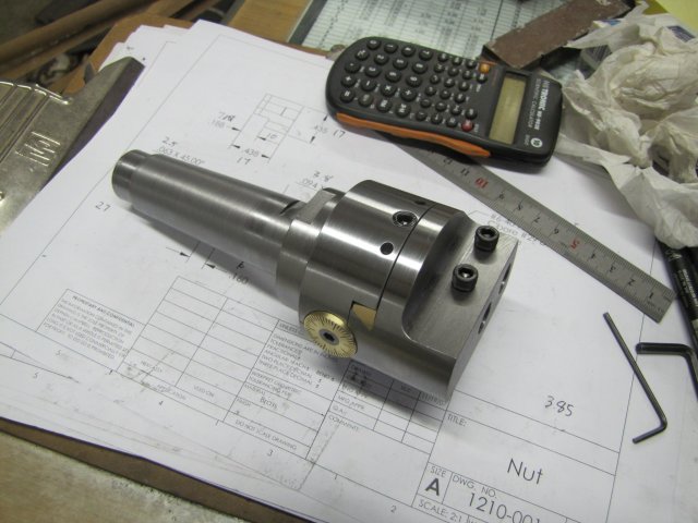
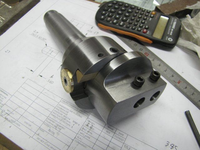
Besides the draw bar issue, the B/H is completed though not tested ;D:
By no means a perfect job, but I'll settle for this. Operational testing will have to wait till I get a length of all-thread to make a draw bar for it, but I just think it may work ;D
All-in-all, it appears to work as intended; I have very little backlash on adjusting the head, and all adjustments are nice and smooth, so I'll call this one finished.
This was an immensely enjoyable little project with it's own set of challenges and first-for-me operations. ;D
Special thanks go to Steve C and Dean - for sharing so unreservedly from your own experience!
Thank you also to all who followed along and especially those who contributed to this little quest :bow:
Kind regards, Arnold
 - There's not much "outside of the box" though; just applying (or at least trying to apply) some basic machining practices that was in use well over a century ago already - and that somehow seems to be receding into the mists of time.
 Maybe I'm lucky to have more limited access to all the doo-dads thats available at the drop of a brown package in a short time overseas ;D
 - yes, a quick un-hardened once-off cutter for brass would work




![DreamPlan Home Design and Landscaping Software Free for Windows [PC Download]](https://m.media-amazon.com/images/I/51kvZH2dVLL._SL500_.jpg)


