
You are using an out of date browser. It may not display this or other websites correctly.
You should upgrade or use an alternative browser.
You should upgrade or use an alternative browser.
Building #52, Elmers RVTW
- Thread starter Metal Butcher
- Start date


Help Support Home Model Engine Machinist Forum:
This site may earn a commission from merchant affiliate
links, including eBay, Amazon, and others.
- Joined
- Dec 28, 2008
- Messages
- 1,731
- Reaction score
- 9
1hand said:What you think of this Idea...........Getting a 6" 4jaw and instead of the 4" get a 3" 5c 4jaw chuck. Being I have the 5c on the lathe now. Would the 3" be useless do to its size for most of the Elmer's engines? I thought it would be nice for them lathe to mill transfers. I already have a 5c Indexer for the mill. Wouldn't have to re chuck and would save me an additional back plate to make.
Getting a 6" four jaw is probably a good idea. Have you tried to use the factory supplied four jaw lately? ;D
Do you mean to mount a chuck into a chuck? Sounds a little chucked up. You could transfer the collet from the lathe chuck to the 5C Spindex by un-chucking and re-chucking.
You won't save any time during lathe to mill transfers, you would still have to un-chuck and re-chuck the chuck! Say that real fast three times.
If its square work, then the 'vise will suffice!' Kinda rhymes don't it? If you decided to add a 4" 4-jaw later the back plate is only $18 from LMS.
Got collet blocks? Oh no, here we go!
Slow down, were gonna run otta money here!
-MBI
-MBII
oops, meds are wearing off, again. :big:
- Joined
- Dec 28, 2008
- Messages
- 1,731
- Reaction score
- 9
Dreeves, That's a real beauty! :bow:
You made a lot more changes than you'll see on mine.
Wish you would have posted earlier so I could have 'borrowed' some of your ideas. ;D
Super job. Thanks for posting the pictures.
-MB
You made a lot more changes than you'll see on mine.
Wish you would have posted earlier so I could have 'borrowed' some of your ideas. ;D
Super job. Thanks for posting the pictures.
-MB
Sorry to clutter your build page, but what I was getting at is.......say you got a square part and you need to turn a boss on one end. So you put it in the 4jaw on the lathe. now you got drill and tap a circle bolt pattern on the boss you just turned, so you then take the 4jaw 5c collet chuck out of the lathe tansfer it to your 5c mount on the mill. The piece stays mounted in the 4jaw that you carefully had all centered up while it was in the lathe. your 5c mount was all centered up in the mill a head of time, so you tighten the collet chuck down, move your off set and start drilling.
This is kinda what I was referring to.
Matt
see how I wear myself out!!
This is kinda what I was referring to.
Matt
see how I wear myself out!!
- Joined
- Dec 28, 2008
- Messages
- 1,731
- Reaction score
- 9
1hand said:Sorry to clutter your build page, but what I was getting at is.......say you got a square part and you need to turn a boss on one end. So you put it in the 4jaw on the lathe. now you go to drill and tap a circle bolt pattern on the boss you just turned, so you then take the 4jaw 5c collet chuck out of the lathe transfer it to your 5c mount on the mill. The piece stays mounted in the 4jaw that you carefully had all centered up while it was in the lathe. your 5c mount was all centered up in the mill a head of time, so you tighten the collet chuck down, move your off set and start drilling.
This is kinda what I was referring to.
Matt
see how I wear myself out!!
Matt,Your not cluttering anything up. I'm interested in learning how to machine and the four jaw chuck and other issues are becoming a very important part of my engine project. Seeing that you have very similar needs along with having an identical lathe allows use to knock around ideas and solutions to fulfill present and future needs.
I think I understand what your saying about transferring the square work from the lathe to the mill. I would transfer the square work to the mill vise and zero out on its edges to drill the bolt pattern on the round lathe turned part of it. If you have a vertical indexer on the mill the idea should work well. I have a horizontal 5C spin fixture that won't work for a 'face on' bolt pattern. I've seen the 5C collet chuck your talking about and never understood how it could be used beneficially other than the ability to chuck up an odd size for mounting in a spindex. As far as anything like chuck being too small or to big was just proven to me with the need for a 6" four jaw. I imagine most would have said its a little big, but remember our lathes are a 9" swing short bed. If I had bought a 4" or 5' 4-jaw I would have been in trouble today, as a matter of fact if the piece were a 1/4" longer I would have needed to exceeded the 6" chucks listed capacity to make it work. Then the only other choice would have been a more tedious boring of the hole in the mill.
-MB
The bottom line is that the 6" 4-jaw is a necessity that works and fits our lathes.


$29.95
Competition Engine Building: Advanced Engine Design and Assembly Techniques (Pro Series)
Amazon.com Services LLC


$40.02
$49.99
Becker CAD 12 3D - professional CAD software for 2D + 3D design and modelling - for 3 PCs - 100% compatible with AutoCAD
momox Shop


$24.99
$34.99
Bowl Sander Tool Kit w/Dual Bearing Head & Hardwood Handle | 42PC Wood Sander Set | 2" Hook & Loop Sanding Disc Sandpaper Assortment | 1/4" Mandrel Bowl Sander for Woodturning | Wood Lathe Tools
Peachtree Woodworking Supply Inc


![DreamPlan Home Design and Landscaping Software Free for Windows [PC Download]](https://m.media-amazon.com/images/I/51kvZH2dVLL._SL500_.jpg)
$0.00
DreamPlan Home Design and Landscaping Software Free for Windows [PC Download]
Amazon.com Services LLC

Right, I have both the 5c indexer and the vertical/horz. mount also. I guess my biggest concern is trying to rotate odd shape pieces on the mill. I guess another avenue to go would be turn a plate with a spindle that matches my lathe to fit on my RT. That way I could use the 4jaws, 3jaws, and 5C chucks on both the lathe and mill just by spinning them off and spinning them back on. Then instead of having two of each chucks and separate back mounting plates every thing would be interchangeable with each other.
So my next Question issssssssss...............Will our lathes turn a M39x4 Thread?
So my next Question issssssssss...............Will our lathes turn a M39x4 Thread?
If you think I freak show yet..................
Here I need to rotate on both axis's using the same reference point. Where if I had a chuck I could remove from machine to machine staying spot on would of been easier.
Matt
Here I need to rotate on both axis's using the same reference point. Where if I had a chuck I could remove from machine to machine staying spot on would of been easier.
Matt
- Joined
- Dec 28, 2008
- Messages
- 1,731
- Reaction score
- 9
1hand said:Right, I have both the 5c indexer and the vertical/horz. mount also. I guess my biggest concern is trying to rotate odd shape pieces on the mill. I guess another avenue to go would be turn a plate with a spindle that matches my lathe to fit on my RT. That way I could use the 4jaws, 3jaws, and 5C chucks on both the lathe and mill just by spinning them off and spinning them back on. Then instead of having two of each chucks and separate back mounting plates every thing would be interchangeable with each other.
So my next Question issssssssss...............Will our lathes turn a M39x4 Thread?
That's a set-up that's crossed my mind. It would be much easier then machining individual flat back plates that could be bolted to the RT. My lathe spindle is 1-1/2"-8 thread.
One thing at a time. I got an idea! Why not get your 6" 4 jaw and back plate ordered, and start your #332 build project. Add tooling, other chucks, and fixtures when you need them, or when you need to take a break away from your build?
-MB
- Joined
- Dec 28, 2008
- Messages
- 1,731
- Reaction score
- 9
1hand said:If you think I freak show yet..................
Here I need to rotate on both axis's using the same reference point. Where if I had a chuck I could remove from machine to machine staying spot on would of been easier.
Matt
What the he..!
I feel a headache coming on.
- Joined
- Dec 28, 2008
- Messages
- 1,731
- Reaction score
- 9
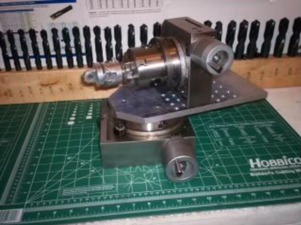
#52 The picture above looks like an attempt at breeding rotary tables. Havin any luck? :big:
The picture below was staged after the fact. I forgot to take a picture and lightly re-chucked the part to shoot the picture. After 'picture guy' posted the pics I realized I forgot to re-install a rectangular saw cut backing piece that was used between the work piece and the face of the chuck to assure that the work piece wouldn't shift backwards during the drilling and subsequent boring of the clearance opening for the crankshaft.
My new 4-jaw chuck worked flawlessly, and proved to be a wise addition for my lathe. I'm so glad I mustered up the courage to buy, and learn how to use one. Its hard for me to believe how simple it is to dial in a work piece to within a few tenths.

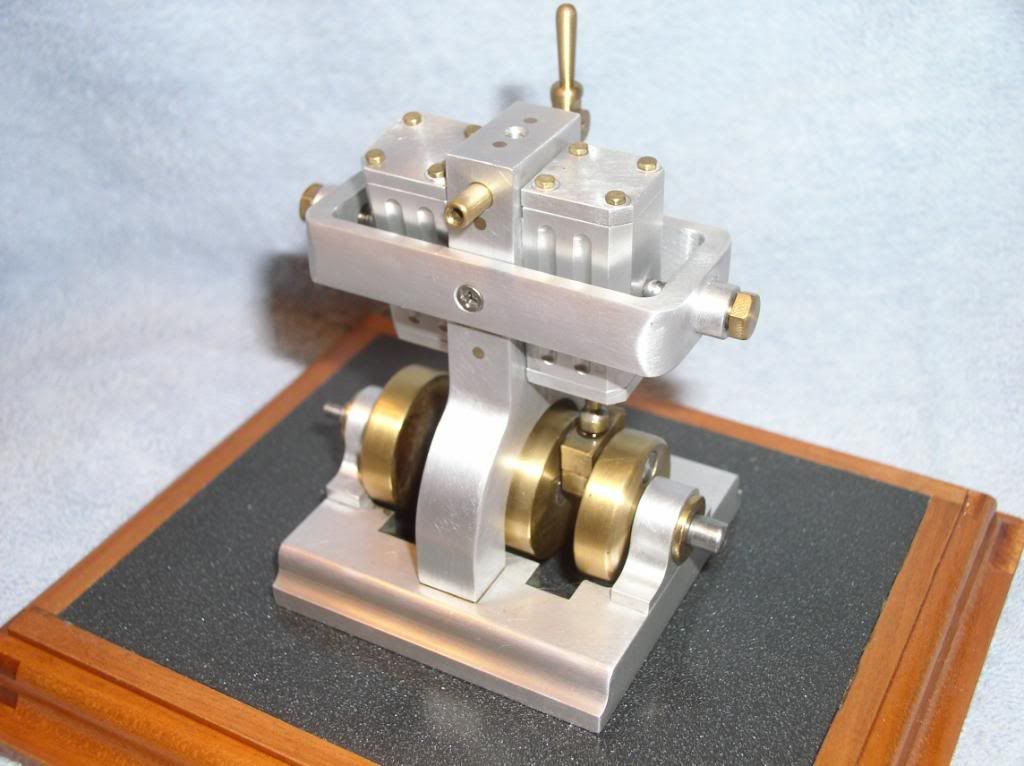
#53 After boring out the crank shaft opening, the out side profile was cut at a 45 degree angle. I like to alter plans to suit my taste, and the elimination of the curved profile was planed before I started this build. All that's left to do on the 'column' is to mill out the 1/8" slot for the 'Lever'.

#54 I assembled the three structural pieces to see if every thing lines up, and all is well.

#55 The valve started out as a stock oversize (length wise) piece of square 1/4" brass bar. I milled out the opening for the 'Lever', and drilled the port holes first to simplify these steps while the valve material was still square.

#56 To turn the cylindrical parts of the 'Valve' my 4" chuck was installed. To remove the 6'' four jaw and replace it with the 4" took only two minutes. To dial in the workpiece within a 'tenth' took only a few more minutes. I still can't believe how easy this is, and I find the process relaxing and enjoyable.
A few years back I bought two of the indicator seen in the picture. At the start of my machining season back in November I looked at the tools in my collection and saw the cute little indicators in their fitted blue boxes. I thought to myself "why did I buy these", since I never had a use for them.

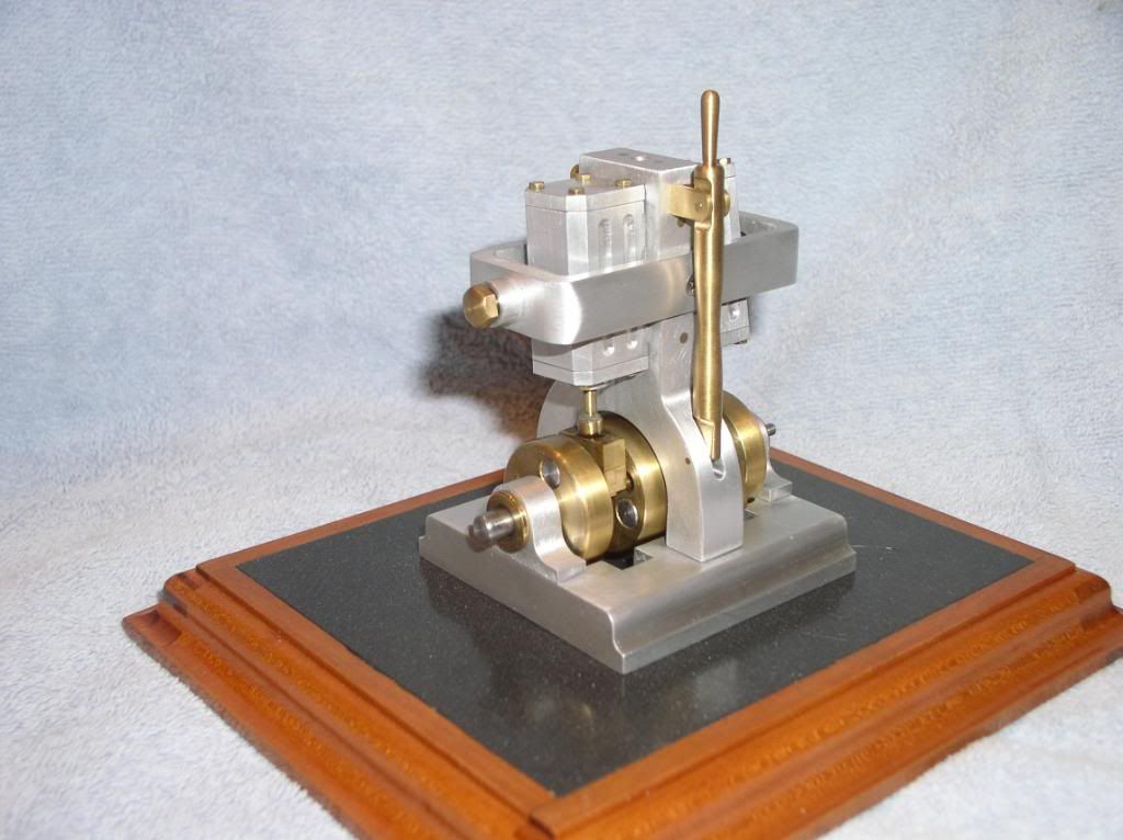
#57 After machining the two diameters I drilled the port hole from the threaded end to connect the two previously drilled cross port holes. I threaded the end for the 3/16" nut that was made up earlier along in the build. After checking all the measurements I parted off the 'valve'.
When I went to test fit it in the 'column' the ports didn't line up when the valve was pulled up against the stop nut! When it was pushed in against the square lever side, those ports lined up perfectly. After looking over the drawing under magnification it became apparent that the section I threaded was supposed to be cut- off, and the threaded section stopped at 1-7/32" and not the 1-5/16 dimension I followed in the lower drawing. The absence of the center drilled detail in the lower drawing threw me off! The fix was quick and simple. I reduced the diameter in the proposed area with a file, and carefully threaded for the nut to reach the 1-7/32" dimension. Then I cut off the excess threaded area with an Exacto Saw. It turned out well and left no evidence of the mishap. As they say, 'All is well that ends well."
In the picture below you can see that the nut is farther away from the port holes than the square section for the 'lever'. I didn't notice this until the pictures were uploaded earlier in the day. I went back down to the shop for the test fitting to see what the problem was, and fixed the problem with out any need to start all over again.

-MB
The picture below was staged after the fact. I forgot to take a picture and lightly re-chucked the part to shoot the picture. After 'picture guy' posted the pics I realized I forgot to re-install a rectangular saw cut backing piece that was used between the work piece and the face of the chuck to assure that the work piece wouldn't shift backwards during the drilling and subsequent boring of the clearance opening for the crankshaft.
My new 4-jaw chuck worked flawlessly, and proved to be a wise addition for my lathe. I'm so glad I mustered up the courage to buy, and learn how to use one. Its hard for me to believe how simple it is to dial in a work piece to within a few tenths.
#53 After boring out the crank shaft opening, the out side profile was cut at a 45 degree angle. I like to alter plans to suit my taste, and the elimination of the curved profile was planed before I started this build. All that's left to do on the 'column' is to mill out the 1/8" slot for the 'Lever'.
#54 I assembled the three structural pieces to see if every thing lines up, and all is well.
#55 The valve started out as a stock oversize (length wise) piece of square 1/4" brass bar. I milled out the opening for the 'Lever', and drilled the port holes first to simplify these steps while the valve material was still square.
#56 To turn the cylindrical parts of the 'Valve' my 4" chuck was installed. To remove the 6'' four jaw and replace it with the 4" took only two minutes. To dial in the workpiece within a 'tenth' took only a few more minutes. I still can't believe how easy this is, and I find the process relaxing and enjoyable.
A few years back I bought two of the indicator seen in the picture. At the start of my machining season back in November I looked at the tools in my collection and saw the cute little indicators in their fitted blue boxes. I thought to myself "why did I buy these", since I never had a use for them.
#57 After machining the two diameters I drilled the port hole from the threaded end to connect the two previously drilled cross port holes. I threaded the end for the 3/16" nut that was made up earlier along in the build. After checking all the measurements I parted off the 'valve'.
When I went to test fit it in the 'column' the ports didn't line up when the valve was pulled up against the stop nut! When it was pushed in against the square lever side, those ports lined up perfectly. After looking over the drawing under magnification it became apparent that the section I threaded was supposed to be cut- off, and the threaded section stopped at 1-7/32" and not the 1-5/16 dimension I followed in the lower drawing. The absence of the center drilled detail in the lower drawing threw me off! The fix was quick and simple. I reduced the diameter in the proposed area with a file, and carefully threaded for the nut to reach the 1-7/32" dimension. Then I cut off the excess threaded area with an Exacto Saw. It turned out well and left no evidence of the mishap. As they say, 'All is well that ends well."
In the picture below you can see that the nut is farther away from the port holes than the square section for the 'lever'. I didn't notice this until the pictures were uploaded earlier in the day. I went back down to the shop for the test fitting to see what the problem was, and fixed the problem with out any need to start all over again.
-MB
- Joined
- Dec 28, 2008
- Messages
- 1,731
- Reaction score
- 9
1hand said:Some real progress today I see. Your getting me hooked on them 4 jaws. How many Thou. you take per pass on the crank opening when its mounted like that?
Nice work, Matt
It was mounted with a scrap aluminum rectangular block that fit between all four jaws, and was between the work piece and the face of the chuck. I went through both pieces with a 5/8" center cutting end mill and finished up with a HSS cutter. I used the power feed lever and cut in .020" per pass, which opens up the hole .040" per pass. The column is easy to machine T-6061 aluminum. I took it easy since the replacement for the 'column' would not be that easy.
- Joined
- Dec 28, 2008
- Messages
- 1,731
- Reaction score
- 9
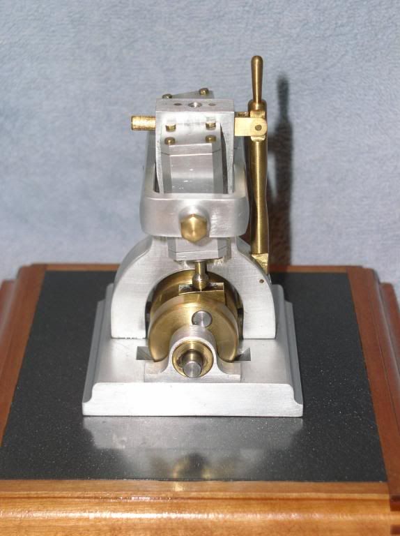
#58 I used a piece of 'hard brass' to make the valve 'lever' due to my concern that the turned handle on top might be on the weak side due to its small diameter. In the past I had difficulty clamping 1/8" and thinner work pieces that couldn't be supported with the 1/8" parallels that I have. So I when ordered my chuck back plates I added ultra thin 1/32" parallels that George Britnell recommended when I mentioned the problem that I was having, with clamping up thin parts in my mill vise. I'm glad I ordered this set as they seem to be a 'must have' when building these small engines.
Thanks George!

#59 Below is the set of ultra thin 1/32" parallels. I'm going to get a lot of use out of these due to their small 1/16" increments in height.

#60 After milling the 'lever' to 1/8" x 3/16" x 3", the slot for the 'levers' pivot pin was milled out using a 1/16" end mill. I shimmed the 'lever' on all four sides to keep from marring it in the 4" four jaw chuck, and dialed it in on center to turn the handle area using various angles on the small profile cutters on hand. After removing it from the chuck a couple of hand twists with emery paper was all that it needed.

#61 I cut up my last piece of wood to make the base, and the base for a single cylinder engine. Time to order some more wood since all that I have is 'left overs' that are to small for the size engines I like to build. All that's left is to finish up all the pieces with files and sand paper, a little paint and polish, and then on to the final assembly.

-MB
Thanks George!
#59 Below is the set of ultra thin 1/32" parallels. I'm going to get a lot of use out of these due to their small 1/16" increments in height.
#60 After milling the 'lever' to 1/8" x 3/16" x 3", the slot for the 'levers' pivot pin was milled out using a 1/16" end mill. I shimmed the 'lever' on all four sides to keep from marring it in the 4" four jaw chuck, and dialed it in on center to turn the handle area using various angles on the small profile cutters on hand. After removing it from the chuck a couple of hand twists with emery paper was all that it needed.
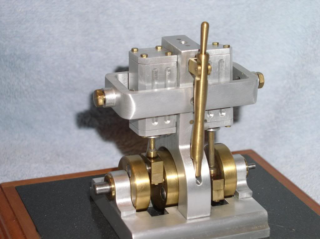
#61 I cut up my last piece of wood to make the base, and the base for a single cylinder engine. Time to order some more wood since all that I have is 'left overs' that are to small for the size engines I like to build. All that's left is to finish up all the pieces with files and sand paper, a little paint and polish, and then on to the final assembly.
-MB
- Joined
- Dec 28, 2008
- Messages
- 1,731
- Reaction score
- 9
1hand said:MB,
Are them 3" or 6" parallels? Your lever and Wooden base turned out perfect. Can't wait to hear it sing to us. Sounds like that isn't to far away.
Nice job as always, Matt
Matt, their 6" paralells. I didn't know they made 3". My vise is a 4", so the 6" hang out a bit. On the upside I keep dropping them and damaging the ends that stick out side the jaws,so it doesn't really matter.
Thanks, should be singing in a day or two. Running would be O.K. too! ;D
-MB
- Joined
- Dec 28, 2008
- Messages
- 1,731
- Reaction score
- 9
ksouers said:Moving right along there, MB!
How did you like using the 1/16 inch end mill? 2 or 4 flute?
The first time I used a 1/16" end mill I was tense to say the least more like petrified. I thought it was tiny. This time I got shook up halfway into the first cut thinking that it was too big to be the right size, I use a magnifier.
I used an inexpensive import from India, HSS, center cutting, four flute, double end, and 3/16' shank.
I go dead slow and cut .025" deep per pass in brass. On the valve lever five 3/8" long passes took about 30 seconds each. If I'm boxed in, like on a 'slide valve', I stick a straw in my mouth to clear the chips.
-MB
Similar threads
- Replies
- 83
- Views
- 17K