I forgot to mention one important step in making the valve seat cutting tool.. I used a diamond file and relieved each face by hand, leaving about .015 of land closest to the cutting edge untouched. This is a rather crude method of putting in the relief, but I have no other good way of doing it.
You are using an out of date browser. It may not display this or other websites correctly.
You should upgrade or use an alternative browser.
You should upgrade or use an alternative browser.
Brian builds Atkinson Engine
- Thread starter Brian Rupnow
- Start date

Help Support Home Model Engine Machinist Forum:
This site may earn a commission from merchant affiliate
links, including eBay, Amazon, and others.
Today I hope to make my valves. There is a nifty trick associated with making valves that Chuck Fellows told me about 2 years ago, but this is the first time I've actually tried it. Valve stems for these small engines are quite small in diameter, while the head is roughly 3 times as large. This means that I will be turning 1/2" drill rod down to 4mm diameter by about 1 1/2" long. When you do this with the material supported only in the chuck, the small diameter begins to deflect away fom the cutting tool, and you end up with a tapered valve stem, which is something you definitly do not want. The secret to avoiding this is to turn down only 1/3 of the total length at a time to just above finished size, beginning at the end farthest from the chuck. Record your dial reading or set your cross slide stops, then turn down the next 1/3, and finally the last 1/3 closest to the chuck. This works most excellently, as I proved to myself yesterday while making the valve seat cutting tool. Once all 3 sections are turned to about .001-.002" oversized, then use some emery paper supported by a flat hacksaw blade to dress the stem down to finished size, It is a good idea to have something with a 4mm bore in it to keep test fitting as you do this to ensure that you don't turn or emery the shaft to an undersized condition, which is as bad or worse than a taper.
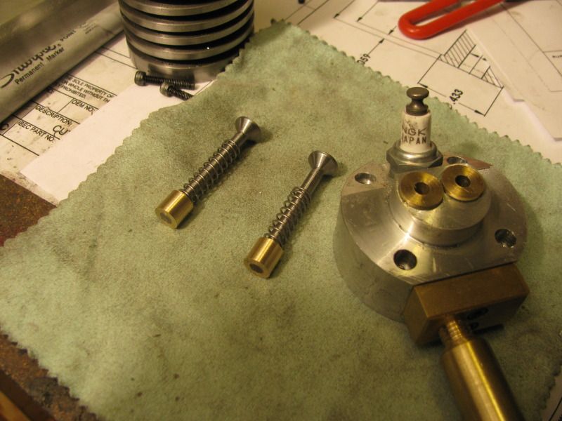
I just finished making the two valves from 01 drill rod. I selected a spring which I THINK may do the job, and turned a couple of valve spring keepers from brass. I will cross drill a 1/16" hole thru the brass keeper and the end of the valve and Loctite a 1/16" diameter cross pin into the hole to keep everything together. I have not lapped the valves into the cages yet, however it all fits together very well. In this picture you can also see the valve cages which have been lightly pressed and Loctited into the cylinder head.

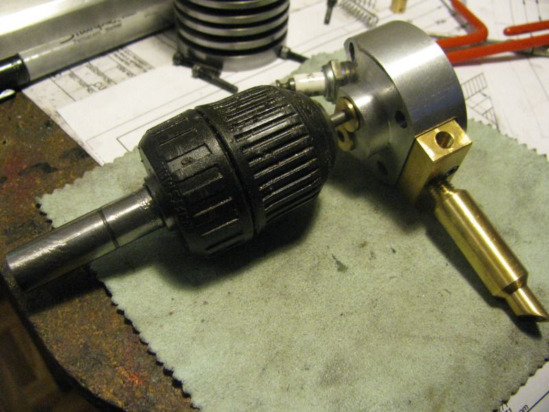
This is the way I lap the valves. I dab a bit of 350 grit carborundum paste, suspended in oil onto the face of the valve, being carefull not to get any on the stem. Insert the valve thru the valve cage, and grip the end of the stem with my little chuck. Then work it back and forth as many times as you can before your arms get too tired, About every 10 times back and forth, shove the valve in as far as the chuck allows and then pull it tight again so the valve face is in contact with the seat in the cage, this "recharges" the grit between the faces being lapped by pulling some in from around the edges. Once this process has began, the valves become dedicated to whatever seat they were lapped in and shouldn't be mixed up afterward. I am probably a bit paranoid about this, but I have 350 grit, 400 grit, and 600 grit, and will repeat this process with each of them, beginning with the 350 and ending up with the 600. The valve and the cylinder head should be washed thoroughly with varsol or paint thinners every time that you change grit sizes, and again when you are finished. DO NOT DO THIS WITH A POWER TOOL. THAT WILL RUIN BOTH THE VALVE AND THE CAGE!!!
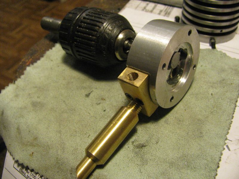


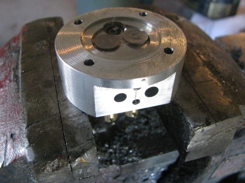
Well, I just MIGHT break out into my Happy Dance!!!! This afternoon after I was finished lapping the valves, I set the head up in my mill vice and drilled the ports thru the sides of the Loctited valve cages. I assembled the valves, springs, and keeper plates and torqued down the spark plug. The head has been setting in my old garage vice for an hour now, filled with paint thinner, and nothing is dripping from the ports or down the valve stems.


$19.15
$29.95
Competition Engine Building: Advanced Engine Design and Assembly Techniques (Pro Series)
MBC Inc.
![DreamPlan Home Design and Landscaping Software Free for Windows [PC Download]](https://m.media-amazon.com/images/I/51kvZH2dVLL._SL500_.jpg)
$0.00
DreamPlan Home Design and Landscaping Software Free for Windows [PC Download]
Amazon.com Services LLC

$599.00
$649.00
FoxAlien Masuter Pro CNC Router Machine, Upgraded 3-Axis Engraving All-Metal Milling Machine for Wood Acrylic MDF Nylon Carving Cutting
FoxAlien Official

$26.89
$34.99
Peachtree Woodworking Supply Bowl Sander Tool Kit w/Dual Bearing Head & Hardwood Handle, 42 Pieces Wood Sander Set, 2 Hook & Loop Sanding Disc Sandpaper Assortment, 1/4 Mandrel Bowl Sander
Peachtree Woodworking Supply Inc

$37.38
$49.99
Becker CAD 12 3D - professional CAD software for 2D + 3D design and modelling - for 3 PCs - 100% compatible with AutoCAD
momox Shop

$45.99
Sunnytech Mini Hot Air Stirling Engine Motor Model Educational Toy Kits Electricity HA001
stirlingtechonline

$49.95
$55.99
DjuiinoStar Hot Air Stirling Engine Assembly Kit: Spend 30 Minutes to Build Your Own Stirling Engine
djuiinostar

$99.99
AHS Outdoor Wood Boiler Yearly Maintenance Kit with Water Treatment - ProTech 300 & Test Kit
Alternative Heating & Supplies
- Joined
- Mar 13, 2012
- Messages
- 583
- Reaction score
- 62
Well, I just MIGHT break out into my Happy Dance!!!!
Well, I certainly hope so, but if you do we want to see a video! Rof}
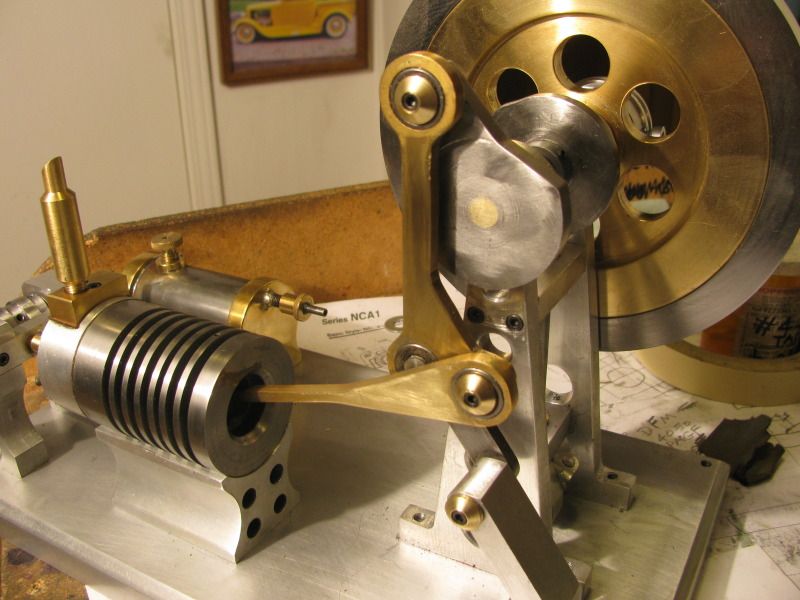
This mornings work consisted of making a head gasket and intake manifold gasket and installing them, machining 3 bearing retainers, and making the stubby little valve push rods that ride in guides between the cams and the head of the valves. I got a bit fancy with the bearing retainers, and made them cone shaped as opposed to a flat brass plate. The engine has good compression and will "kick back" when I try to spin the flywheel by hand. The cams do open the valves as they are supposed to, and I left .005 to .010" clearance between the end of the push rods and the face of the cams (when they are not up on the lobed section) to make sure the valves are not inadvertantly held open.

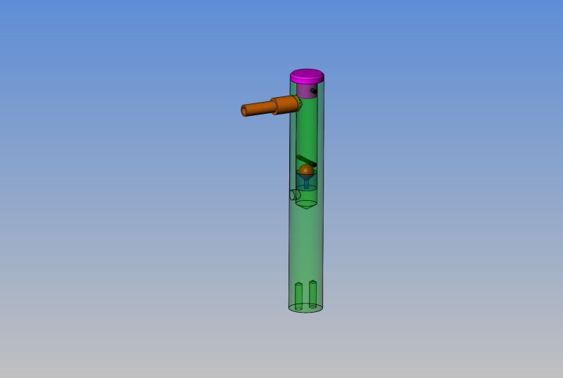
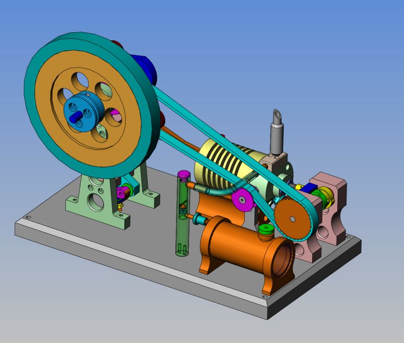
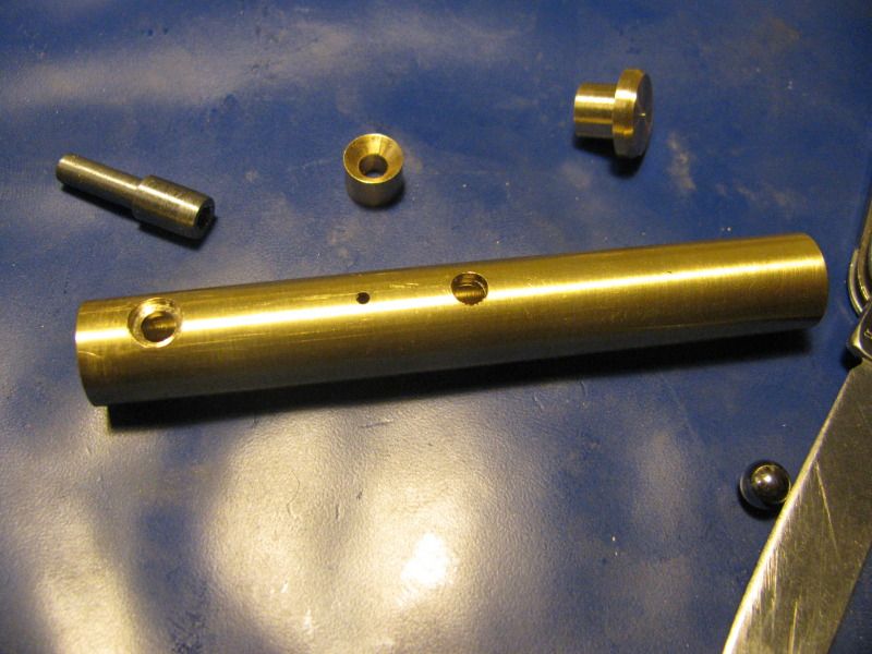
This whole concept of an engine backfire on start up causing a backwash of flame into the "vapour petrol tank" and consequently a flaming explosion has me a bit freaked!! Jan Ridders sent me a copy of what he recomends, but it doesn't quite fit the concept of what I want things to look like. I have designed my own, which is primarily made of brass with a 3/16" steel bearing check ball setting in a coned seat. i have never heard of such an explosion happening, but I don't want to be the first. I have attached a transparent model of what my valve would look like, and where it would set on the completed model. It bolts to the main base from underneath, and is sealed to the outlet of the tank with a bit of epoxy.---Remember, we are only working with gasoline vapour here, not liquid gasoline.


This morning I got up and went to see a clock repair man at a local mall. Its a little one man shop, and the gentleman there is from somewhere in Europe. I explained to him that I was looking for a glass lens to fit the end of the gas tank, which I had taken with me. This lead to a discussion about model engines, how I make them, etcetera. The upshot of it all was that he went into a back room and came out with the perfect size lens, and when I asked "How much"? his reply was that he would love to come visit my shop and see some of the 14 or 15 models I have built, and "No charge" for the lens.----I love it!!! I gave him one of my business cards and invited him to "Come any time, for a visit." This afternoon I ran all over Barrie with good wife looking for the perfect chair to compliment a newly decorated bedroom, then carved out all the parts for my check valve for the vapour fuel tank when that rodeo was over.
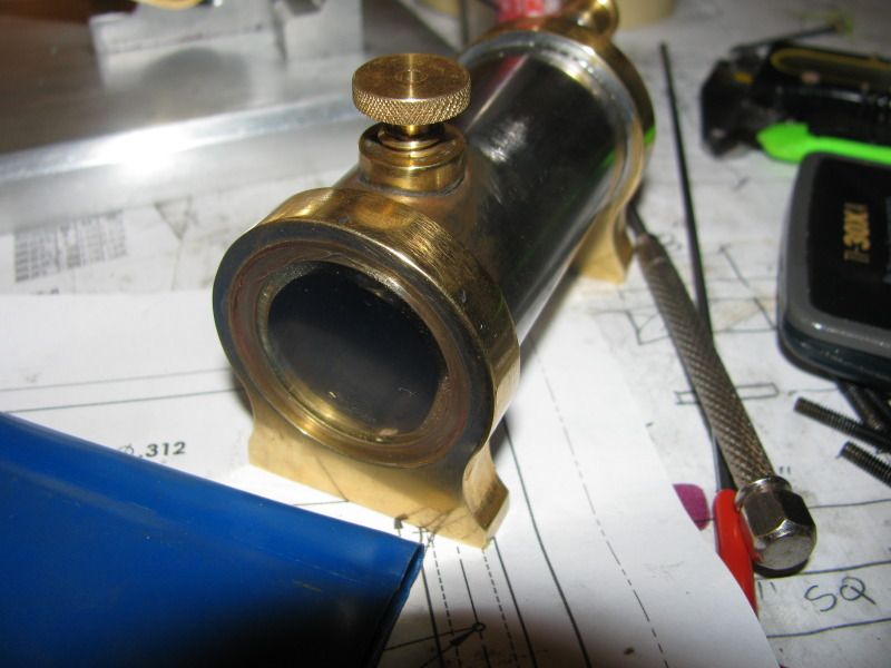


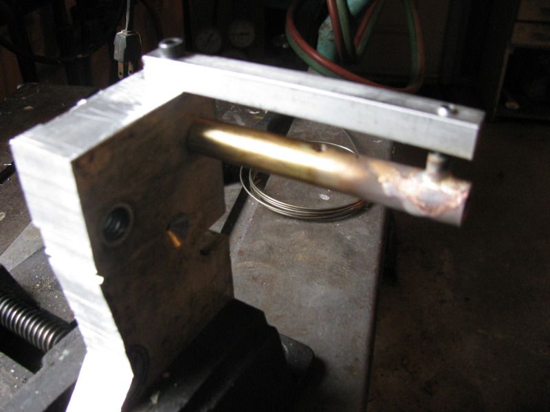
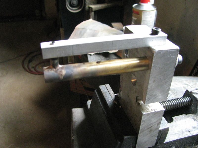
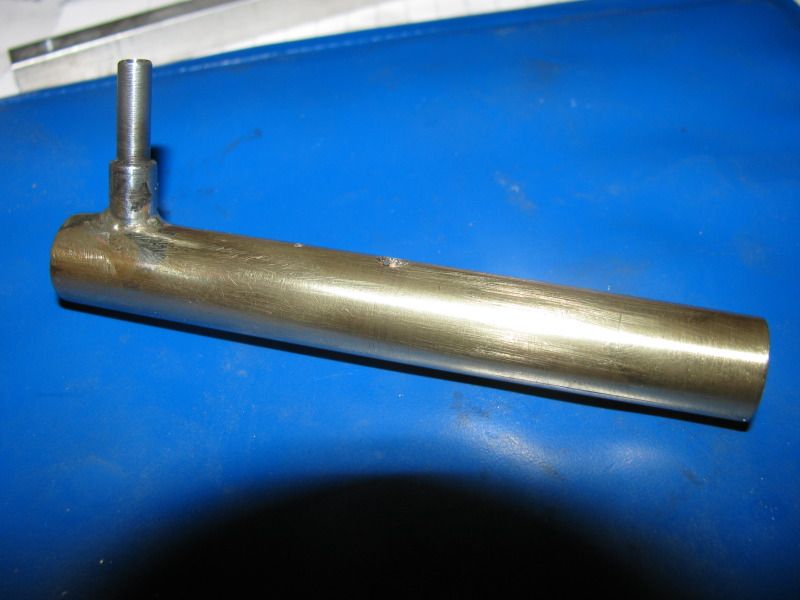
A quick and dirty jig built from scrap bits of aluminum esures that the outlet tube will be square and true to the main valve housing while I silver solder it in place. Experience has taught me over the years that no matter how well I position two peices for soldering, one of them always moves during the soldering process. A jig made from scrap bits holds everything steady and yields far more professional looking results.
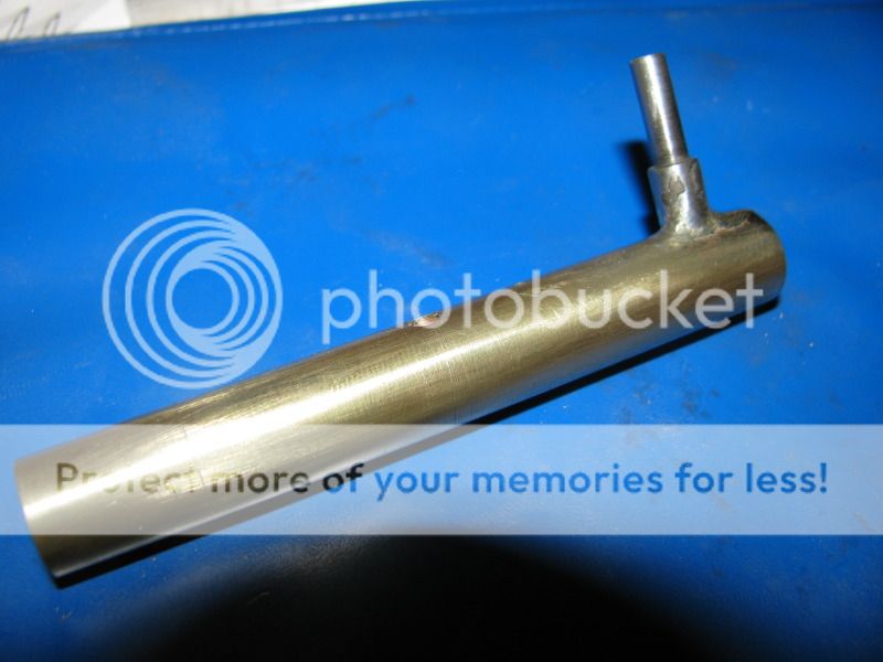


Clever design. Simple, yet functional. And, it looks good to. 
Todd
Todd
Well boys and girls---Thats as good as it gets!!! The check valve works good as tested by putting the discharge end in my mouth and finding that yes, I can suck but no, I can't blow!!! No nasty comments from the peanut gallery. I can't do any more now untill my drive belt and pulleys get here. I have been notified that they are "In the mail"-----Somewhere.
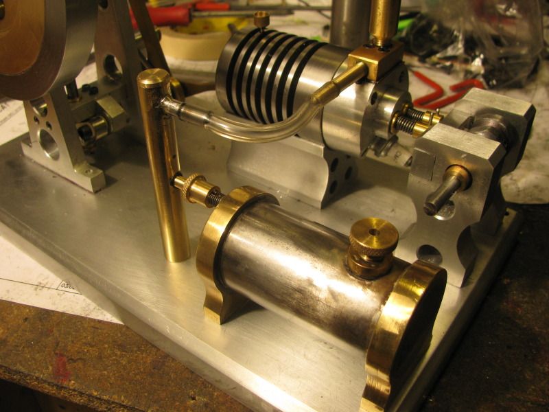
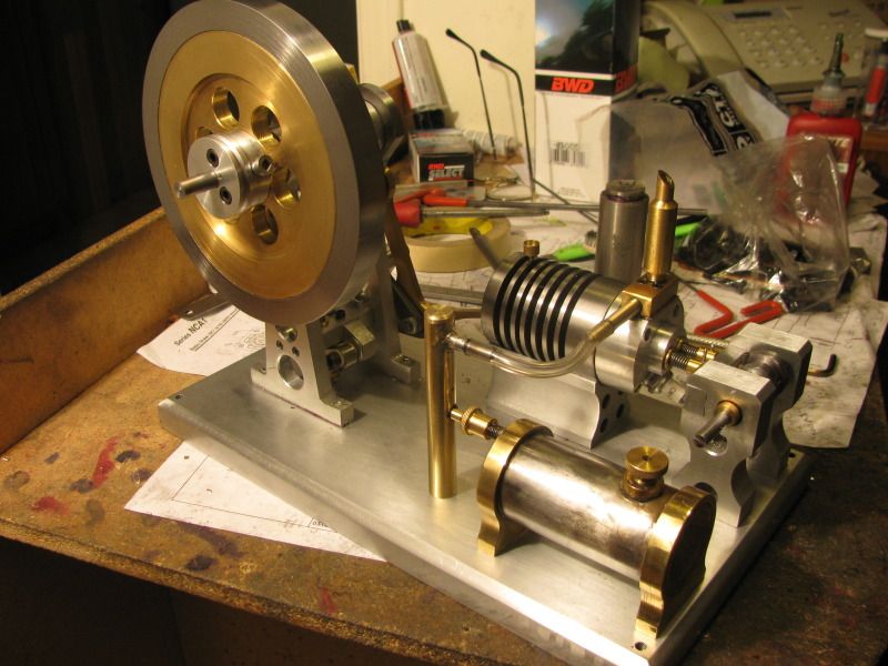


I hope that some of the 20,000 people who have had a look at this long thread have enjoyed it. I hope that some may have learned something from it. One of the things I have noticed about projects that go on for a long time---People don't stop looking, but they quit responding to the posts. The engine is almost done now. All of the parts are finished, except for the pulleys and belt. I have to build a box with a switch and 12 volt coil in it. However, it will not be dedicated solely to the Atkinson engine. I will use it for my Webster engine, and any future i.c. builds that I get involved in. Although this project only started in early July, I feel as if its gone on for much longer. It has helped put in the summer, and each time I build something like this, I learn more myself. If the model engine Gods smile on me, we may even have a runner by the end of next week.----Thanks for looking.---Brian
- Joined
- Jan 19, 2010
- Messages
- 1,193
- Reaction score
- 41
Brian, I am one of those who has been watching every step of the way and excitedly view all new postings, but I have not posted. In fact, this is my first post on the new forum. My new job (Which I LOVE! btw) has been taking up all my time, if I am not at work, I am at home, thinking about work, and has left me unable to post as frequently as I used to. This is the longest I have gone without posting.
This is a fine model you have chosen to build, and your work on it is outstanding. I can't wait to click on the video of its first pops.
Kel
This is a fine model you have chosen to build, and your work on it is outstanding. I can't wait to click on the video of its first pops.
Kel
Well, I for one, can't wait to see and hear it running. It's been a real treat to follow along and learn from your techniques. I've got some mods to do to my mill this weekend. And after that, I hope to put some of the knowledge I've gained from everyone here on the forum to good use. Not sure what simple little engine I'll try first, but it's gonna be fun. 
Todd
Todd
Thanks for saying Hi, guys. It always pleases me when I hear from folks during my build process. It keeps my flame burning!!! I have been wondering as I built this engine about the fact that Jan Ridder doesn't show any rings on his piston. I went back over the literature yesterday afternoon, and checked out Jans build and the builds done by a few other people which he gives links to. Most of the people who built this engine put some form of rings on it, although Jan does state that the engine doesn't need any rings "IF THE PISTON TO CYLINDER FIT IS VERY GOOD!!! " Now, on my engine, that fit is very good and my engine does have great compression. However---I wear a belt and suspenders.---So, wanting to be prepared in case I did need rings, I did a little detective work. When I built the engine, I used a 7/8" reamer to finish the cylinder. That lead me to believe I must have built some other engine with the same 7/8" bore in order to have purchased that reamer in the first place. ---Sure enough, the Webster I built has the same bore. At the time I built the Webster, I posted all the information about the ring diameter, part number, groove diameter, etcetera!!! This is a great discovery, ----If I need more compression than I currently have, i have all the info right at my fingertips.---Brian
http://www.homemodelenginemachinist.com/f31/anybody-want-guess-7687/
http://www.homemodelenginemachinist.com/f31/anybody-want-guess-7687/
Brian,
I have been watching and following your project. I really want to thank you for all your time on posting so many details and information. I wish I could have your energy to get things done. I have learn a lot here with your post and would like to ask you so many questions but will be taking more time out of you and you have already given a lot to all of as.
Looking forward to see that engine working.
Mario
Similar threads
- Replies
- 11
- Views
- 770
- Replies
- 11
- Views
- 1K
- Replies
- 413
- Views
- 68K
- Replies
- 28
- Views
- 3K


![MeshMagic 3D Free 3D Modeling Software [Download]](https://m.media-amazon.com/images/I/B1U+p8ewjGS._SL500_.png)


