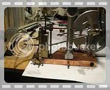
Beam engine at double scale--

Home Model Engine Machinist Forum

Help Support Home Model Engine Machinist Forum:

This site may earn a commission from merchant affiliate links, including eBay, Amazon, and others.
So---Today we built the valve. I'm not particularly proud of this work, because while trying (and trying, and trying) to achieve a "perfect" fit into the brass cylinder, I resorted to doing some final dressing of the diameters with a light file (my tooling is carbide, and not much good for taking off realy small finish cuts). And darned if I didn't hold the file on a bit of an angle ---you can just see it on the inside end of the small diameter farthest from the cross hole. It ended up tapered a bit, and I don't know how this is going to affect the running of the engine. I do know that I have about 6 friggin hours in making the valve, and unless it out and out keeps the engine from working, I'm not making another one!!! (This was machined from a 5/8" diameter cold rolled shaft, because thats what I had.) I was going to buy some brass, as the drawing calls for, but since the cylinder is brass, I thought it might be wise to use a different metal for the valve.---Brian

VALVE002 (Large).JPG
 
This afternoon I made up an air inlet tube and a plug for the back of the cylinder where I had to drill thru from the opposite side to punch out a small (2 mm) diameter drill that I broke off when drilling thru the steam ports on the cylinder. I silver soldered them into place, and although it looks a bit ratty, the soldered areas should clean up good when it comes time to polish the cylinder with my buffing wheels and compound. I will put up a drawing of the inlet port either later today or first thing tomorrow morning.

INLET TUBE AND HOLE PLUGGING001 (Large).JPG


INLET TUBE AND HOLE PLUGGING003 (Small) (Large).JPG
 
When I made that valve, albeit on the print scale version of this engine, I simply turned a length of rod to the requisite diameter, sliced off two chunks, faced and drilled them to the size of the valve rod, then soldered them into place. Much easier than trying to turn a long, slender part like that from a single piece of stock.

It's often true, especially so for small models, that a fabrication is far easier to make than carving the part from the solid. In fact, learning when and how to fabricate is one of the more difficult tasks for novice modelmakers.

Kozo Hiraoka is the acknowledged expert in this discipline. Even if you're not interested in building a live steam locomotive, search out and read his books just for the ingenious methods he uses to fabricate complex parts.
 
mklotz said:
When I made that valve, albeit on the print scale version of this engine, I simply turned a length of rod to the requisite diameter, sliced off two chunks, faced and drilled them to the size of the valve rod, then soldered them into place. Much easier than trying to turn a long, slender part like that from a single piece of stock.

It's often true, especially so for small models, that a fabrication is far easier to make than carving the part from the solid. In fact, learning when and how to fabricate is one of the more difficult tasks for novice modelmakers.

Kozo Hiraoka is the acknowledged expert in this discipline. Even if you're not interested in building a live steam locomotive, search out and read his books just for the ingenious methods he uses to fabricate complex parts.
Thanks Mklotz---You're absolutely right. I never even thought of that.---Brian
 
Looking good Brian.

I have been off my version for several weeks now. I had a major power hit that wiped out much of my electronic junk, including the shop computer. It seems that the power company substation down the hill caught fire about three weeks ago. All sorts of voltage transients as their circuit breakers opened, arcing in the substation and rerouting relays kicking in. Two new hard drives and one DVD drive later and a lot of sweat later everything is back to normal. One of the hard drives was my primary and the other was my backup mirror. Fortunately I was able to recover most everything from the drives and I have a USB external drive that is a secondary backup and gets updated twice a month. It had the rest of the stuff on it. This is just to remind everyone to keep good backups.

In the meantime, I finished up a couple of other projects so they are out of the way. There is still one other project that I need to finish up and the parts for it should be here tomarrow.

I have the cylinder group completed and some of the linkage parts underway. Flywheel and eccentric parts are complete and the base has been saw cut to rough shape and ready to machine. Still, there will be no way to catch up with you. You are too quick for me.

Gail in NM,USA
 
Looking good to me Brian, and it's all right you take your time no matter what they say :eek: :big:
Fair do's you don't hang around.... I would say I can't wait for the finished article again, but you'll probably be posting that in a week!! ;D

Bad news if the valve is a no go.... I have a few bits in 'stock' like that!


Looking forward to the rest,


Ralph.
 
The engine is setting behind my chair on the floor, being "run in" by the 3/8" drill motor. This gets rid of all the tight spots and binds that are always present on a new motor.---and before you ask, that masking tape is wound around both ends of the drill which I an still using for one of my pivot pins to keep it from falling out. All I have left to do is machine the straps that run from the valve actuator lever arms up to the top of the valve. I will do that now, and sometime today I have to buy some more silver solder. We might see this thing run under its own power today!!!

ENGINE RUNNING IN001 (Large).JPG
 
Well, for the moment I seem to be snookered!!! I finished making the straps that run from the valve actuator rod up to the valve itself, and found some 1/8" cold rolled shafting to connect everything---then found out that I am completely out of silver solder. I dummied everything into place anyway and thought-AhaH!! This thing should run now.---And thats what I've been trying to do for the last 3 hours. Oh, it wants to run--sometimes it turns over 2 or 3 times before it quits.--I tried every imaginable air pressure and checked that center to center of all my links were the correct length. I even added a temporary much heavier flywheel. I played with the position of the eccentric untill I had covered all 360 degrees of possible settings, I am sure, but no dice.!!! In trying to do some diagnostics, I find that the piston rod has a lot of power when extending outward from the cylinder, but is rather wimpy when retracting into the cylinder---That plus the fact that I am losing a large quantity of air out the top hole of the cylinder cap where the valve passes thru. This leads me to believe that I got such a poor fit between the valve and the cylinder bore that the air which should be pushing my piston is escaping past the valve and peeing away into the atmosphere.

VALVE LINK STRAPS001 (Large).JPG
 
Okay---Valve, second time around. I couldn't get the engine to run, and I assume its because my valve was too much undersize for the bore it fit in the cylinder, and I was losing a lot of air to atmosphere. I had reamed that cylinder with a 1/4" straight flute reamer, and when I tried a peice of 1/4" cold rolled rod in the hole it seemed to be a perfect fit. So---I chucked it up in the lathe, turned the reduced diameter closest to the valve bottom (the recessed area closest to the pivot doesn't really serve any purpose). I then cut the rectangular end off the original valve, with about 5/8" of the round shank, put a 1/8" dia. c'bore in the end of the new valve, and glued them together with Loctite 638.---Now we try again---

VALVE---SECOND TRY002 (Large).JPG
 
Brian,
The recess at the top end is necessary to exhaust the upper end of the cylinder.
Gail in NM,USA
 
Gail---I just figured that out. I put it back together, and it isn't loosing air anywheres near as much, but it wouldn't "kick" either. I am machining it right now.---Brian
 
Congratulations Brian.
Feels great when they first run. After that it's just details.
Gail in NM,USA

 
Nice work Brian, congratulations on a good looking runner. :bow: You've kept a lot of us interested in your progress along the way and it's nice to see the finished product.

Cheers,
Phil
 
Congrats on it being a runner Brian!

Looks Great!

I've enjoyed your well documented build here.
Looking forward to the next one.

Rick
 
Here is a much better video of the beam engine running. It missed some of the audio right at the beginning, but it does give a much better look at the engine.
 
That's a great runner, Brian! She's a beauty.

Congratulations! :bow:

Nice video and well documented project.
 
Nice Brian... Very nice ;D

A bit of bling and you got yourself a nice show piece ;)

Are we going to get another vid once shiny as well as some photo's?

(see it just goes to show you "if you build it they will come" :big: )

Thanks for taking the effort.... My turn soon.... When I get my busy a@% back in the shop!! (winter soon... = more shop time :D )


Looking forward to the finished article :)


Ralph.
 
Brian Rupnow said:
Well Guys---Its sitting here on the corner of my desk running.

Yee Haaaaaaaa!!!

Way to go, Brian! :bow: :bow: :bow:

Kludge


Latest posts

Back
Top