I seem to have worked my way through the greatest part of the pain, with the help of physiotherapy, Oxycodone, and time. I am still feeling a bit fragile around the base of my spine, but at least I've quit hurting. I really don't know what caused this flare up of Sciatica, but it was either using a different computer chair, or standing too long at my lathe. Whatever it was, thank God it's gone. I am not going to be machining anything until at least mid October, because I want to make sure this is totally cleared up before I do anything that might cause it to come back. In the meantime I will take all of the solid models I downloaded them from Grabcad and convert them to 2D dimensioned drawings so I will have something to work from when I do start machining again.---Brian
You are using an out of date browser. It may not display this or other websites correctly.
You should upgrade or use an alternative browser.
You should upgrade or use an alternative browser.
Back to Steam
- Thread starter Brian Rupnow
- Start date

Help Support Home Model Engine Machinist Forum:
This site may earn a commission from merchant affiliate
links, including eBay, Amazon, and others.
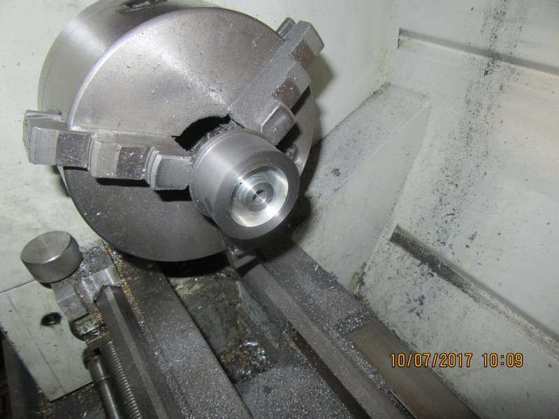
I couldn't stand being idle any longer, so--This morning I turned the final outside diameter on that short end of cast iron that was in my lathe, faced the outer face, and bored it for a "push fit" of the aluminum center into it. Coated the outside of the aluminum center with 638 Loctite, and pushed it into place. (a "push fit" is half way between "get the hammer fit" and "Oh damn, it falls through fit").

- Joined
- Dec 12, 2012
- Messages
- 2,220
- Reaction score
- 1,288
Its the one fit hardest to achieve. Its either the hammer or the fall thru
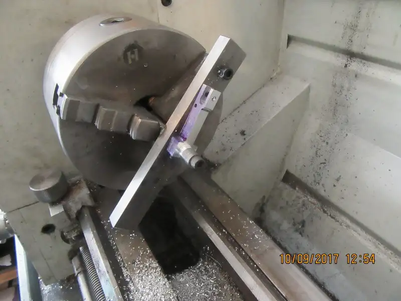
My, but there is a world of set-up work in these con rods. By the time I'm done with two of these things, I'll be qualified to start machining ear-rings for my wife!!

stragenmitsuko
Well-Known Member
- Joined
- Jan 19, 2016
- Messages
- 327
- Reaction score
- 143
(a "push fit" is half way between "get the hammer fit" and "Oh damn, it falls through fit").
I love it
- Joined
- Dec 12, 2012
- Messages
- 2,220
- Reaction score
- 1,288
With ref to these comments and the thread on micrometer readings
I normally work to 1 thou.However i have just finished the silver steel
crankpins on the Simplex and wanted to achieve a medium press fit,whatever that is
Too tight and might crack the casting. Too loose and its a fall back to loctite
Long story short the reamed holes were oversize so checked with a carbide endmill shank which was 5 tenths down.After turning a no of samples a good
running fit was +1 thou so i first aimed for +1.5 then 2 etc. When i got what i wanted i allowed +- 5 tenths.Worked well but labour intensive
![DreamPlan Home Design and Landscaping Software Free for Windows [PC Download]](https://m.media-amazon.com/images/I/51kvZH2dVLL._SL500_.jpg)
$0.00
DreamPlan Home Design and Landscaping Software Free for Windows [PC Download]
Amazon.com Services LLC

$99.99
AHS Outdoor Wood Boiler Yearly Maintenance Kit with Water Treatment - ProTech 300 & Test Kit
Alternative Heating & Supplies

$104.99
Sunnytech Hot Air Stirling Engine Motor Steam Heat Education Model Toy Kit M16-CF
stirlingtechonline

$40.02
$49.99
Becker CAD 12 3D - professional CAD software for 2D + 3D design and modelling - for 3 PCs - 100% compatible with AutoCAD
momox Shop

$26.89
$34.99
Peachtree Woodworking Supply Bowl Sander Tool Kit w/Dual Bearing Head & Hardwood Handle, 42 Pieces Wood Sander Set, 2 Hook & Loop Sanding Disc Sandpaper Assortment, 1/4 Mandrel Bowl Sander
Peachtree Woodworking Supply Inc

$599.00
$649.00
FoxAlien Masuter Pro CNC Router Machine, Upgraded 3-Axis Engraving All-Metal Milling Machine for Wood Acrylic MDF Nylon Carving Cutting
FoxAlien Official

$171.00
$190.00
Genmitsu CNC 3018-PRO Router Kit GRBL Control 3 Axis Plastic Acrylic PCB PVC Wood Carving Milling Engraving Machine, XYZ Working Area 300x180x45mm
SainSmart Official
That is why I default to reamers for my assembly fitting. They pretty well hit the tolerance limits "right on", and save me a lot of time and frustration.
Its the one fit hardest to achieve. Its either the hammer or the fall thru
Baz,
If you do get the 'fall through' don't forget your knurling head.
Just a very very light straight knurl on a part can easily make your piece part grow by 0.002", so saving having to make a new piece.
I like this method anyway as it gets the Loctite right down into the joint making it, to me, a lot more secure, having both mechanical and chemical jointing.
John
- Joined
- Dec 12, 2012
- Messages
- 2,220
- Reaction score
- 1,288
I have tight spots on the wheels of the simplex so lots of playing about with not a lot to show for it.A light press fit means i can easily get them off and fall
back to knurl/locktite. Wish i had lots of reamers Brian but all have is few worn
imperial, some cheap chinese metric or homemade D bits. I wish
back to knurl/locktite. Wish i had lots of reamers Brian but all have is few worn
imperial, some cheap chinese metric or homemade D bits. I wish
Bazmak--That is why I still work 3 days a week, designing machinery for a company here in town. That gives me enough "cushion" that I can go out and buy whatever tooling I need without dipping into "pension money". Well, that's part of the reason anyways. Truth be told, if I didn't have something to do besides machine my hobby projects, I'd go nuts. The work I do isn't physically demanding, and I love doing it.
vederstein
Must do dumb things....
- Joined
- Feb 26, 2011
- Messages
- 932
- Reaction score
- 776
Brian,
What size of lathe do you have? That picture makes your con-rod look huge, but you said the engine was tiny. I'm trying to get a sense of scale.
Thanks,
...Ved.
What size of lathe do you have? That picture makes your con-rod look huge, but you said the engine was tiny. I'm trying to get a sense of scale.
Thanks,
...Ved.
The full length of that con rod including the bolt on end-cap is 2.3" long. The lathe chuck is 6" diameter,
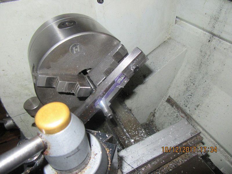
I'm now into "second set-up" with the con-rods, machining the other side. Same fixture, but with a spacer washer of appropriate thickness between the finished big end boss and the fixture. The fixture is very handy for this kind of work. I know it doesn't look terribly different from the previous picture. After this operation is performed on both rods, then I have only to round the small ends and do a little "clean up" with my jewellers files.

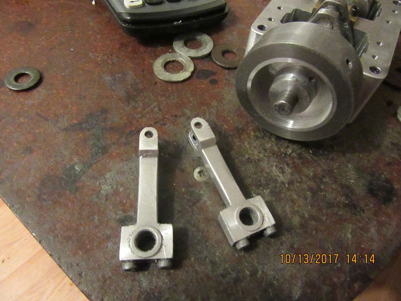
Today I finished the con rods. They turned out quite well. No, it isn't your eyes, that gudgeon pin hole in one of the rods is off center a bit. It won't affect how the con rod works, and if it is hugely visible when everything is assembled, I may make a replacement. It has burned about 8 hours of my time making these two.

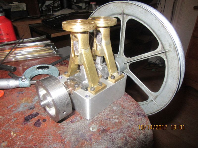
Okay--I have to say it--I'm stoked!!! It has been a long and busy day, but the first stage of assembly has been a great success. I completed the cross heads and "dummied up" a set of cross pins to connect the cross-heads to the connecting rods. I completed the bottom ends of the cylinders, with an integrated "guide/seal" on the underside to guide and seal the piston rod. Everything rotates and clears everything else. The engine is still a bit stiff, that is why the big V pulley is there. It lets me rotate the engine carefully and slowly by hand to check for clearance issues. The little 2" flywheel doesn't give me enough mechanical advantage to do this comfortably. Tomorrow, I will machine the pistons and piston rods, and try to get a video up showing the operation of the assembled parts so far.

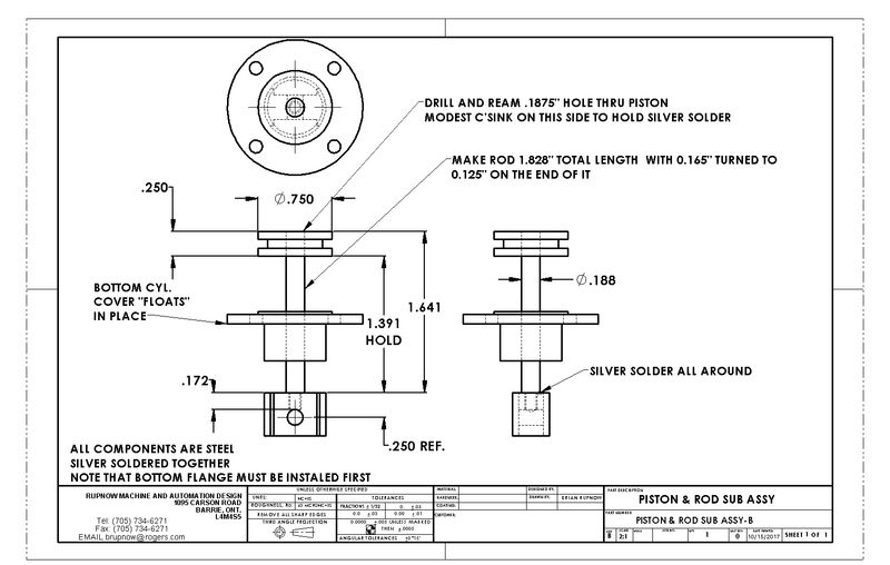
Today we're going to change things up a bit from the original Stuart engine. The piston will have one 1/16" diameter Viton o-ring. The piston rod is going to increase from 0.156" dia. up to .188" diameter (because I have a ton of 3/16" cold rolled), and there will be no threads at either end. The piston rod will be fitted into reamed holes in both piston and cross head and silver soldered in place. Of course this means that the bottom cylinder cover must be finished and placed on the piston rod before the ends are soldered in place, as it can not be installed afterwards.

Mechanicboy
Well-Known Member
- Joined
- Jul 10, 2013
- Messages
- 959
- Reaction score
- 349
The piston rod will be fitted into reamed holes in both piston and cross head and silver soldered in place. Of course this means that the bottom cylinder cover must be finished and placed on the piston rod before the ends are soldered in place, as it can not be installed afterwards.

In my Stuart D10 the piston is fixed to piston rod while the piston rod is screwed to cross head. It will be practical to unscrew the piston rod from cross head when it is need to replace the worned O-ring with a new O-ring when the cylinder head is dismantled.
A question: No cland box gasked in the bottom cover?
The brass/bronze (bottom cover) will expand more than the steel (piston rod) who lead to more leakage. In my Stuart D10 the cland box is packed with graphite yarn who last very long time. O-ring as gasked in gland box works well too.
I find that I have trouble with alignment on parts assembled with small diameter short threads. A reamed hole ensures my alignment. There is no gland nut on the bottom of the cylinder plate, as this engine will be ran on compressed air, not steam. A reamed fit and a bit of oil gives all the sealing required. There will be no heat, so I'm not worried about differential expansion factors.---Brian
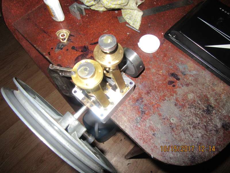
As I promised, here is a YouTube video of the engine to date, and a top view, showing the soldered piston to piston rod connection. I noticed after watching the video that I called the pistons --cylinders, so be forewarned.
[ame]https://www.youtube.com/watch?v=9_35ADjGqSM[/ame]
[ame]https://www.youtube.com/watch?v=9_35ADjGqSM[/ame]

Similar threads
- Replies
- 13
- Views
- 798
- Replies
- 8
- Views
- 1K
- Replies
- 0
- Views
- 944


![Learning AutoCAD Civil 3D 2014 [Online Code]](https://m.media-amazon.com/images/I/51F3yi9fokL._SL500_.jpg)


