anyone interested in a radial team buid

Home Model Engine Machinist Forum

Help Support Home Model Engine Machinist Forum:

This site may earn a commission from merchant affiliate links, including eBay, Amazon, and others.
Hey Path,

I need to get that crankcase drawing from you did you send it this week end. I am in the shop atm and can start working on them if I can get another copy of it. I looked this morning and there was nothing there let me know which address that you are sending it to I may be looking at the wrong email.

That you for your time in this matter.

Dan tanner
 
ordered the domenuts needed for the engine today. still waiting on my brass for the tag.
Pascal
 
DTANNER said:
I need to get that crankcase drawing from you did you send it this week end. I am in the shop atm and can start working on them if I can get another copy of it. I looked this morning and there was nothing there let me know which address that you are sending it to I may be looking at the wrong email.

Dan tanner

Dan ...

I've been sending them to [email protected] as requested in your email dated 9/18/11.
So far you should have 4 emails dated 9/18/11, 9/20/11, 9/20/11 and 10/13/11.

If you can't find them let me know I'll be glad to resend them ...


Pat


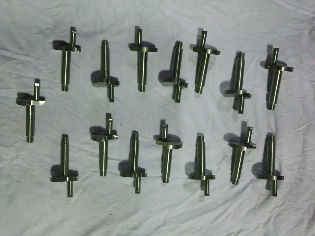
Crank shafts done plus a few extra's.

Pottycranks.jpg
 
they look pretty good..

Im just waiting for one more address then ill pm you all the list.

 
Warranator,

Really looks nice! :bow: :bow:

Have any pictures or action on the return crank?


Pat
 
Will post a video next week of the return crank being machined.

I have question: Does the return crank and the crank line up when they fit together? Are the 2 shafts 4.17mm (return crank) and the 9.525mm (main crank shaft) supposed to be in line with each other when put together? If they are supposed to line up then I need to adjust the part so they match up as I don't think they do, I only looked by eye but it looks out.
 
The main crank drives the return crank, the position of the flats on the main crank and the little drive pin on the return crank is important as this governs the timing of the engine, the drive pin is slightly off set, this is shown on my drawings.

Stew

 
Sorry realised I put 4.17 instead of 7.17mm in previous post.

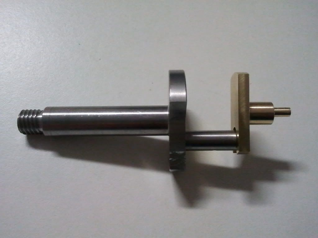
Ok.....I understand how critical the position of the slot and the little drive pin are on the return crank and they are spot on. What I am asking is: The centre line between the 2 shafts 7.17mm (return crank) and the 9.525mm (main crank), must they be in line? Not sure if you can see in the pick but they don't seem to be in line.

2011-10-21183708.jpg
 
warranator said:
I have question: Does the return crank and the crank line up when they fit together? Are the 2 shafts 4.17mm (return crank) and the 9.525mm (main crank shaft) supposed to be in line with each other when put together? If they are supposed to line up then I need to adjust the part so they match up as I don't think they do, I only looked by eye but it looks out.

Warranator,

I hope you are referring to the 7.14mm dimension (instead of 4.17mm, which I can't find)! ;D

There is an interference issue with the Return Crank Slot and the Crank.

See post #136. Repeated here:

The Crank ...
It doesn't line up with the Return Crank slot. Just a tad lower ... maybe not a big deal if all other parts are right on ... but if not built in our favor it might have to be slimmed down at the slot. We'll see.


When the rest of the assembly is assembled the Center Line of the Crank (bearing shaft) and the Return Crank Shaft (7.14mm) will be in line.

The issue is that the slotted shaft (6.35mm) will not seat in the Return Crank slot. That because the Center Line offset is not quite enough.
How much interference will depend on all the other actual center lines.

My thought on the solution is to leave your parts as is and let the team fix the issue themselves since they will know exactly how much material needs to be removed at the flat end of the Crank Shaft. I would use a 4 jaw chuck and turn it down until it fit ... but not disturbing the flats.


Now a question for you ...

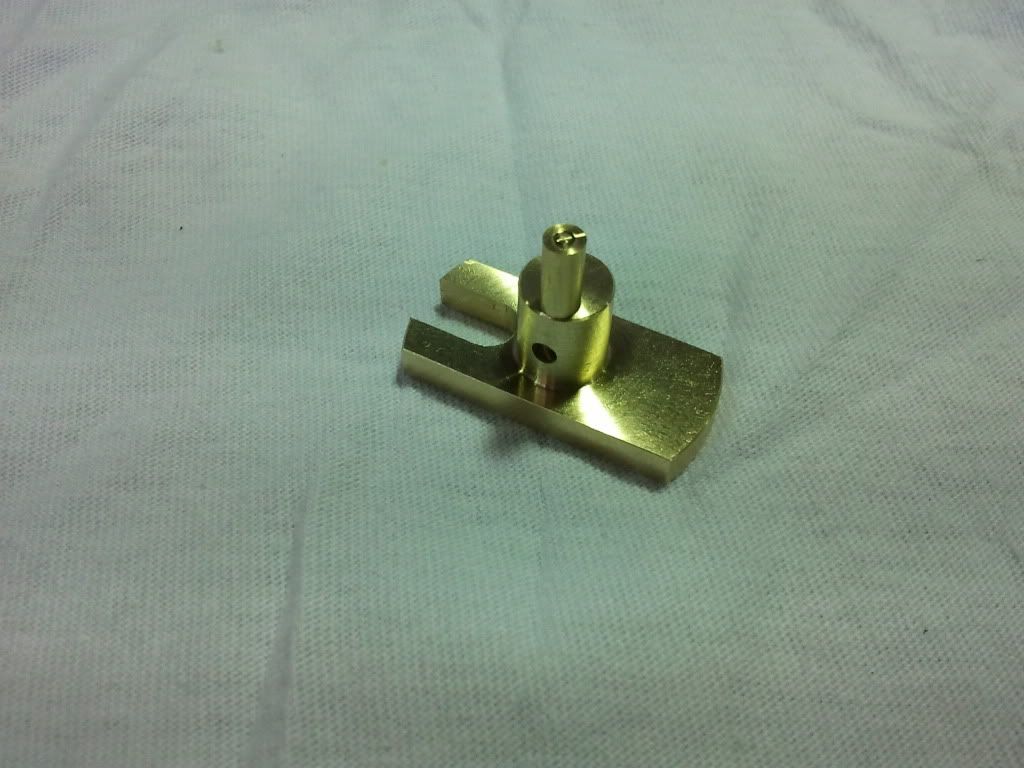
In the picture of the Return Crank ... it looks like the bottom of the slot is not at the perimeter of the 7.14mm shaft ... or is it?


It's late .. I hope I have answered your question .. if not I can go into more detail tomorrow.


Pat H.
 
No the slot is not at the perimeter of the 7.14 slot. This is what I was wondering. I could modify the bottom of the return crank slot radius so they both fit perfect.
I would rather modify my part( the return crank slot) so they fit, I have not started producing the parts yet only the proto out of brass. I can make the slot deeper towards the 7.17mm dia shaft, not widen the slot just deeper.
Will this be ok?
 
No the slot is not at the perimeter of the 7.14 slot. This is what I was wondering. I could modify the bottom of the return crank slot radius so they both fit perfect.

I think this is what I did, just squared the slot off a bit with a file.

They should be on the same centre line.

Stew
 
I would not make the slot any deeper than what the print calls for. The bottom should be on the same plane
as the 7.14 shaft.

But it would make it easier if you could square the radius a little.
If using an end mill ... square it up with a 3mm. The Crank Shaft will fit
better and not so much filing. Also I would not try for a perfect fit ... there are lot of other parts
that will change the center line of these parts.

That's my thought .. but it is up to you as they are your parts. :)

Those Return Cranks really look nice ... anxious to see how they are made .... :)

Pat
 

Latest posts

Back
Top