Another Oscillator!

Home Model Engine Machinist Forum

Help Support Home Model Engine Machinist Forum:

This site may earn a commission from merchant affiliate links, including eBay, Amazon, and others.
Cheers guys! Yes, the posts on here are excellent and as you say, usually insight does arise so we can all learn lessons as well as different techniques.

My intention for this one is to turn it into another simple oscillating engine for the beginner, although there are probably already a lot of designs out there!

Nick
 
Nick,

Re the frustration of losing a lengthy post...

A good approach is to get a separate editor program and, when you intend to write a lengthy post, do it in this editor rather than in the "reply" function available on the forum.

Then, when your reply is complete, use the clipboard to copy it into the "reply" section. That way, if something runs amok, you still have the copy in the editor and it's a simple task to copy it for another try at posting.

Some editors will have the facility to do automatic saves of your work at timed intervals. This provides further insurance should your computer lose power while you're typing.

Unless my reply is only going to be a sentence or two, I never type directly into the reply box.

Also, let me echo Kevin's reply. No work is insignificant! The fact that it's important and satisfying to *you* is more than enough justification for posting it but, beyond that, you can't anticipate what others, both current readers and future, will learn from what you post.

Many of us who indulge in this obscure hobby have no one local to appreciate or comment knowingly on the work we do. One of the most important reasons for the existence of this forum is to provide a means of doing exactly that.
 
Why do I always end up "2nd"-ing Marv's posts?? ;D

Sometimes the 'back' button and or trying to post again can recover previously lost text, but it's iffy.

Anyway, some of the very basic stuff is whats most needed at getting new builders going and old hands unstuck (and I put myself firmly in the first category). A few months ago I was looking for some basic info that was so obvious to anybody that had done it that they never described how to do it. It wasn't until I found an article by a new builder that explained doing it that it made sense.

I've ranted several times about how the lack of introductory information is a barrier to entry in these hobbies.
This site is turning in to a great resource for that information and encouragement. ("That's written up in the March 1957 issue of MEWE" may be a good answer, but it's not a useful one for many many newcomers.)
 
Nick,

Your doing great work here :bow:

Please don't beat yourself up, your project is SIGNIFICANT in and of itself. Sharing it with the rest of us demonstrates a significant amount of trust on your part and helps all of us to better enjoy our hobby as we learn from each other.

Enough from the armchair philosopher
bonk.gif


Keep Dem Piccys coming
Flahssssss.gif


Best Regards
Bob
 
NickG said:
Thanks for any interest, I am aware this is pretty insignificant by comparisson with a lot of projects on here!

I know exactly how you feel. No matter how much sweat and tears you put into any hobby, there is always someone out there that is going to be able to outshine your best effort. DON'T let that stop you posting your own creations. It may not be perfect, but it keeps the new guys like me motivated to produce our own.

And, if you happen to get good enough to make a shining masterpeice, it only goes to show what can be accomplished.
 
Thanks for all your support guys, to be honest, I did wonder before posting information on this build whether to bother, but I’m glad I did now for the reasons people have mentioned. It can be daunting for the beginner on here seeing all these wonderful creations so if this encourages more beginners to post that would be an added bonus.

Although this is probably the most primitive of engines, I am still learning things in building it. I’ve built what must be into double figures of this sort of engine since I started out in the hobby 15 years ago, but I feel that this one and my previous two engines (hot air engine and another oscillator) have taught me a lot and (fingers crossed) I think this current build should technically be my best yet. I feel like I’m continuously improving and sharing my build, warts and all, can only help further as I like many others aspire to produce some of the excellent models shown on this forum.

Marv, thanks for the advice Re typing this into an editor. This has happened to me in the past but as Shred said, before I was lucky and it was still there when I clicked the back button. This time it had some sort of communication error; hence I am typing this into MS Word! At least this way if the Internet messes up Word should still be OK.

Tonight I made the piston / rod / big end combination. In the past I have made these separately but I wanted to turn this from one piece to cut down on time and sources of possible error.

There isn’t a lot to report really, it went very well indeed so I will just put up the photos with brief descriptions of what I was doing.

Brass piston / rod / big end chucked and turning down to size
2008-12-2921-57-38_0001.jpg


Right hand end down to size and test fit in cylinder … I was getting a good surface finish straight from the tool on the finest feed so I didn’t bother lapping as I thought it might take away its parallelism, an excellent fit in the cylinder was achieved, probably the best I’ve ever had.
2008-12-2922-25-02_0004.jpg


The waist was then narrowed down where it just had the piston rod function. I then had to grind a right-handed turning tool to do the other end!
2008-12-2922-40-04_0005.jpg


Work-piece was then parted off. I didn’t want to risk putting back in chuck to face other end so the inevitable pip that was left was filed off with a needle file.
2008-12-2923-03-43_0006.jpg


Test fit in the cylinder. This is definitely the best cylinder / piston combination I have made. The finish doesn’t look great in the picture but it’s very close up. The piston slides right through with the same resistance all the way and very little play. It paid off taking very light cuts and taking more passes at the same setting. Usually I’m a bit inpatient and end up with a sloppier fit than I’d like!
2008-12-2923-09-09_0007.jpg


Set-up for drilling the big end - this was a bit scary but was the only real way I could think of. Worked very well, just had to be really careful.
2008-12-2923-14-32_0008.jpg


Finished piston / rod / big end.
2008-12-2923-21-01_0010.jpg


Trial assembly of all components so far. They have gone together very well and am quite please with these parts.
2008-12-2923-25-26_0011.jpg


So all I have left to do is the frame, cylinder cover and pivot pin. The frame is critical and I think is going to be quite a tedious job! The other two should be easy, providing the pivot pin goes in square and solders OK. Oh, I’ll have the pipe work to do and of course the base! So another few nights should hopefully see a running engine!

Nick
 
Hi all, another instalment of the simple oscillating engine (I should really change the title, I didn’t think I’d make two of them!)

Last night I did the cylinder cover, not much to report there except I got a little impatient and the register that fits into the cylinder bore ended up a little small. It was supposed to be a tight fit but ended up a loose one. No harm done though, it just meant I had to clamp it when soldering. The usual problem of the pip after parting presented itself so that was just filed down after soldering.

I also made the pivot pin. Originally I was going to make it from this phosphor bronze, but that was flexing too much in the chuck (my chuck isn’t very good at holding small diameters). So, I found a piece of ¼” hexagonal steel to turn it from. This was much more rigid. Again, my impatience showed (I really have to conquer that) and I ruined the first attempt, making it too loose a fit in the cylinder pivot hole. The next one I made the perfect size … a nice tight push fit. I kept testing the cylinder on it to ensure the right fit. Doing it this way meant I had to turn the narrower section for the thread at the chuck end. There was little point trying to part off with such a small diameter so I hack-sawed it off and filed the end square before threading. This worked very well.

All there was left was to solder the pivot pin in. I gently pressed it home in the vice, checked with square and it is as square as I could possibly get. Probably the best I’ve ever done. I used this solder paste stuff, more as a flux than anything else, taking care not to get it anywhere I didn’t want solder. Then just a dab of electrical soft solder into the counter sink and it flashed around the joint. I was very pleased with the result.

Cylinder cover turned and ready to part off
2008-12-3022-37-34_0003.jpg


Cylinder cover clamped and soldered in place
2008-12-3022-55-05_0006.jpg


Turning pivot pin
2008-12-3023-23-23_0007.jpg


Test fit of cylinder on pivot pin
2008-12-3023-49-44_0008.jpg


Cutting thread on pivot pin
2008-12-3100-10-10_0010.jpg


Finished pivot pin
2008-12-3100-14-26_0011.jpg


Pivot pin pressed into cylinder and checking for squareness
2008-12-3100-20-57_0012.jpg


Pivot pin soldered in place and cleaned up
2008-12-3100-42-39_0013.jpg


Sorry about the quality of these photos, not sure whether the camera is playing up or I'm just doing it wrong!

Well, there’s only the frame left to do, probably the most challenging component. Of course I need to make something to mount it on and some inlet pipes. These always tend to be afterthoughts in my projects and never live up to the rest of the engine!

Nick

Ps Hope everyone has a good night, I haven’t got anything planned but doubt if I’ll get away with being in the garage all night!
 
Way to go Nick,

Not sure my old instructors would have given me a tick for using tool makers clamps for soldering.........but if it's all you have available........ then needs must.

Best Regards
Bob
 
Thanks Bob, I know, I couldn't think of another quick way really, suppose I could have wired it to hold in place but I knew I'd be able to get enough heat into it despite the clamp being a big heat sink!

Think I've worked out the best way to do the frame now, it should be OK.

Nick
 
On New Years Day I set about making the frame for the engine.

First I thought I’d mill a block of wood to 1” to bend it around … this turned out to be a pointless waste of time. Bending the frame proved very difficult indeed and I wouldn’t recommend it! I should have taken peoples advice and designed the frame differently but at least I have learnt from this experience! I remember making oscillators with bent frames for my very first two engines and couldn’t remember any problems … but I don’t think I paid as much attention to detail back in those days, when I was 15, if it ran, that was everything!

I started bending the frame and quickly realised that I hadn’t gone about it in the right way. The wood might have worked, but because I didn’t have the bend line level with the back jaw of the vice, it started to bend about the rear vice jaw as well as the wood. Also, the wood crushed, but I expected that and was hoping that would give a decent radius. I had become very annoyed with myself by this point and tried in desperation to anneal the brass with my micro torch, to no avail! (I really need to get some workshop essentials sorted out) I resorted to bending it around a square bit of metal, this has dug into the brass slightly and not really given a constant radius due to starting with the wood. I then had the problem that I couldn’t grip the brass whilst bending the other upright. By this point I was even more frustrated, so after lots of swearing, hammering, tweaking and using packing tools that came with the milling clap set (they were 1” wide) to bend it around I’ve produced a somewhat dodgy frame with different radii at each side and quite deep marks where the metal has cut into the brass.

I’m not very happy with it and wouldn’t do it again this way. I would either use two straight pieces of brass with a spacing piece at the bottom, which the uprights would be bolted to. Or, use a piece of brass angle and a bearing tube soldered in, converting the engine into a horizontal layout. The other option would be to do it as per my other oscillator with angle at the bottom supporting the upright and a bearing tube.

Having said that, if the bent frame would work if it were done properly, with care. I.e. anneal the brass before each bend & make a proper hardwood or metal former. But this defeats the object of making the frame just 1 component, as another is required to make it! If more than one frame was being made, some sort of jig could be made, but for a one off it’s not worth it.

Perhaps I need to read Marv's advice again and take heed ...
I understand your desire to simplify but remember Einstein's words, "Make things as simple as possible, but no simpler."

Milling wood down to bend frame around.
2009-01-0120-31-57_0001.jpg


Cutting frame material the old fashioned way with a blunt hacksaw blade (this would be much less time consuming if I had ½ x 1/8” brass but I didn’t!
2009-01-0120-36-45_0002.jpg


Milling frame material to get parallel & down to ½” wide.
2009-01-0120-48-22_0003.jpg


Lining up in vice ready to bend.
2009-01-0121-35-56_0004.jpg


Disaster!
2009-01-0121-42-00_0005.jpg


Frame in vice on milling machine ready to drill ports, pivot hole, main bearings and mill recess. Had previously milled both uprights to height.
2009-01-0123-39-16_0006.jpg


Holes opened out to right sizes and recess milled. The bearings were also reamed to size. The only problem I had was getting the right sized pivot hole. 1/8” was too small since I had made the pivot rod a tight fit in the cylinder, one number drill was too small, the next was a little sloppy, but I had to go with that. It’s ok though, just slightly looser than I would have liked but it will take account for any misalignment.
2009-01-0200-12-19_0007.jpg


Picture showing reamer going through both bearing holes. I didn’t have any problem doing this since both uprights were clamped firm by the milling vice in their natural position. Just went fairly lightly with the drill.
2009-01-0200-14-58_0008.jpg


Finished frame cleaned up, it’s not good but I’m not doing another! I will learn from my mistakes on the next project! With a bit more fiddling and filing etc. it might improve.
2009-01-0200-43-23_0010.jpg


All the engine parts, just the inlet pipe and base to do.
2009-01-0200-47-20_0011.jpg


The assembled engine, spring is too big, have got one from a pen now. It seems to turn over very nicely with no tight spots and makes little whooshing noises from the ports. When putting the crank at 90 deg the ports line up exactly which is a good sign too, I think the engine should work very well.
2009-01-0201-03-39_0012.jpg


Hopefully will bring you a running engine with a video very soon, although not sure how I’m going to run it yet as don’t have my own compressor! Car tyre compressor might work?

Nick
 
Nick,

Nice work so far. I'm glad you finally got it bent.

A car tire compressor will work (that's how I aired my first oscillator) but they're noisy as hell!

If you're going to be building smallish engines and don't want to invest in a full-sized shop compressor, consider getting a small airbrush compressor. That's what I use for all my air-powered engines. Here in the States they can be had from Harbor Freight for around $50.

At your local pet supply store you should be able to find 3/16" ID silicone tubing used for air supply in aquariums. It's a nice match for both the engines and the airbrush compressor.

Aquarium air pumps are also a possibility but I've never had much success with them. A few will develop adequate pressure for a tiny engine but the ones I've tried couldn't deliver much volume. YMMV.
 
NickG said:
I’ve produced a somewhat dodgy frame...I’m not very happy with it and wouldn’t do it again this way.

I think you've fallen into the trap most of us do. If it isn't perfect, it isn't good enough. Not that you couldn't do better, or not that you can't improve, but it looks fine to me. Polish it up a bit, and call it a learning experience.
 
I must say thats really looking good. Most impressed! Looking forward to seeing the video of them running. Metal Mickey.
 
Marv,

Yes, the car tyre pumps are very noisy, I recently took one apart and was amazed to see the tiny bore, stroke and motor geared right down, but I suppose they have to be that way. They don't deliver much volume either.

Are the small airbrush type compressors fairly quiet? Talking about that reminds me, we used to have one of those black and decker type compressors that you hooked your drill up to, which would be very noisy but if mounted with a suitable motor instead it might be ok. It would need a tank though, so by the time I've turned my Dads garage upside down to find it and got some sort of tank it'd be easier just to by the sort you are talking about.

I have heard some people use old fridge compressors, are those any good for the job?

Many years ago I played around with an aquarium pump, it was pretty much a wobbler being driven by a motor. I think it was twin cylinder, but only single acting and relatively slow running so the air would have been delivered in quite distinct pulses which wouldn't help. Also, as you say, very small volume delivered.

It might run for a few seconds off a balloon if I can squeeze it enough without bursting it! Would be a laugh to try it!

I think when this one is complete, I will draw 2 more parts; a brass angle and tube bearing, keeping all the other parts the same, that will give me a horizontal version that is easier to make!

Mike, my intention was to make a pair of these, but I decided just to make one, partly incase it was rubbish and partly because I was running out of time, as it turns out I've gone way way over my initial time scale anyway!

I will make the horizontal version as well though, then if all goes well, I'll put both sets drawings on here incase anybody is interested in having a go.

No more progress yet, I should be out there now really but having a break. I might do something mid-week, if not it will probably be finished next weekend now.

Thank you all for the kind comments and advice, it goes a long way, encouraging me as well as cheering me up!

Nick
 
Hi,

For a compressor you can recycle an old refrigerator compressor. I've seen somewhere a reservoir made from a piece of high pressure pvc pipe with 2 end caps glued on. This pipe can withstand pressures of 10 Bar, so I think it's simple to build one.
 
This may be another possible source for a small compresser.

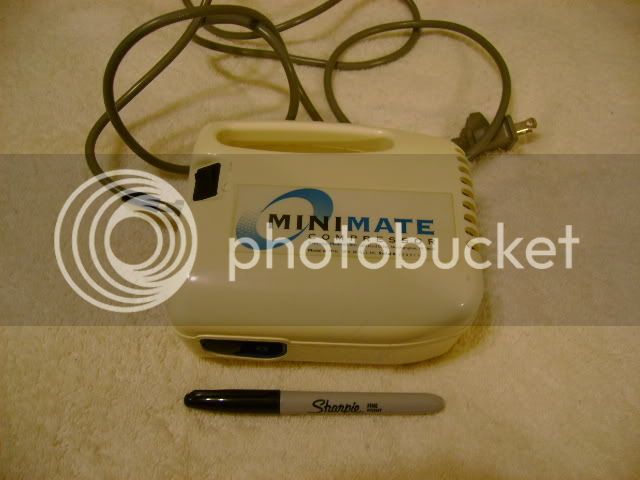
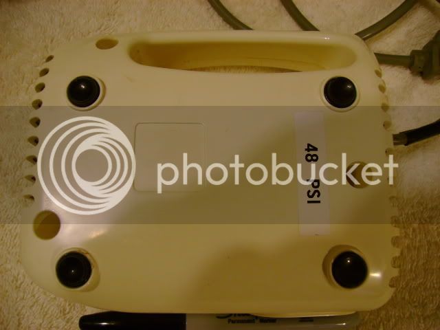
My son used to work for a company that delivered oxygen and other supplies to nursing homes, hospitals, and private homes. One of the items was a "nebulizer". When the customers were done with the unit they were picked up by the company and they disposed of them. Because of state law, they could not use them on another patient.
AirCompresser001.jpg

AirCompresser004.jpg

He cleaned up several of them and gave them to me.
They were set at differant PSI. Some were only a couple PSI and some were quite high. I use one that is set at 48 PSI to run my PM bronze Coke Bottle engine that drive a small machine shop. It is quiet and supplies enough volume to run at high speed.

All the units looked identical. It may be possible that the PSI can be adjusted interally. I never took one apart to find out.

Every large town probably has a similar business and is throwing away these units on a regular basis. Might be worth checking on.
 
The airbrush compressors are very quiet indeed. One can carry on a normal conversation with one running two feet away. Remember, they are intended to be used in a studio environment where excessive noise might be a major detraction.

They're about the size of a toaster and have no accumulator tank. IIUC, they use a diaphragm type pump. And, as I said earlier, they're very affordable.

Even if you eventually buy/make a larger conventional compressor, you may still want to consider the airbrush style. Transporting a large compressor to exhibitions that lack their own air supplies can get tiresome. Also, demoing engines on a coffee table rather than dragging them to the shop now becomes a possibility.

If you intend to build large size engines airbrush compressors may not be up to the job but, for miniature engines, they're really handy.

Resist any suggestion to use PVC for pressurized air. It is not intended for this application and can be very dangerous. If it fails, it can fracture and produce dangerous, possibly lethal, shrapnel.
 
Thanks for the ideas. I wonder if these produce any decent sort of volume and pressure ... doubt it though http://cgi.ebay.co.uk/Rio-Airbrush-Tanning-with-Compressor_W0QQitemZ170273487387QQcmdZViewItemQQptZUK_Health_Tanning_RL?hash=item170273487387&_trksid=p3286.c0.m14&_trkparms=72%3A1298%7C66%3A2%7C65%3A12%7C39%3A1%7C240%3A1318

I remember now, for my last oscillator I tested it with the CO2 bottle from my mig welder, that was OK just to see if it worked but obviously everything gets very cold and it probably wouldn't last very long. Think my bottle has run out now, never actually used it for welding other than practice runs!

Nick
 
I don't think I'd want a rechargeable compressor. Although, the opportunity to make yourself look like a refugee from South Beach while running your engine is enticing, I suppose.

This is the type I was thinking about:

http://www.harborfreight.com/cpi/ctaf/displayitem.taf?Itemnumber=93657

Note that it comes with a built-in pressure gage, regulator and water trap. British weather being what it is, you may find the latter useful.
 

Latest posts

Back
Top