- Joined
- Jan 30, 2011
- Messages
- 365
- Reaction score
- 72
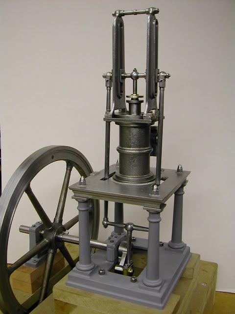
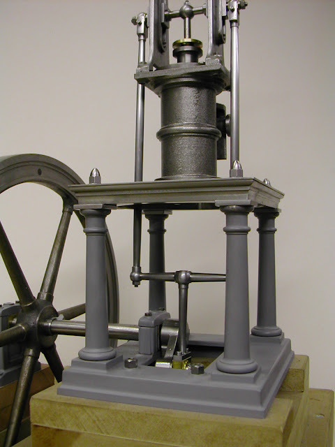
This project, a Waller Table engine from circa 1880, began around 1998 when the original model, designed by Anthony Mount, was published in Engineering in Miniature.
It was decided to make it one third larger which would give a flywheel of 12" diameter and an overall height including plinth of just under 17".
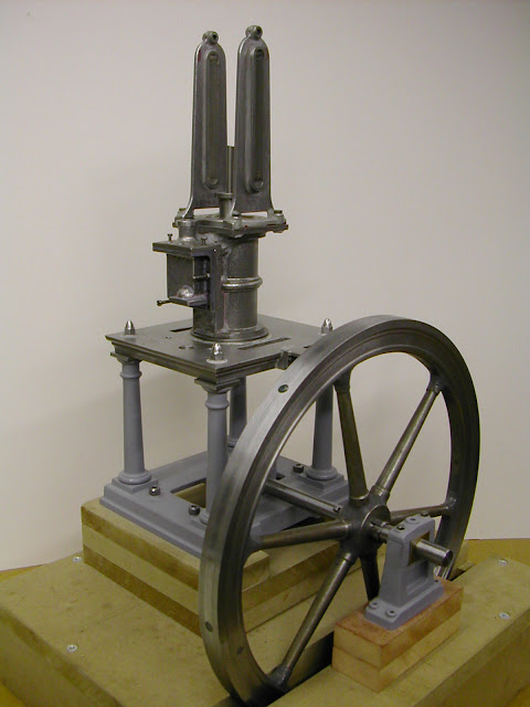
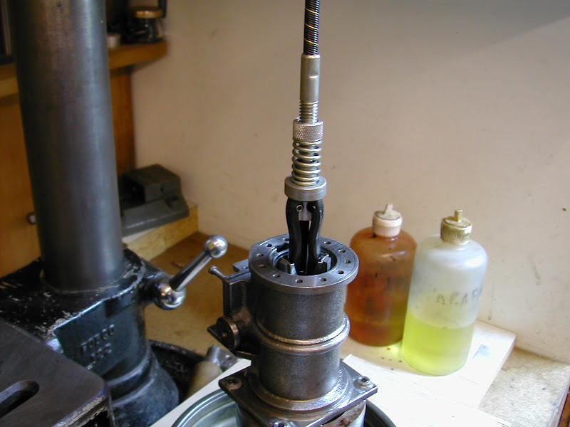
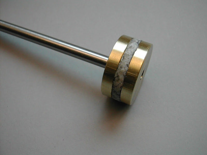
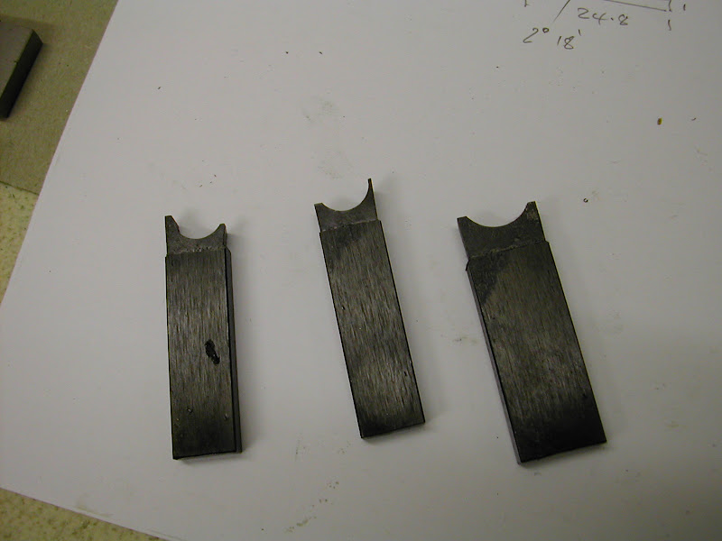
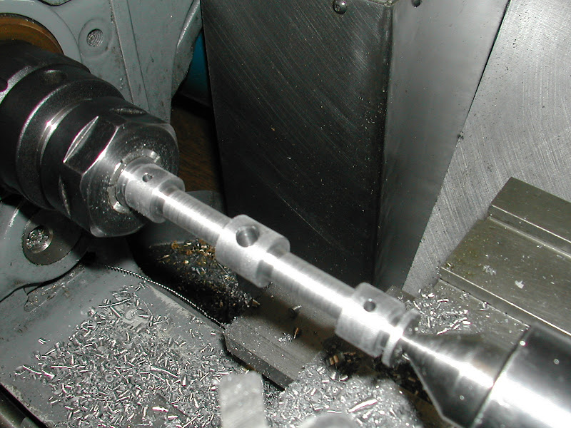
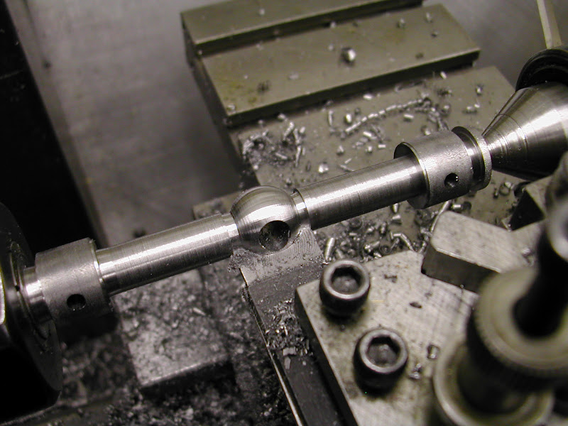
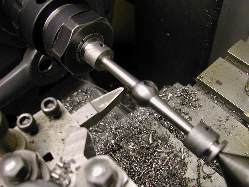
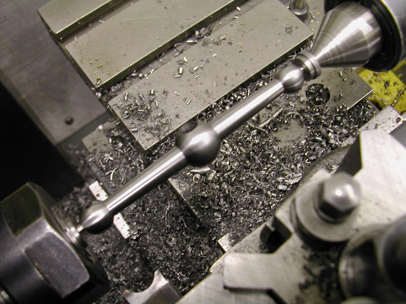
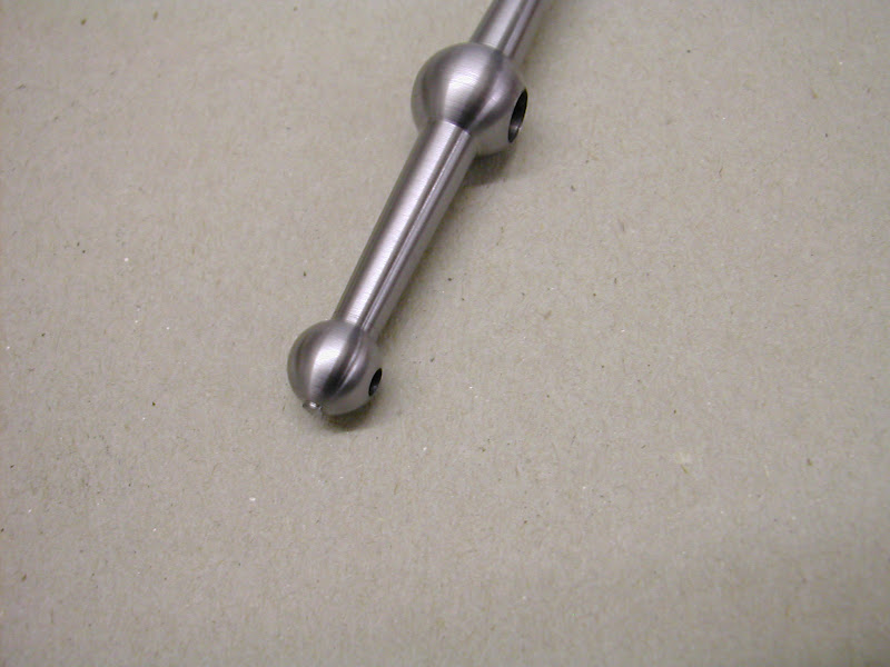
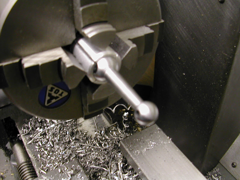
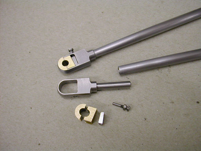
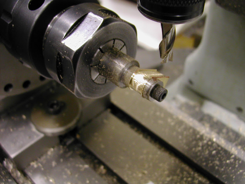
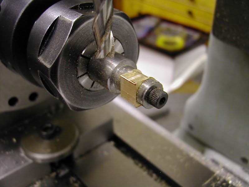
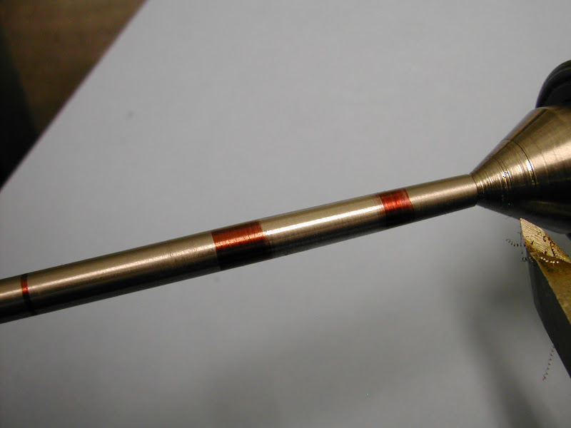
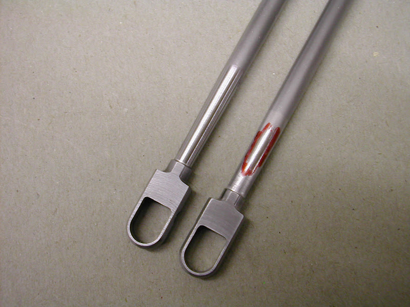
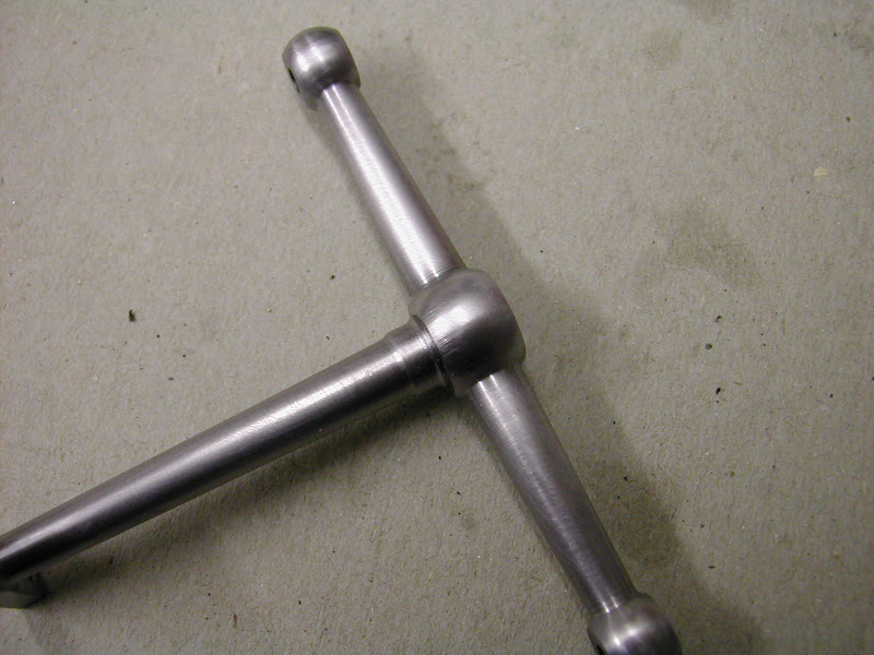
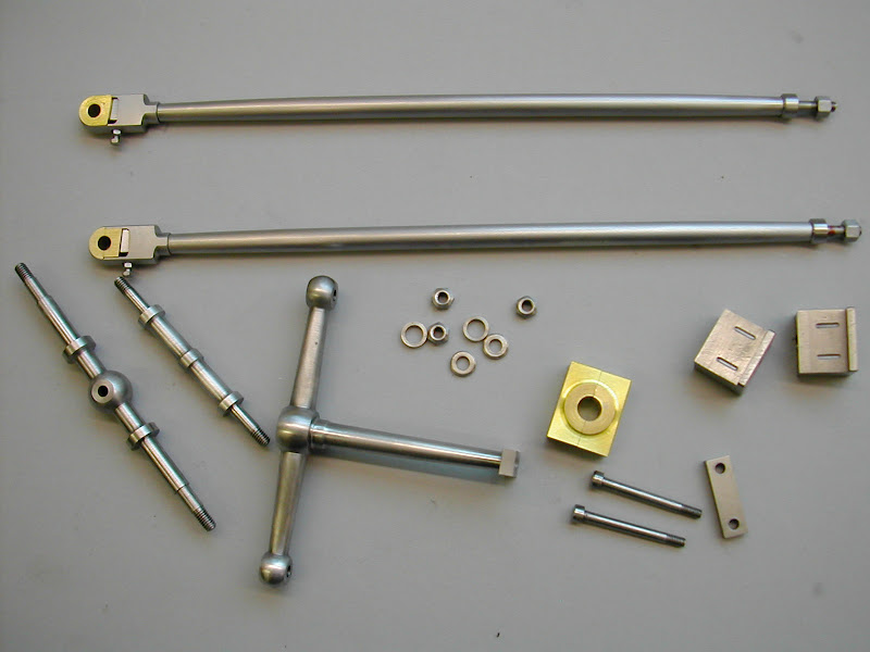
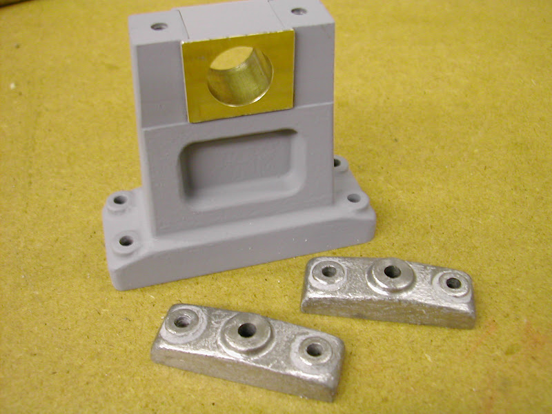
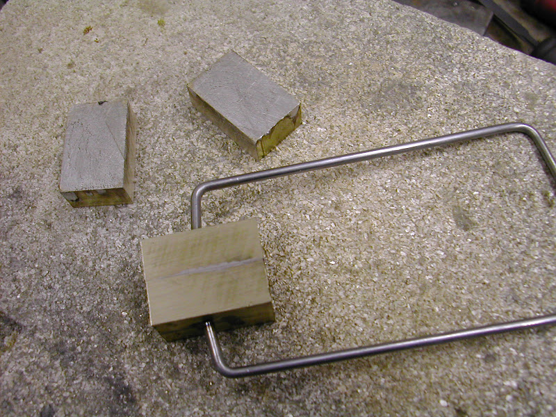
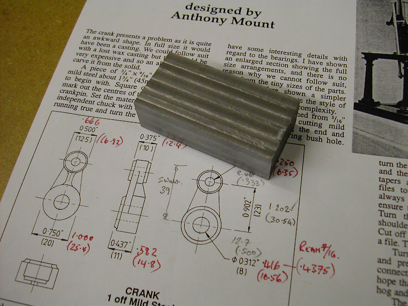
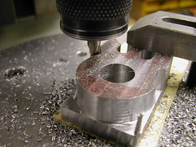
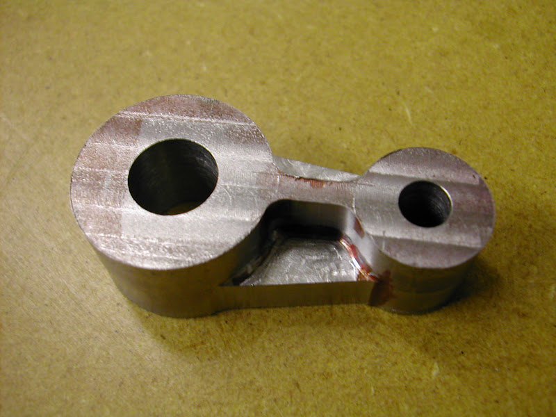
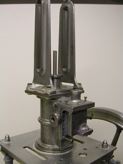
It's all made from spare material - or should that read material going spare - obtained whilst I was still working. Apart from the flywheel, which had the rim milled from a flame cut blank and the spoke holes put in at work all other machining has been done at home. Work has been carried out in fit's and starts over this time - up until a couple of years ago it was just parts languishing in a box but since then it's been erected and slowly worked on at various stages. As such it's very much been an 'infil' project then but hopefully it won't be too long before it's up and running. Currently work is ongoing on the motion gear with the last week seeing some progress on the piston/conrod/big end parts. I don't have too many pics but here are a few that will give some idea of work to date
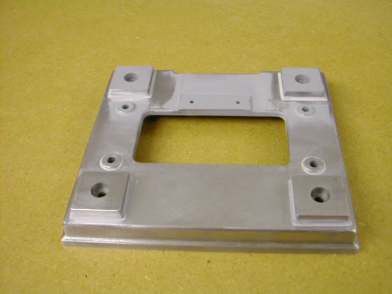
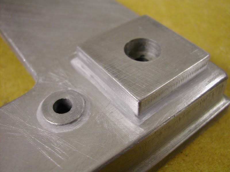
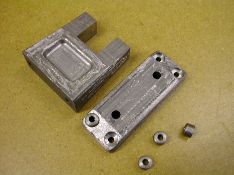
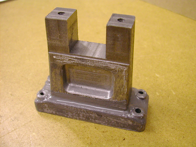
The base and entablature are machined from steel plate. The pads for the columns are separate. Turned from square stock they have spigots that locate holes in the base and are held in place with Loctite then the 'fillets' are applied using JB Weld epoxy steel to give a 'casting' effect. Likewise the hold down bolt pads. All edges are machined/filed at an angle in an attempt to simulate a draft angle.
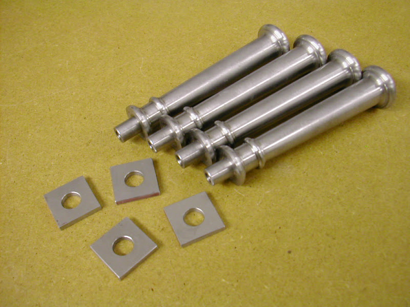
The columns are straightforward turnings all the radii formed with form cutters made from ground flat stock.
The cylinder is a composite one with all parts made from a rather tough cast iron cut from a redundant power press baseplate.
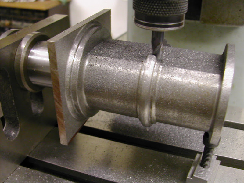
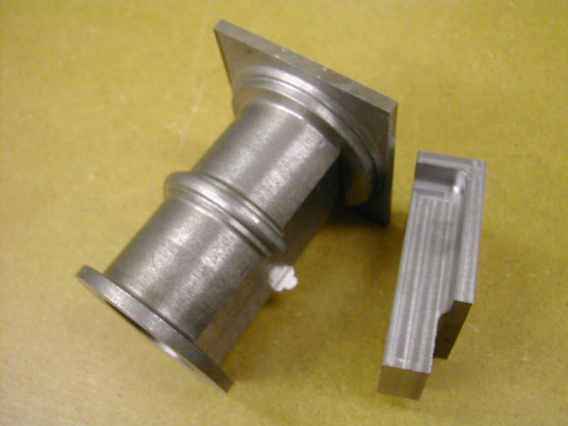
The valve face was fixed to the cylinder using a couple of 8 BA caphead screws and plenty of JB Weld. This stuff has great strength and a high temperature resistance that will easily take dry steam though this engine will probably only ever run on air.
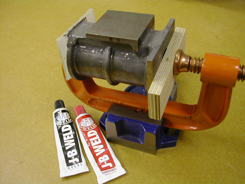
JB is a bit runny and slumps a bit so plenty has to be applied but once cleaned up after twenty four hours curing the effect is reasonable enough
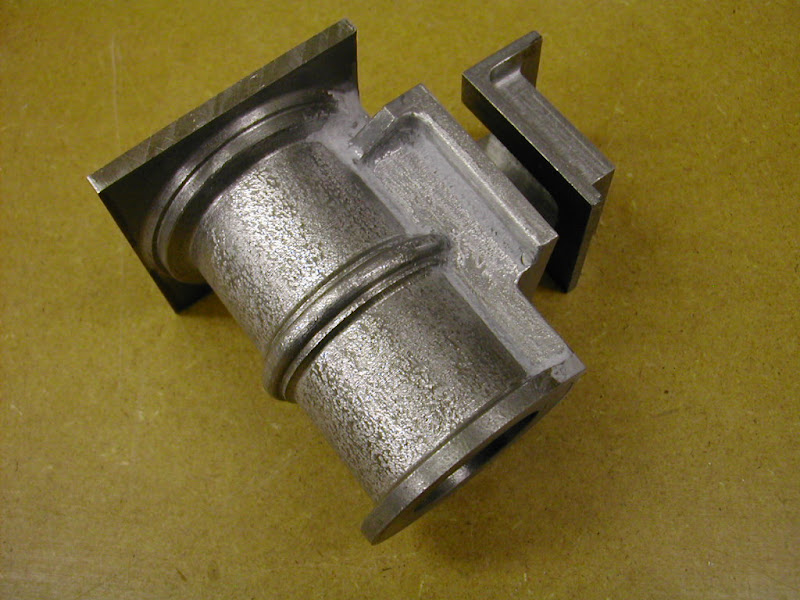
I guess that will give an idea of it's early days - I'll post some more later if you would like and gradually bring it to date.
Hope this is of interest to someone
Regards for now - Ramon
It was decided to make it one third larger which would give a flywheel of 12" diameter and an overall height including plinth of just under 17".

It's all made from spare material - or should that read material going spare

The base and entablature are machined from steel plate. The pads for the columns are separate. Turned from square stock they have spigots that locate holes in the base and are held in place with Loctite then the 'fillets' are applied using JB Weld epoxy steel to give a 'casting' effect. Likewise the hold down bolt pads. All edges are machined/filed at an angle in an attempt to simulate a draft angle.

The columns are straightforward turnings all the radii formed with form cutters made from ground flat stock.

The cylinder is a composite one with all parts made from a rather tough cast iron cut from a redundant power press baseplate.


The valve face was fixed to the cylinder using a couple of 8 BA caphead screws and plenty of JB Weld. This stuff has great strength and a high temperature resistance that will easily take dry steam though this engine will probably only ever run on air.

JB is a bit runny and slumps a bit so plenty has to be applied but once cleaned up after twenty four hours curing the effect is reasonable enough

I guess that will give an idea of it's early days - I'll post some more later if you would like and gradually bring it to date.
Hope this is of interest to someone
Regards for now - Ramon




![DreamPlan Home Design and Landscaping Software Free for Windows [PC Download]](https://m.media-amazon.com/images/I/51kvZH2dVLL._SL500_.jpg)


