It didn't take long for reality to set in before I put aside my plans to build a 5" gauge loco in favour of something more suited to my limited equipment and even more limited experience.
A rummage through the storeroom-cum-garage-cum-workshop soon unearthed a box containing two sets of rusty castings; one set each for a Stuart 10V & 10H that I had been given a few years back. Heading over to the lathe I whiled away a pleasant few hours experimenting with holding the castings in the lathe chuck or on the milling table in various configurations, but I just couldn't work up the courage to actually attack those expensive and now hard to obtain castings with a cutting tool. So the castings were once again packed away and a decision was made to attempt a relatively simple engine that I could possibly complete successfully which could also be constructed from easily replaceable stock material. A perusal of the web turned up a wealth of possibilities of which I eventually decided on a little oscillating engine - Elmer's #25.
My "workshop" consists of: a workbench in the corner of the garage, a Unimat PC Basic lathe/mill, and the miscellaneous hand tools, measuring instruments and other odds and ends that I have managed to accumulate over the years.
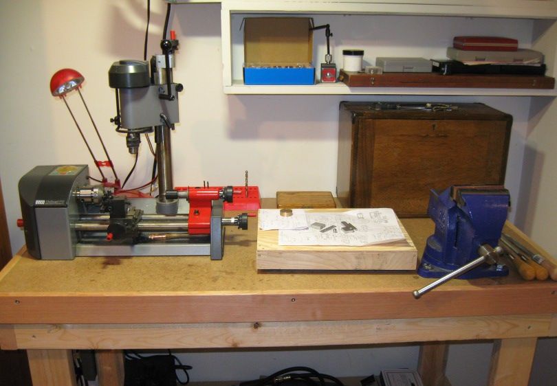
The wooden rectangle in the middle of the bench on which can be seen the embryonic bits of my budding engine, is a cover for a 9 x12" granite surface plate. There is nothing too remarkable about the cover other than the brass screws I first tried assembling it with. These were bought at one of the big-box DIY stores, no country of origin on the label, just marked imported, three guesses as to where they were made?
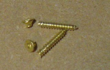
And that was after I had pre-drilled the holes in the soft wood used for the sides!
-------------------
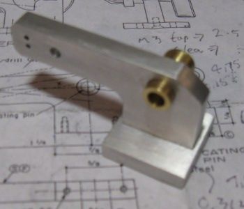
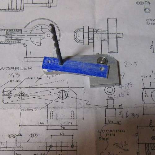
Actual engine construction started with a piece of 1/4" thick aluminium that was soon destined to become both the frame and the base. I initially planned on using the mill to machine the frame to shape, but never having used a mill before I instead opted for a hacksaw and some files. On the whole I am happy with how it turned out, but the inner curved corner does have a slight kink where it joins the straight.
The frame was then followed by the rectangular base. This time I threw caution to the wind, mounted the milling vice on the mill table and milled it to size ... eventually ... on the third try. What was not immediately apparent to this novice, is that when the table is traversed, that unless both vice and table are scrupulously aligned to the lathe axis, nothing comes out parallel.
Next puzzle to solve was how to align the frame and base for drilling the fixing holes. After marking out and drilling the two holes in the base to tapping size, I eventually hit on clamping the frame to the base, aligning it correctly, turning over and then clamping the clamp in the drilling vice.
For some reason figuring this out (and I am sure there is probably a better way), something that is probably trivially simple to an experienced machinist, gave me an enormous amount of satisfaction.
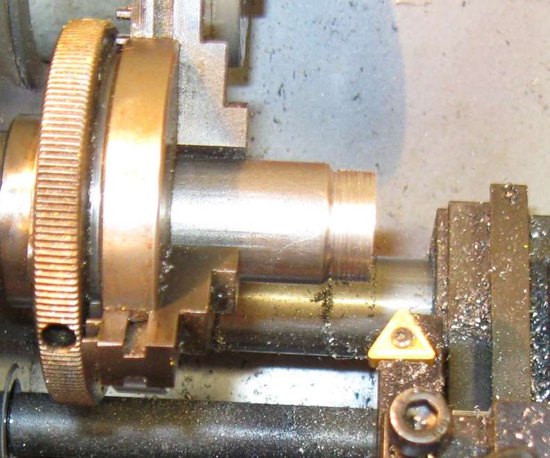
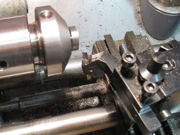
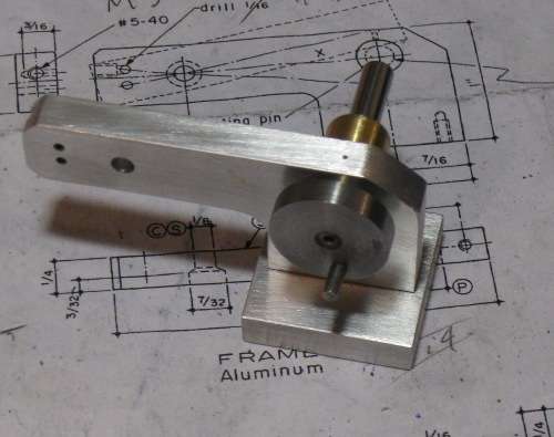
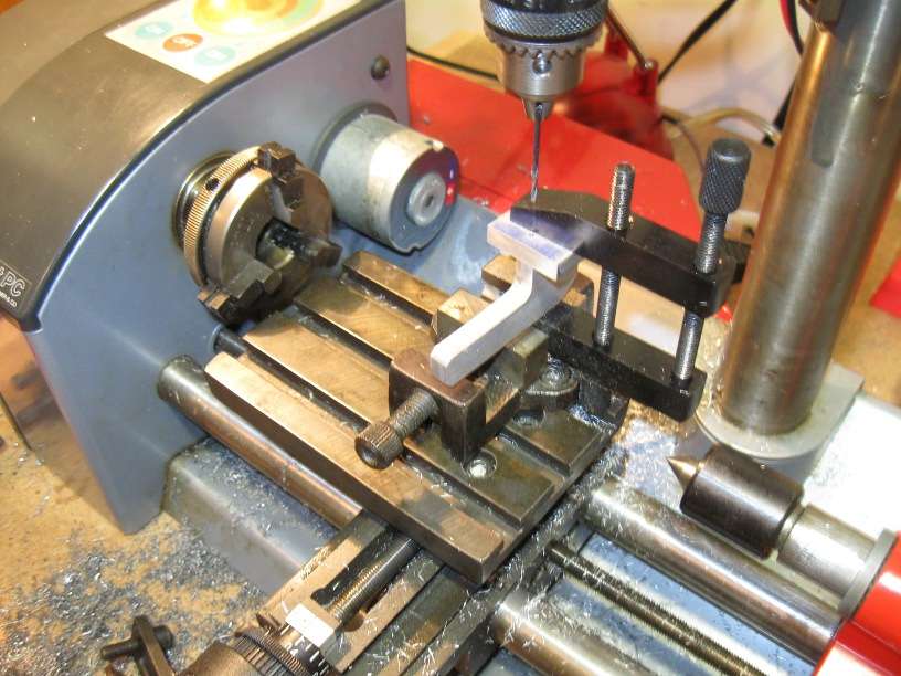
After drilling the crankshaft bearing and pivot pin holes in the frame, the port drilling jig was made up out of a strip of steel with three carefully placed holes. The next item, was my first real turning job - the 'locating pin'. This is used in combination with the port drilling jig to place the port holes in the frame as can be seen from the next picture.
Prior to this I had only really experimented with the lathe i.e reducing scraps of metal to swarf. Now I was faced with turning something a close fit. On my first attempt I completely overshot the mark, but my second attempt was much more successful. This probably had something to do with the realisation that those markings on the hand-wheels are actually useful and accurate!
That's it for today, so far it has been fun") But what came as the biggest surprise to me is just how little time is spent actually machining in comparison to marking out and setting up.
But what came as the biggest surprise to me is just how little time is spent actually machining in comparison to marking out and setting up.
The other thing that surprised me is just how much arithmetic is involved in machining a part to size. The plans are in fractions of an inch, the digital vernier in decimals both inch and metric (which also makes it a handy tool for converting between the two) and the lathe dials are metric. I don't want to get into a metric versus imperial debate, but as someone who is comfortable with both systems, I found metric with its consistent use of decimals so much simpler to use as a beginner when compared to the dual format fractions/decimals used with inches.
Clive
A rummage through the storeroom-cum-garage-cum-workshop soon unearthed a box containing two sets of rusty castings; one set each for a Stuart 10V & 10H that I had been given a few years back. Heading over to the lathe I whiled away a pleasant few hours experimenting with holding the castings in the lathe chuck or on the milling table in various configurations, but I just couldn't work up the courage to actually attack those expensive and now hard to obtain castings with a cutting tool. So the castings were once again packed away and a decision was made to attempt a relatively simple engine that I could possibly complete successfully which could also be constructed from easily replaceable stock material. A perusal of the web turned up a wealth of possibilities of which I eventually decided on a little oscillating engine - Elmer's #25.
My "workshop" consists of: a workbench in the corner of the garage, a Unimat PC Basic lathe/mill, and the miscellaneous hand tools, measuring instruments and other odds and ends that I have managed to accumulate over the years.
The wooden rectangle in the middle of the bench on which can be seen the embryonic bits of my budding engine, is a cover for a 9 x12" granite surface plate. There is nothing too remarkable about the cover other than the brass screws I first tried assembling it with. These were bought at one of the big-box DIY stores, no country of origin on the label, just marked imported, three guesses as to where they were made?
And that was after I had pre-drilled the holes in the soft wood used for the sides!
-------------------
Actual engine construction started with a piece of 1/4" thick aluminium that was soon destined to become both the frame and the base. I initially planned on using the mill to machine the frame to shape, but never having used a mill before I instead opted for a hacksaw and some files. On the whole I am happy with how it turned out, but the inner curved corner does have a slight kink where it joins the straight.
The frame was then followed by the rectangular base. This time I threw caution to the wind, mounted the milling vice on the mill table and milled it to size ... eventually ... on the third try. What was not immediately apparent to this novice, is that when the table is traversed, that unless both vice and table are scrupulously aligned to the lathe axis, nothing comes out parallel.
Next puzzle to solve was how to align the frame and base for drilling the fixing holes. After marking out and drilling the two holes in the base to tapping size, I eventually hit on clamping the frame to the base, aligning it correctly, turning over and then clamping the clamp in the drilling vice.
For some reason figuring this out (and I am sure there is probably a better way), something that is probably trivially simple to an experienced machinist, gave me an enormous amount of satisfaction.
After drilling the crankshaft bearing and pivot pin holes in the frame, the port drilling jig was made up out of a strip of steel with three carefully placed holes. The next item, was my first real turning job - the 'locating pin'. This is used in combination with the port drilling jig to place the port holes in the frame as can be seen from the next picture.
Prior to this I had only really experimented with the lathe i.e reducing scraps of metal to swarf. Now I was faced with turning something a close fit. On my first attempt I completely overshot the mark, but my second attempt was much more successful. This probably had something to do with the realisation that those markings on the hand-wheels are actually useful and accurate!
That's it for today, so far it has been fun
But what came as the biggest surprise to me is just how little time is spent actually machining in comparison to marking out and setting up.The other thing that surprised me is just how much arithmetic is involved in machining a part to size. The plans are in fractions of an inch, the digital vernier in decimals both inch and metric (which also makes it a handy tool for converting between the two) and the lathe dials are metric. I don't want to get into a metric versus imperial debate, but as someone who is comfortable with both systems, I found metric with its consistent use of decimals so much simpler to use as a beginner when compared to the dual format fractions/decimals used with inches.
Clive


![DreamPlan Home Design and Landscaping Software Free for Windows [PC Download]](https://m.media-amazon.com/images/I/51kvZH2dVLL._SL500_.jpg)