A raw beginner attempts an Elmer's 25

Home Model Engine Machinist Forum

Help Support Home Model Engine Machinist Forum:

This site may earn a commission from merchant affiliate links, including eBay, Amazon, and others.
You could even scribe a thin separation line and simulate a head that was bolted on with micro hardware. H 00-90 hex head or nut should be about .078 across the flats, so 6 of those on the end could look pretty cool. You would want an .035-in drill bit to tap the holes and a .052 for a close fit clearance. Personally I would go with the larger bit and a drop of CA on a toothpick to secure them. No need to be breaking micro taps.

www.scalehardware.com is one source for real and simulated nuts and bolts in micro sizes and Google turns up a bunch of others.

Thayer
 
The little nuts and bolts are a nice idea, but I need to ease up on the creativity, that was what got me into trouble in the first place :)

... so taking the more conservative approach, I opted for fitting a ring around the end of the cylinder.
But after rummaging through the meagre contents of my scrap box and not finding any suitable material, it dawned on me that all that is required is a small filler piece wide enough to cover the port holes in the frame when the cylinder is rotated to top and bottom dead centre.

I hacked off a little chunk of brass from the remaining piece of bar that had been used for the cylinder and then filed a little half round indentation until it was a close-ish fit to the end of the cylinder.
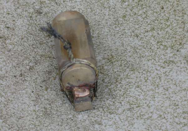
I thoroughly cleaned both the cylinder and filler piece with alcohol before carefully applying flux to both parts with a tooth pick. Not too sure of how to hold the structure together for soldering my eyes fell on some stranded picture hanging wire which was easily hand twisted to hold the parts together. Three tiny pieces of silver solder were placed at the joints, the propane torch lit, and the cylinder gently heated. Nothing happened. Being over cautious and never having used silver solder before, I had the torch turned down far too low. I slowly turned it up and then in an instant the solder liquefied and as if by magic was sucked into the joints.
Here it is cooling down, the rough looking projection at the back is the filler piece that started out far too thick:

cylindersalvagesolder.png


I was a bit disappointed when it cooled down, I hadn't expected it turn out quite so messy, but nothing ventured, nothing gained, so I dropped it into some citric acid solution and left if for a few hours. After which, other than being a little duller, it looked as good as new again :)

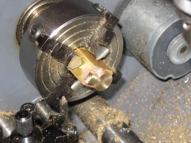
I then skimmed the back of the cylinder in the four jaw chuck to level the filler piece flush with the back:

cylindersalvageskimming.png


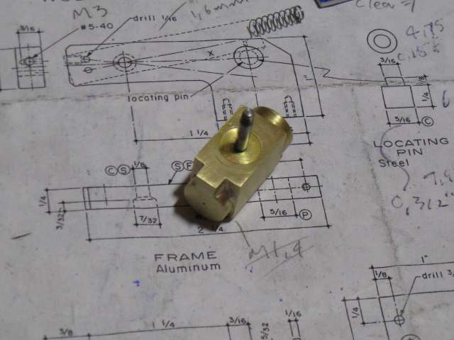
Followed up by skimming the bearing face, and then fitted the pivot pin:

cylindersalvagefinished.png


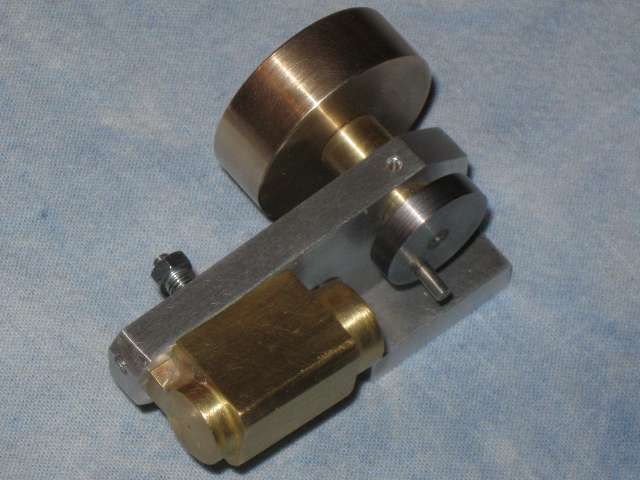
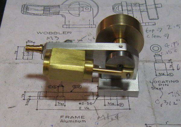
Current state of play - waiting for piston, connecting rod and airline barb:

pistonnext.png


Well done with the repair, it looks good and you have a unique cylinder ;)
 
Nicely done. If you ask me, it looks like it was supposed to be that way. Thm:
 
Nice save Clive...as already noted...look like it's supposed to be that way. The project is coming along quite well and I am still following along with interest!!

Bill
 
Clive, that really looks the part and quite honestly, it is rather more elegant than the solutions I was envisioning as well!

Thayer
 
The lovely spring weather of the past few days had one unfortunate side effect. By managerial decree I was presented with a box of seedlings and banished to the wide outdoors for a spot of gardening. But in the end, with fresh mud still under my finger nails I managed to grab a few hours to myself which I spent in the workshop.

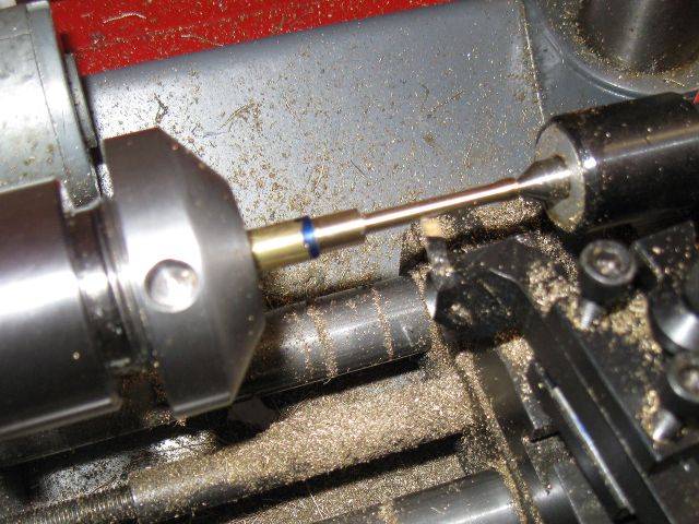
First task was the piston rod seen being turned here. I left it long enough for the little bulge closest to the centre to be removed prior to threading 3mm. The thicker part closest to the chuck was destined to be cross drilled for the crank pin.

pistonroda.png


To say that the cross drilling was not too successful is an understatement. I aligned a far too large V-block under the drill. The little piston rod was dwarfed by the stirrup clamp and the only way I could get it fixed in place was by interposing a piece of scrap between the clamp and the rod in Heath Robinson fashion. Needless to say something slipped once drilling started and the drill entered off centre. When it grabbed on exiting the piston rod freed itself from the clamp. Attaching itself to the drill bit it did a remarkable impression of a Sikorsky chopper. It seemed about to take off by the time I managed to hit the power switch. Fortunately no injuries and no damage, not even to the bit.
There is definitely something to be said for beginners starting with low powered machinery :hDe:

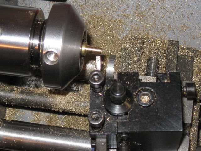
Next I decided to make an airline barb. After looking at pictures I was somewhat puzzled as how to turn the taper on each segment when it dawned on me that a tool of the correct width rotated to the desired angle could be plunged straight in which is what I did with a parting tool:

hosenipple.png


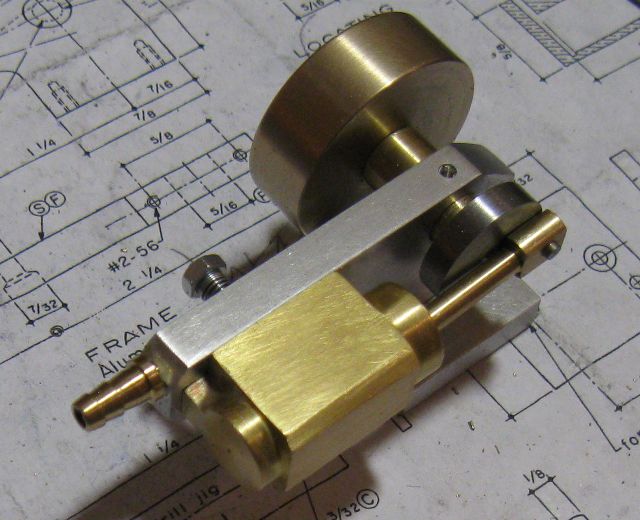
Buoyed by my success with the barb, I milled the sides of the piston rod flat and assembled the engine which can be seen here, now almost complete except for one last item, the piston.

pistonnextb.png


Not obvious from the photo is just how off centre the crank pin hole in the piston rod is. It is definitely going to have to be remade, but as I am keen to see the engine (hopefully) working, I think I will do the piston first and replace the rod after that.


Clive

Slowly but surely you are getting there. Keep it up.

Vince
 

Last night I made the piston.

Turning it down to size was a fairly protracted experience because somehow I just can't seem to get consistent readings with the digital calliper when measuring a diameter - no two readings are the same. It is not the calliper it is me :(
So to ensure that I didn't make the piston too small, once it was close-ish to size I progressively reduced it by taking cuts of half a division - 0.025mm checking against the cylinder between each cut. When it was only just too large to go into the cylinder I switched to a parting tool for the oil grooves. After which I slowly reduced the piston diameter by wrapping a loop of emery cloth around it while rotating the lathe at high speed until the piston slid smoothly into the cylinder.
As a result the piston now appears to be a nice close fit, dropping it vertically into the cylinder while covering the inlet/exhaust hole causes it to descend very slowly, unblocking the hole causes it to drop rapidly.

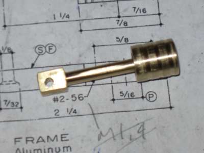
Here the piston has been drilled threaded and attached to the piston rod:
pistonandrod.png


Clearly visible in the photo is the badly offset crank pin hole.
Undeterred by this "cosmetic" blemish I assembled the engine all ready for its first test run. But I was disappointed to find that the engine binds at one spot when rotated. After checking the crank pin and crankshaft for squareness, I guess the off centre hole is the most likely culprit. So the engines maiden voyage will have to be postponed until after I make a new piston rod, hopefully this weekend.

 
Calipers are the wrong tool for measuring diameters on the lathe. Get a micrometer and you'll get more accurate and more repeatable measurements.

Not to be a nanny but since you're a self-admitted novice...

Be very, very careful when using emery strips on the lathe. Wrapping them completely around the work can easily trap a finger and do you great damage. Never wrap a loose end around any part of your anatomy.

Far better is to wrap the emery strip over a stick or a file and use that as a very fine file on the work. One simple and cheap method is to use a piece of yardstick or a wooden paint stirrer and two binder clips.
 
mklotz said:
Not to be a nanny but since you're a self-admitted novice...

That isn't being a nanny, it is excellent, and most welcome advice, thank you :)

and thanks for the tip on the micrometer, I hadn't really considered one as I had naively assumed that the modern digital calliper was a catch all replacement for most measuring instruments.

 
Calipers need technique to get accurate measurements. Practice with a micrometer standard or a gage block/pin - something with a precisely known size. The jaws must sit flat on the work and pressure is applied directly to the jaws using two fingers - not the little roller thing for moving the movable jaw quickly.

Naturally, the jaws must be scrupulously clean. Even with all these dicta observed and assuming high quality calipers like Mitutoyo, you'll be hard pressed to measure more accurately than a thousandth.
 
Nice recovery on the cylinder Clive. Whilst the recovery advice given was excellent it’s always nice to be able to come up with your own solution to the problem and it looks as it was meant to be like that. Good one.

Cheers Les
 
Well I hadn't quite abandoned my build :)
More like a broken lathe drive belt had put my machinist ambitions on hold for a few weeks.
The lathe uses off the shelf timing belts but the particular sizes and pitch can't be too popular as I had a really hard time getting hold of these. After I eventually found a US company willing to actually mail a few of these tiny belts to Canada in a padded envelope, I then gained first hand experience at just how inefficient the US postal service is. It took nearly three weeks for the envelope to arrive. In contrast tools and other items ordered from the UK with comparable shipping costs typically arrive in four to five days.

Once the lathe was up and running, the first thing I did was to remake the piston rod. This time taking a considerable amount of care to ensure that the crank pin hole was centralised. Once the new rod was fitted, I was pleased to find that any hint of binding had disappeared and the engine now turned over smoothly.
Not having a source of compressed air, I had to wait until last night when I visited a friend with a compressor to try it out and was stunned to find that it WORKS !!! :big: :big:

Here the completed engine:
finishedelmers25.png

Although my engine is far from perfect, and I made a number of mistakes along the way, I think this only added to what was an incredibly valuable learning experience.

What's next ?
Having followed so many of the excellent builds on this site, paying particularly note to the set-ups and procedures used by others, I have it in mind to try and improve the workshop facilities by making a few tools.
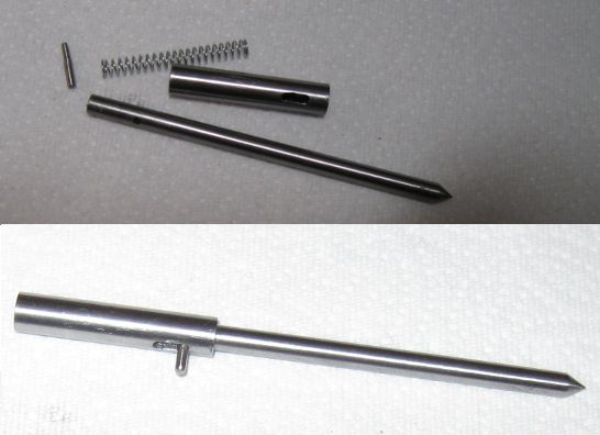
To start out, I spent the last two evenings making a centre finder to a design published in "Model Engineer" a few years back. Here it is, the individual pieces, and then assembled:
centrefinder.png


Clivel-

Congrats on your first runner. Well done.

-Bob
 
Thm: Well done Clive ;D

Your engine looks just dandy, and you handled the little set-backs along the way really well :)
It's the learning experience and fun along the way that really counts - as I'm sure you found out ;)

I'm raising a glass to you right now; Bottoms Up *beer*

Kind regards, Arnold
 
Good job getting your engine going Clive, watching an engine run is the best encouragement. The centre finder is a tool I can't do without and the first one I made. Will be interested to see what engine you chose next.

Jan
 

Latest posts

Back
Top