A new attempt at making piston rings

Home Model Engine Machinist Forum

Help Support Home Model Engine Machinist Forum:

This site may earn a commission from merchant affiliate links, including eBay, Amazon, and others.
Cover piston and ring with #30 motor oil. Lay ring on top of piston and spread ring as far apart as you think you can without breaking it with your thumbs and start one side of ring (right at the gap) down over the side of the piston. Work your way around until the ring is spread out enough to set down over the top of the piston. Then tease it down incrementally until it goes into the ring groove and relaxes. Damn, it's harder to explain it than it is to do it.
My dad taught me to install rings when I started working for him in the family auto shop as a kid. It cost him a few broken rings to let me learn, but once you've learned it you don't even think about it. I start the ring over the piston opposite the gap, keep some pressure inward on each side about 120 degrees from the gap while I gently urge the gap ends over the edge of the piston. To slide the ring over the piston and the intermediate ring grooves, its basically the same thing: keep some inward pressure on the rings at 120 degrees from the gap while opening the ring at the gap. What you are really trying to do is spread the bending force around the ring rather than just opposite the gap.

Like you said, the explanation is much harder than actually doing it.

Don
 
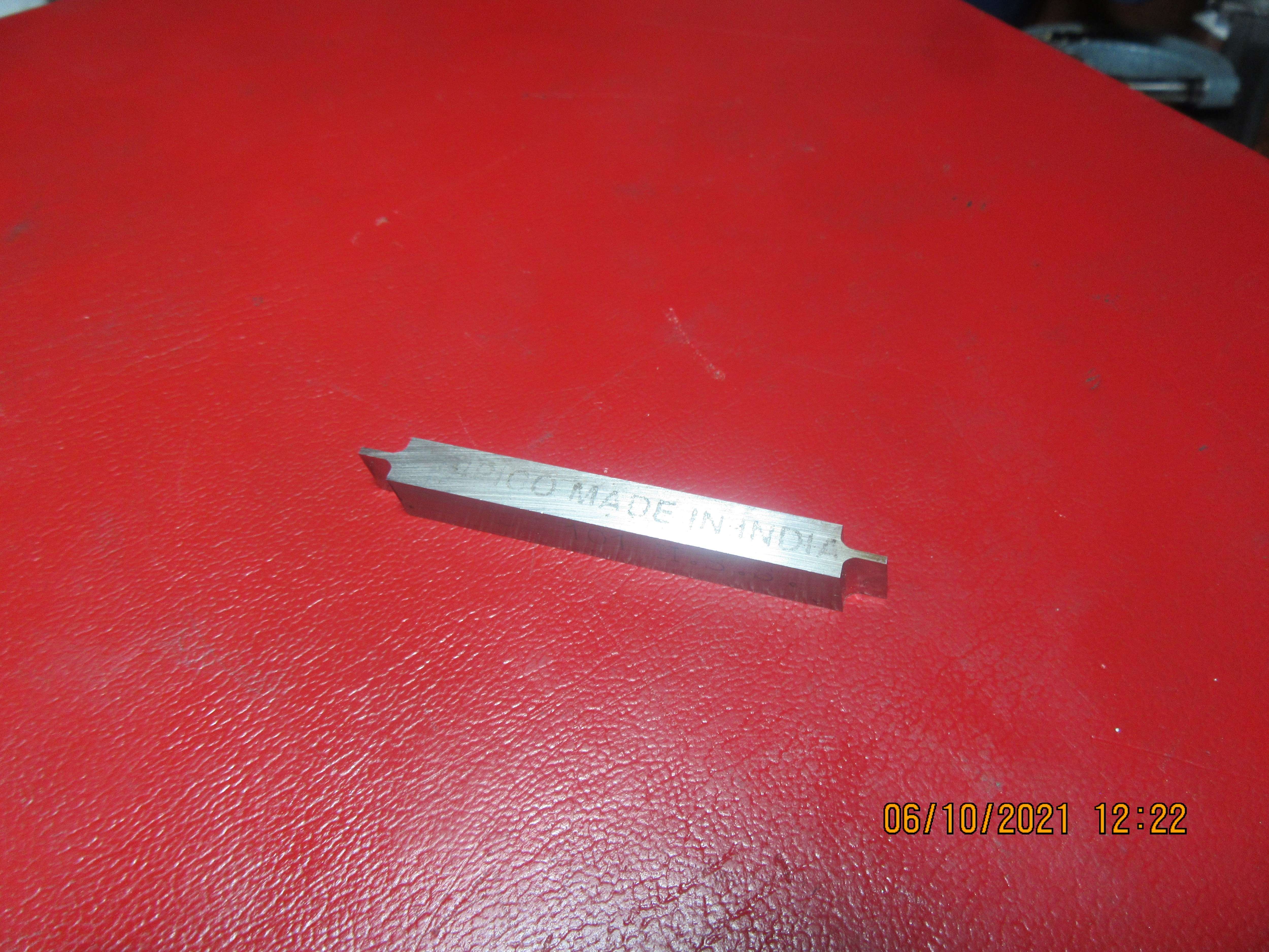
Today I picked up my 1 mm (0.039"0 lathe tool from Can-cut, a local sharpening service. Yes, it does have a bit of side relief on it. He made it using a surface grinder. ---Yes, I paid $75 for it, but this is still only about 1/2 of what I would pay for a carbide and toolholder out of USA. Next step will be to machine a holder for this tool and see exactly what width of cut it actually makes in a 1" diameter piece of aluminum round stock.----And yes, I agree with the sentiment "More money than brains".
efm0SQ.jpg
 
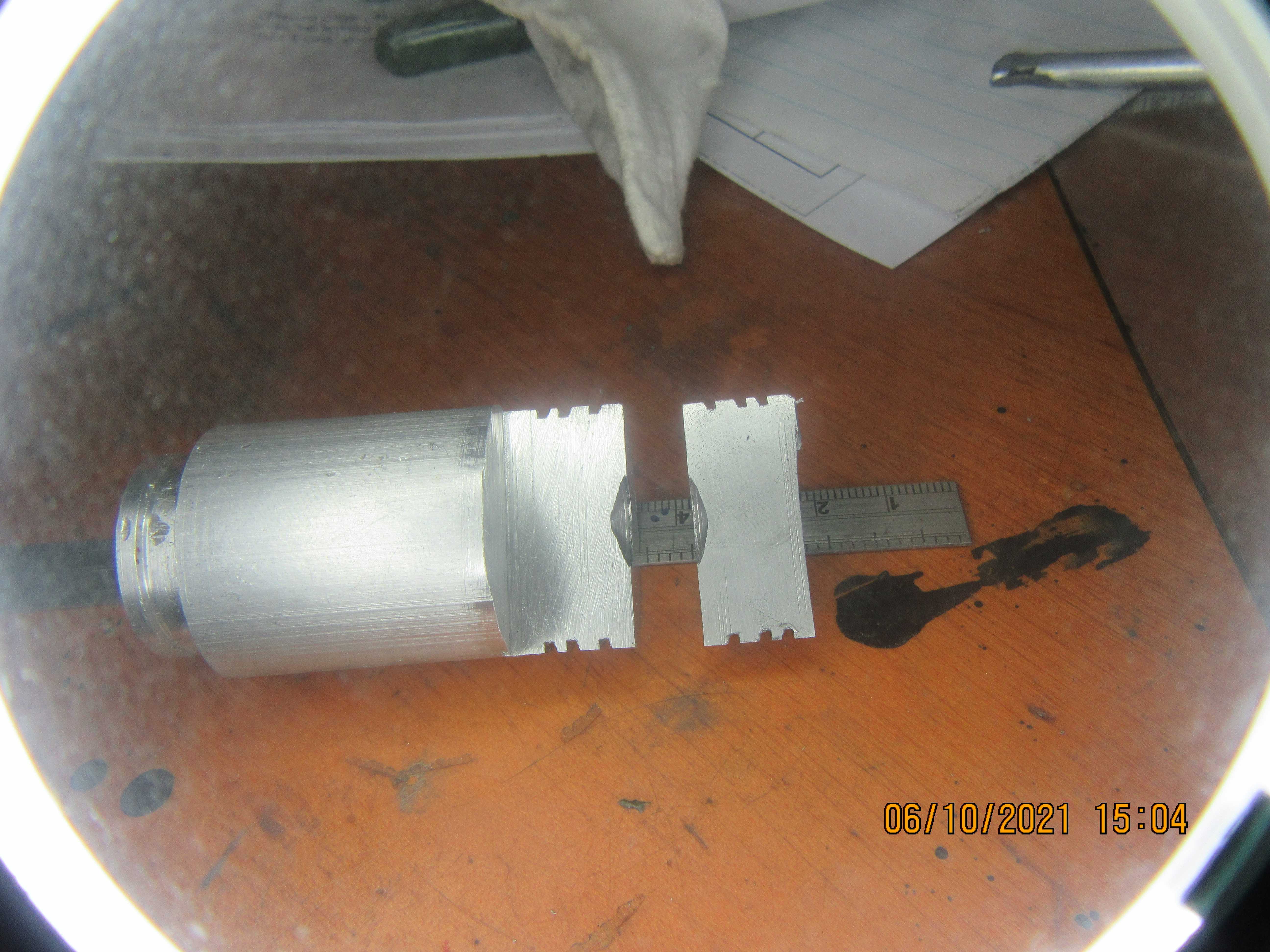
Something very fishy is going on, and I don't know what. My new tool is setting at exactly the correct height (centerline of spindle), perfectly square to the long axis of the lathe, and the tool is ground perfectly square across the end. I made three plunge cuts, using the cross slide to advance the tool into the cut, with lots of wd40 as lubricant. My new tool is set up with very little unsupported "stick out". Then I cut the aluminum round blank on my bandsaw to expose a cross-section of the cut. All of these cuts look crooked to me. I don't think there is any way that a ring can seal against either side of the plunge cut. My cross slide is set at 90 degrees to the long axis of the lathe. Does anyone have an explanation of what may be going on here?
zXNF93.jpg
 
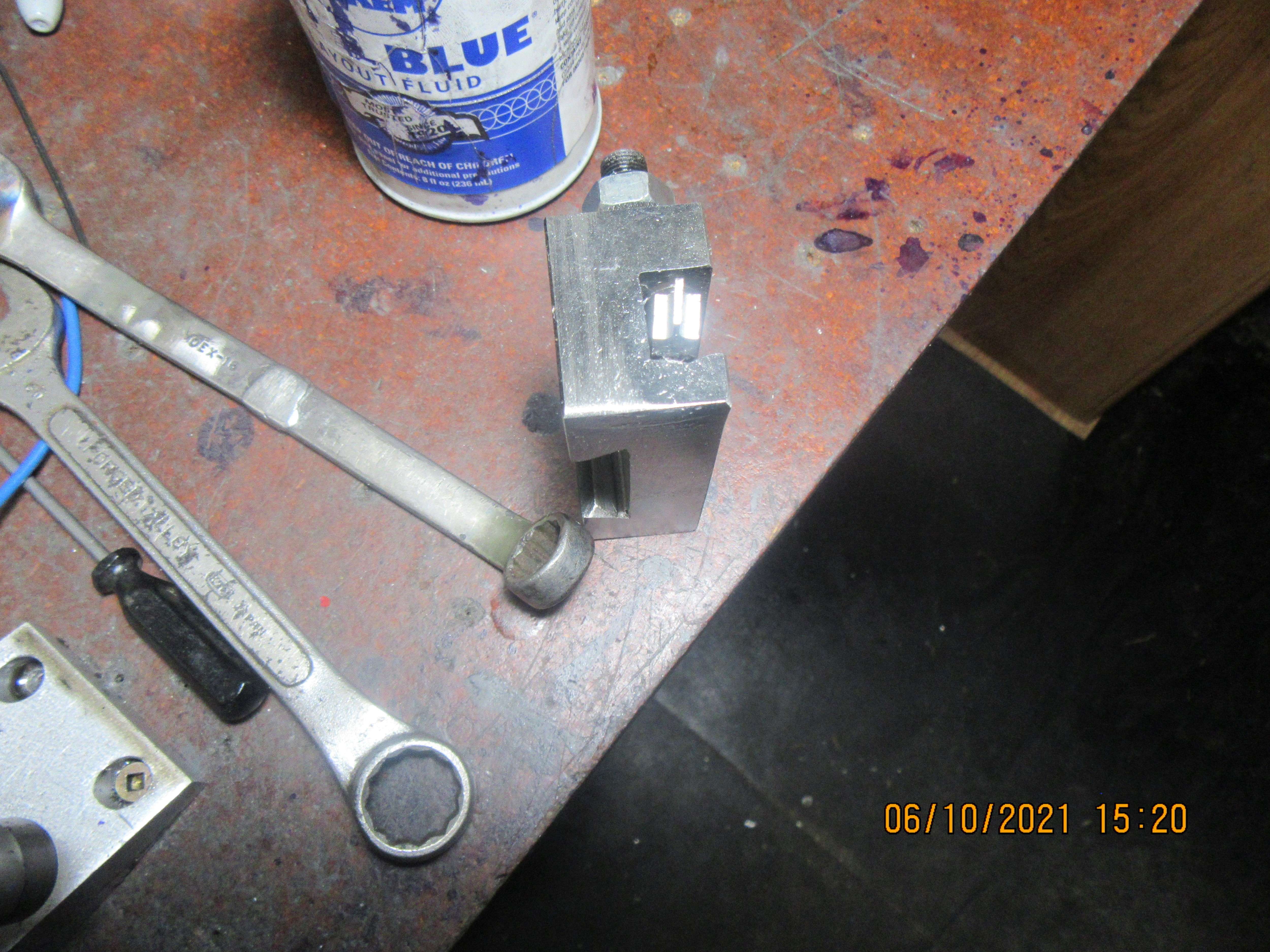
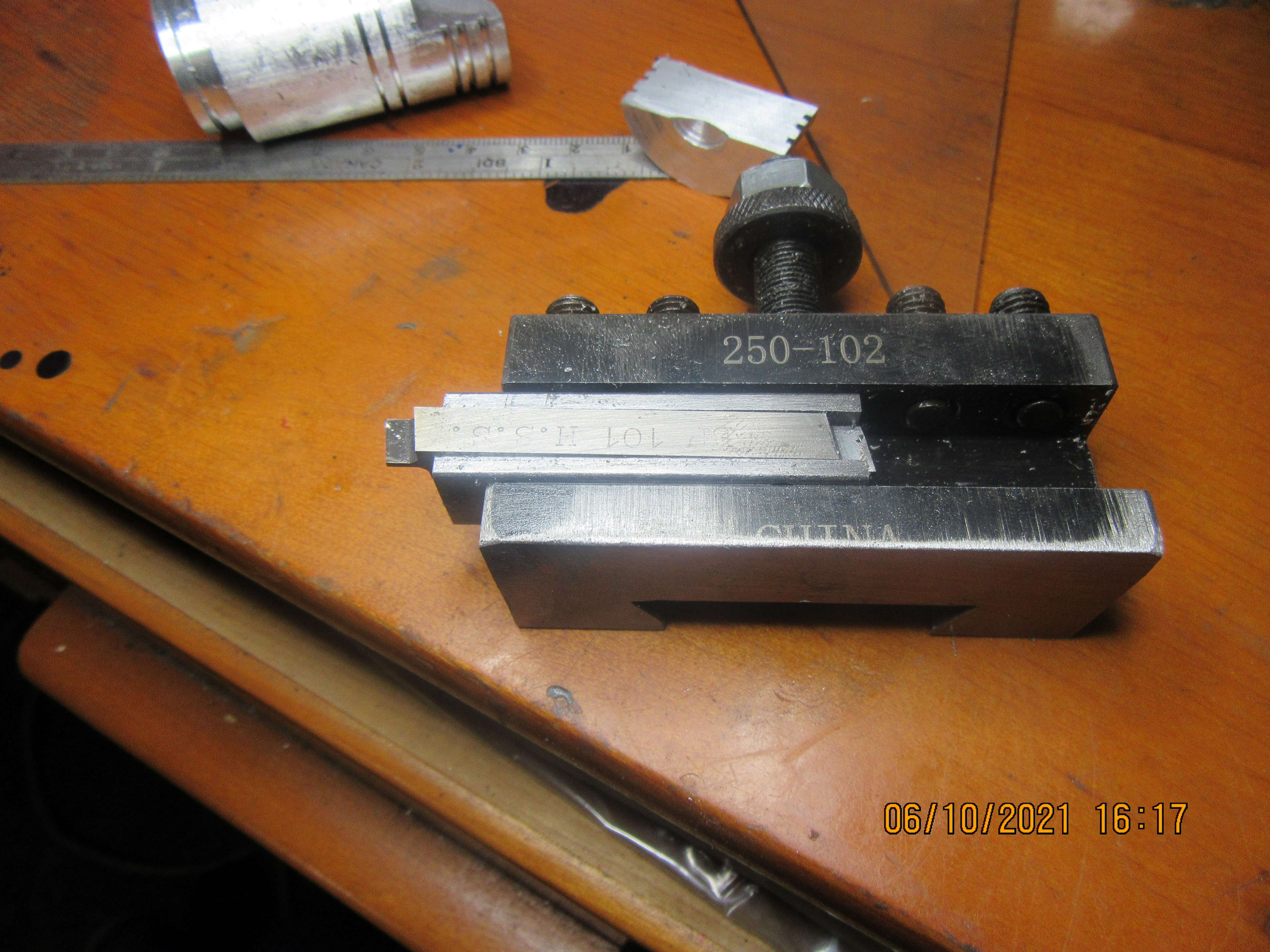
Cancel that last question.--Investigation shows that tool was setting crooked in holder. I will make a better tool holder and try this again.
9uEXTE.jpg
 
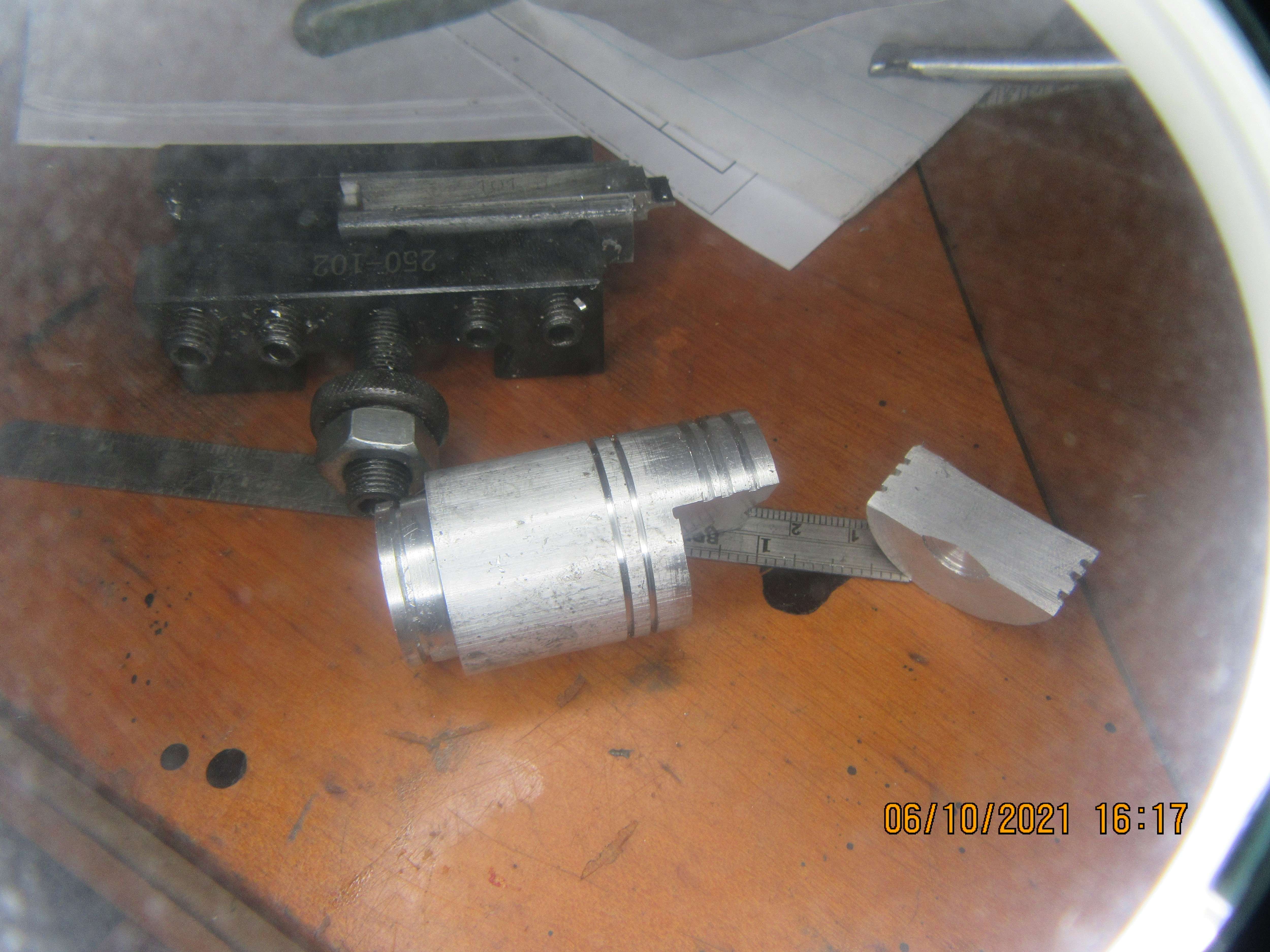
Okay---Proper tool holder gives perfect grooves. The grooves measure 0.040" wide with my Vernier caliper, so I'd say it's good. The grooves appear at a proper 90 degrees to long axis of part. I'm happy with the new tool.
SbmQIK.jpg

J3xA9U.jpg
 
Well done Brian! - So good when someone actually makes a mistake, then works out the solution and gives the whole unadulterated story. Teaches us more than just machine work. Makes me look harder at what I am doing to try and improve myself.
Someone clever once told me "Don't be proud of making mistakes, be proud of the performance of how you found the mistake and recovered from it, learned lessons and taught others, so they don't make the same mistakes.
Now you (I.E. "someone clever") have done just that and set an example for those that want to learn.
There's more in this than just making Models!
Goodonya Sir!.
K2
 
That is one more reason to use a ground spacer for tool bit spacing. I have had to remachine the Aloris tool copies. Check everything on the copies for parallelism and squareness. Quality always prevails. The material that the holders are made of is of lower quality also.
 
Hi Guys,

A rookie error ! I wouldn't have had several parts holding that blade in the holder. The guy who ground that toolbit would have made sure that it was ground dead square and it should have been clamped in the QCTP tool holder sat flat on the bottom ! No shims or other bits in there, just properly clamped by the screws. There is height adjustment on the QCTP in order to set the tool on centre height.

Glad you spotted it before you ruined a piston.
 
I just got a quote from Caliber Industrial Supply in Ontario for one Thin-bit holder and two very narrow carbide tips (which they sell in minimum quantities of 10) for a grand total of $429.00 Canadian funds. This makes the $75 I just paid for a double ended HSS tool look pretty darned cheap by comparison.---Brian
 
I just got a quote from Caliber Industrial Supply in Ontario for one Thin-bit holder and two very narrow carbide tips (which they sell in minimum quantities of 10) for a grand total of $429.00 Canadian funds. This makes the $75 I just paid for a double ended HSS tool look pretty darned cheap by comparison.---Brian
Why didn't you just use a .040 parting blade?
 
Nikcole's are not exactly cheap, but very high quality tools IMO. Toolholder set, toolholder + 4 inserts (8 edges) from KBC Canada ~207$CAD
https://www.kbctools.ca/products/search/1-293-015The toolholder alone 110 $CAD.
https://www.kbctools.ca/itemdetail/1-293-003
Nikcole inserts are sold individually ~$30 so I guess $15/edge. But I have yet to dullen mine on quite a bit of aluminum, mild steel & CI. The geometry is very sharp & accurate. They come in several widths, round profiles (O-rings), 60-deg V (threading). A $ investment to be sure but just making you aware of options.

Nothing wrong with HSS, its perfect for this application. Recognize that whenever you dress sharpen your HSS, it will no longer be the original target width anyways. As mentioned in prior post, another method is make the finished groove in 2+ stepover cuts using a slightly thinner width tool. The advantages are 1) uses a universal vs dedicated cutting tool, so available for multitude of other work 2) dimensional control - regardless of the actual tool width variation, you can still achieve groove of final tolerance dimension & finish. A single tool, single plunge is fine as long as its perfect profile & the material cooperates.

I'm not sure if your caliper measurement was just a sanity check, but personally I wouldn't trust it for things like this. Its better to have an over/under feeler gauge stack or sample ring section to do a fit test. Even though the depth is shallow, the fit can be influenced by the inside & outside corners, micro burrs etc. Especially aluminum which can be a bit gummy.
 

Attachments

  • IMG_2517_edited-1.jpg
    IMG_2517_edited-1.jpg
    67.6 KB
  • IMG_2726_edited-1.jpg
    IMG_2726_edited-1.jpg
    165.5 KB
  • IMG_2566_edited-1.jpg
    IMG_2566_edited-1.jpg
    150.8 KB
I just got a quote from Caliber Industrial Supply in Ontario for one Thin-bit holder and two very narrow carbide tips (which they sell in minimum quantities of 10) for a grand total of $429.00 Canadian funds. This makes the $75 I just paid for a double ended HSS tool look pretty darned cheap by comparison.---Brian
Brian;
KBC sells one .039 Nikole insert for 27.70 and the holder is just simple milling on a 3/8 or 1/2 in square piece of CRS NIKCOLE,GIE-7-GP-1.0-R-N C2 GROOV.&CUTOFF INSERT,1-2932-021,KBC Tools & Machinery total cost is probably another $10 for courier and a half hour on the mill including clean up.
 
the holder is just simple milling on a 3/8 or 1/2 in square piece of CRS

I went down this path for a custom cutter. Not impossible & will save some bucks, but... you have to get the pocket milled correctly to contain the insert. I find getting the corner radius sharp for a proper fit is a bit fiddly. Also need the appropriate screw (available separately). Maybe you have that corresponding tap, maybe not... Model engineers can tackle anything. I can say from personal experience the shank steel is hardened, tough sh*t so maybe the stiffness & rigidity is part of why it works well. You can indicate off the shank & confirm its set up perpendicular.
 

Attachments

  • SNAG-2021-06-11 001.jpg
    SNAG-2021-06-11 001.jpg
    12.8 KB
  • SNAG-2021-06-11 002.jpg
    SNAG-2021-06-11 002.jpg
    15.1 KB
Last edited:
Gordon, you might actually be seeing a metric 1mm wide tool re-labelled for the N-Am market. Shars is famous for that, trying to being helpful I suppose. Parting tools are typically not precision ground for width though, its more of a nominal size thing. The N-Am basis is /64, /32" (unstated +/- tolerances). If you just suggesting this as starting point stock to finish grind then disregard. But I'm pretty sure the typical parting T profile has no side clearance on the upper portion, at least they don't show on sketch. That's typically what the thinning is about on the lower portion.
 

Attachments

  • SNAG-2021-06-11 003.jpg
    SNAG-2021-06-11 003.jpg
    11.1 KB
  • SNAG-2021-06-11 004.jpg
    SNAG-2021-06-11 004.jpg
    15.4 KB
  • SNAG-2021-06-11 006.jpg
    SNAG-2021-06-11 006.jpg
    18.8 KB

Latest posts

Back
Top