90 degree V-twin engine

Home Model Engine Machinist Forum

Help Support Home Model Engine Machinist Forum:

This site may earn a commission from merchant affiliate links, including eBay, Amazon, and others.
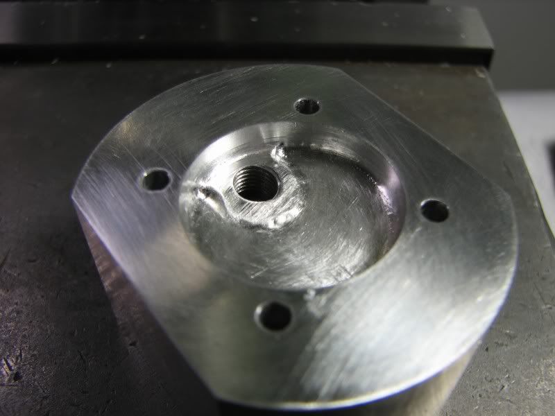
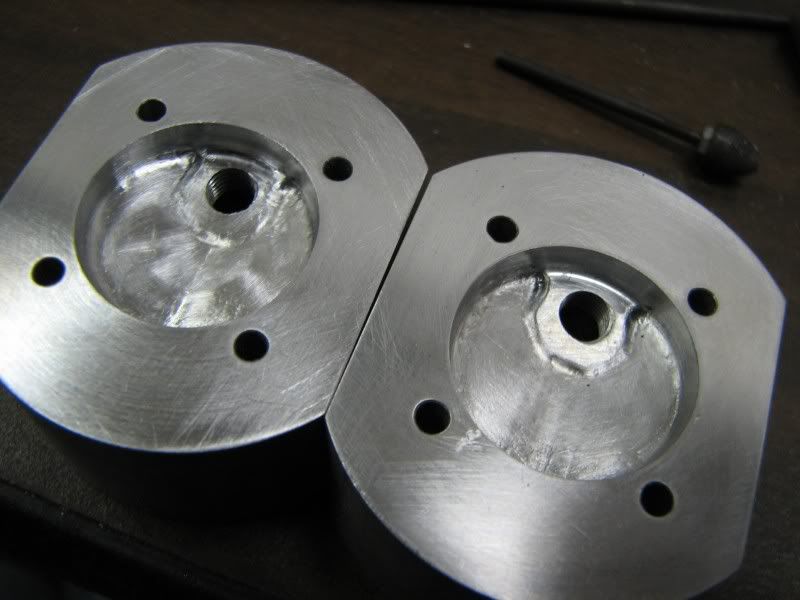
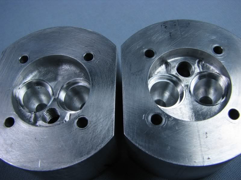
Here's a shot of both of the heads with the chamber machining finished.
HV.jpg


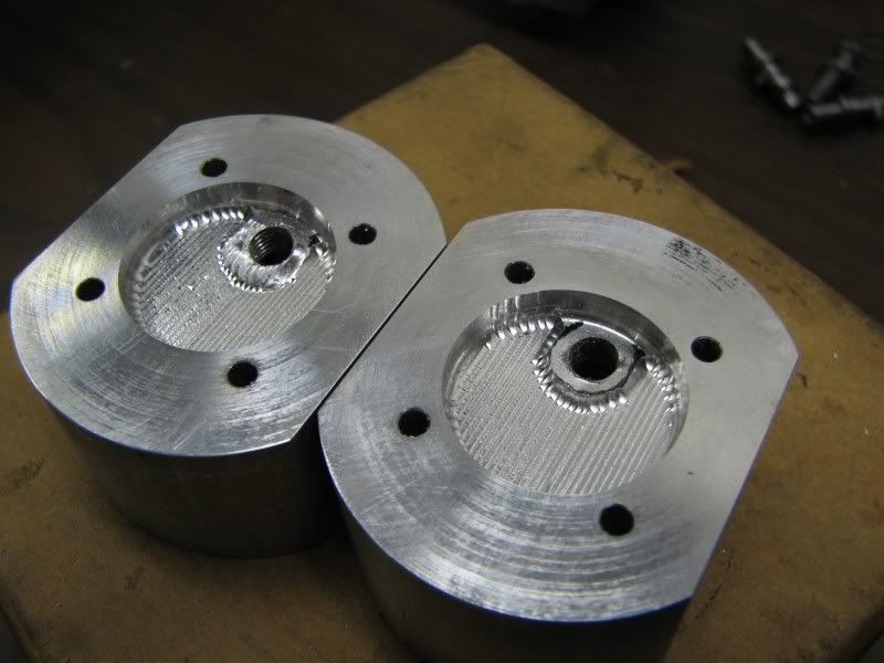
Now it was time to start the hand work, filing, stoning and polishing. The first picture shows the starting procedure, I cover everything with marker ink so I can see where the high spots are when I'm removing stock.
HY.jpg


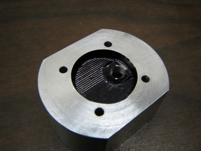
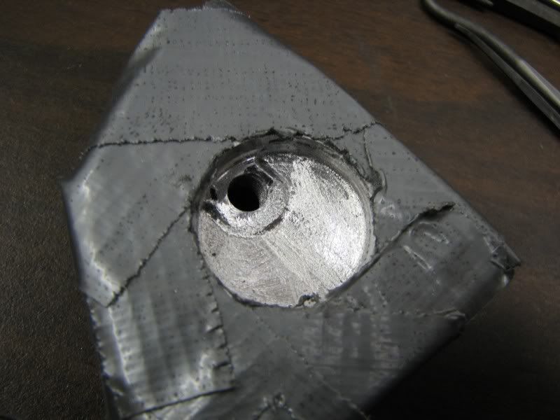
The next picture shows the start of the metal removal. I put a layer of duct tape over everything so that when I bump the head face with the grinder collet I won't put any deep gouges in it, at least not deep enough that I can't take a light cut to clean it up.
You can see the high spots showing as I file across them.
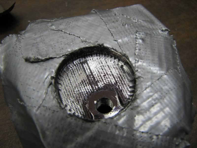
HZ.jpg


Next is a picture showing all the filing finished and the stone work to remove the small bumps in the corners where I can't file.
HW.jpg


The last couple of shots show the finished combustion chamber sanded and polished out and both heads completed.
gbritnell
HX.jpg

JA.jpg
 
Thanks for the update, George. There's a lot of work in those holes!
A good tip, using the duct tape.

Dean
 
I wish some of you guys lived closer ;D Those are pretty George!!
 
Very nice, George.

How do you sand in a cavity like that? Calibrated finger tip?
 
I have several pieces of hardwood sticks, some flat, some with radii and some rounded on the end. I wrap a piece of emery around each stick and proceed to sand. Nothing scientific just plain old elbow grease.
George
 
there is a lot of work in the head that could be avoidable, obviously without ending with that particular shape
so, there must be a reason to do it in this way: is it to have a spark plug that is about in the middle of the combustion chamber, so that the combustion itself could be better?
and the perimeter, the circumference?
why is it better if it is rounded instead of plain?
maybe something that has to do with the 'squish' to promote turbulence in the charge?

anyway, every part that you make is really plenty of care :bow:
 
The simplest reason is the valve centerlines go from the center of the camshaft up to the rocker arms which is about 8 degrees from centerline so therefore the valves need to be canted at that angle so the pushrods push in a straight line. This necessitates that the roof of the combustion chamber be canted at that angle so the valves are square to that surface. On Jerry Howell's V-twin he uses 2 cams per cylinder which allows the pushrods to go straight up to the valves. Believe me it certainly would have been easier that way but I didn't want to copy his design.
gbritnell
 
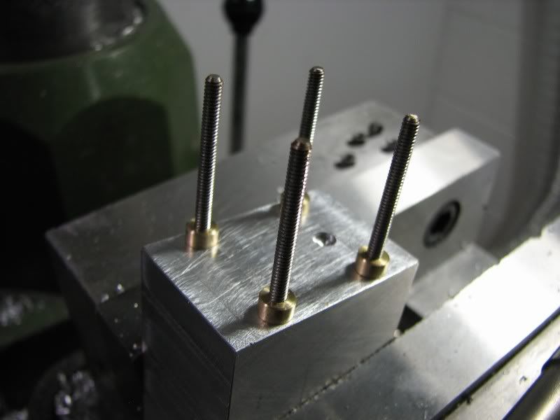
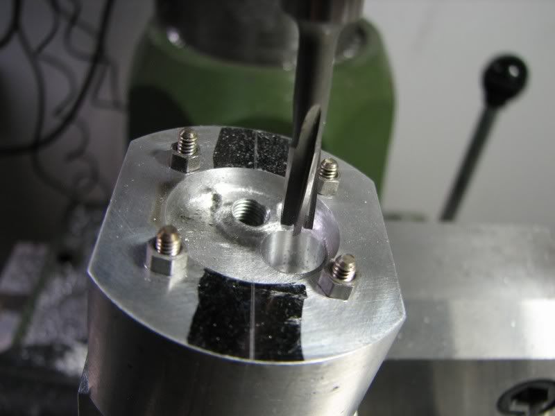
Here's today's efforts. First up I had to make a bushing for a drill to drill an undersized hole for the .187 valve guide hole. All of the tools that I would be using for this operation were relatively short and I didn't want to put a drill chuck in. As a lot of fellows have found out, valve guide to valve seat concentricity is very important and with the mill/drill machine you don't want to have to move anything once you are set up. I had made the holding fixture last week but didn't have any 5-40 screws long enough to hold the head down plus I needed some bushings to locate in the counterbores so I cut up some stainless threaded rod for the job.
JK.jpg


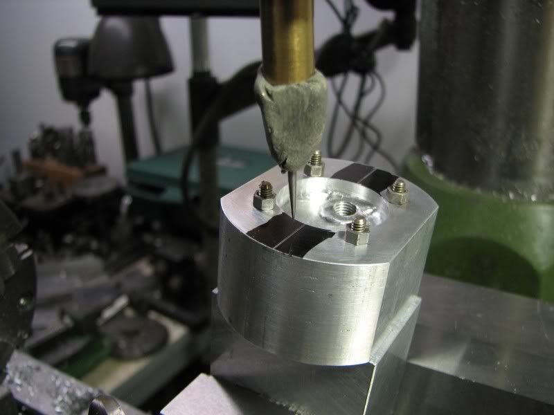
With the head securely bolted down I used the old fashioned wiggler, a piece of modeling clay and a phonograph needle. Here again I didn't have the head space to use my regular wiggler.
JB.jpg
 
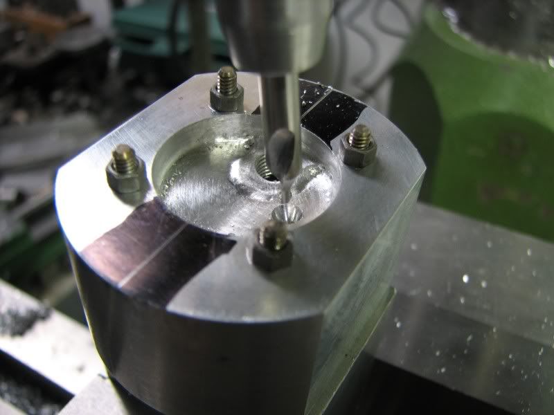
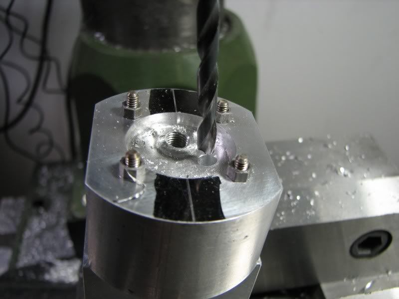
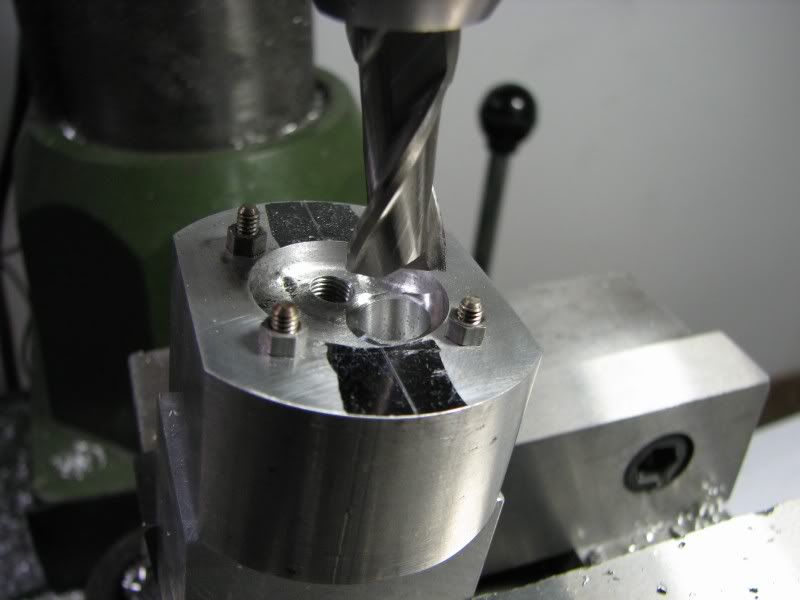
The next steps were center drilling and drilling the undersized hole that I mentioned earlier.
JC.jpg

JD.jpg


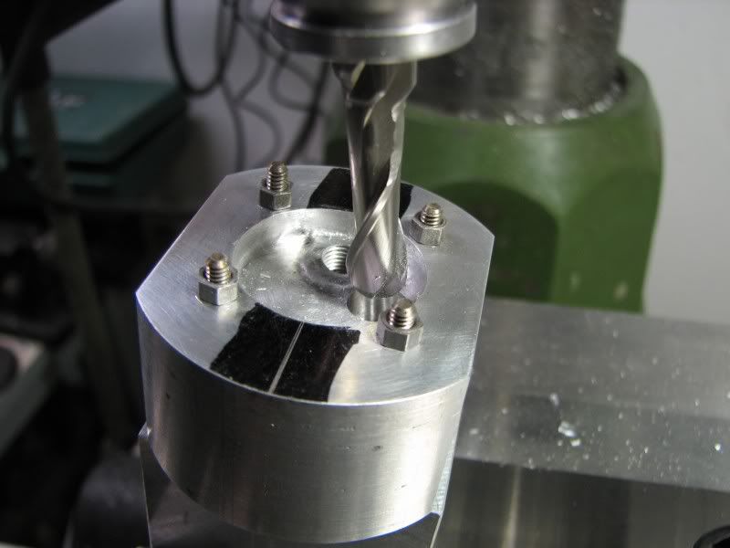
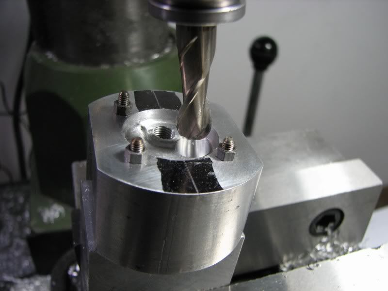
The ports on this head are .375 diameter so I first went in with a .312 ball mill and stayed .01 shy of the depth. This was followed with the .375 ball mill to depth. I used a ball mill to give the port a rounded top. When I come in from the end of the head it will give me a nice radius where the two come together.
JE.jpg

JF.jpg
 
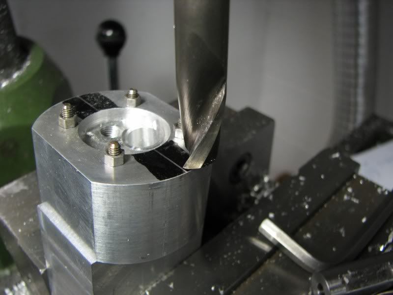
The next tool is a .187 diameter jig mill. For those who aren't familiar with this tool, it is a short rigid cutter with somewhat of a reamer end on it. It is bottom cutting and is used for machining accurate dowel holes. I didn't want to use a reamer for fear that if the hole were the tiniest bit off I would have trouble seating my valves, and the length thing comes into play again.
JG.jpg


Now I went in with a .50 diameter end mill and cut down just enough to spotface the area around the valve seat. The valve seat inserts will be .46 diameter and I will need a square edged hole to get them started straight. The last operation was to go in with the .46 diameter end mill and cut the valve seat pocket to the right depth. I moved off center the radius of the end mill, .23, and came down till the cutter just nicked the head face at the centerline. This would establish my depth starting point. The area that I touched will be machined off later anyway. Now that my depth was set I went back to my center readings on the digitals and cut the seat pocket.
JH.jpg

JJ.jpg


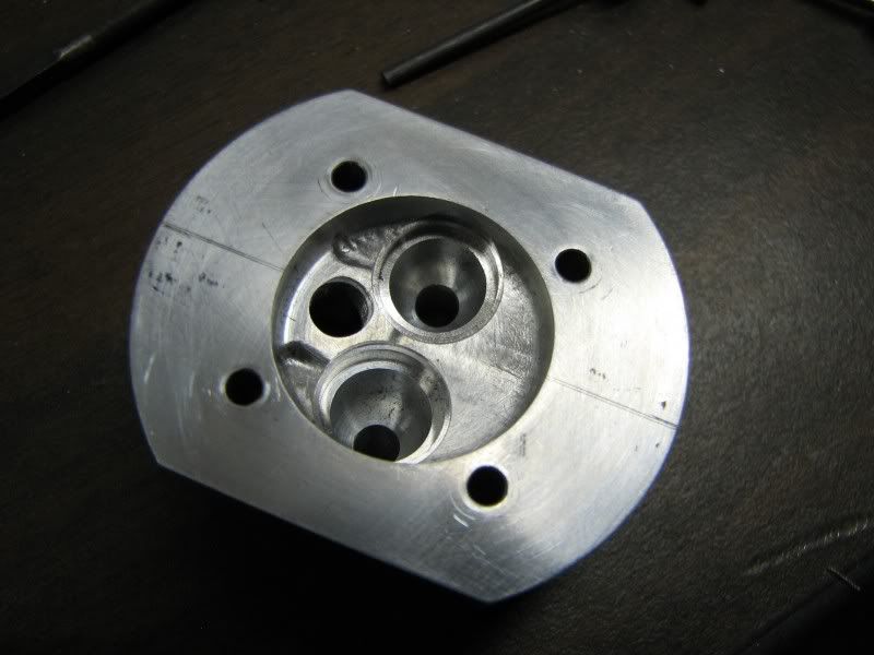
And the last two pictures are the finished valve pockets and seat.
JL.jpg

JM.jpg


George,

You have the patience of a saint - beautiful work as usual :bow: :bow:

Best Regards
Bob
 
You sure work well in close quarters, George. The holes/bores are almost like people crowded into an elevator, shoulder to shoulder.
Looks very professional. Thank you once again, for sharing.

What are you using for the valve seat inserts? Brass?

Dean
 
Thanks guys, Dean the seats will be made out of cast iron.
George
 
George,

I look forward to your posts every day. What a fantastic build and if I just learn a fraction of what you present here (and all your tutorials, etc.) I've come a long way in improving my skills.

Thank you for the extra efforts to photograph and document then share... :bow: :bow: :bow:

Jeff
 
George, you continue to amaze me with your skill and patience.

Chuck
 
George,
Where can I buy jig mills? MSC's search engine draws a blank. Are they also called rose reamers?
RKlopp
 
Rklopp, my cutters are made by Weldon. I bought them from our tool supplier when I was still working. I would think that any over the counter tools supplier would have a Weldon tool catalog. They also go by the names of jig mill, jig borer and jig reamer.
gbritnell
 

Outstanding work, George.

In view of the many superb photographs, discussion, drawings, do we see an article for MEB or HSM here ;D

Best regards, Mati
 
Back
Top