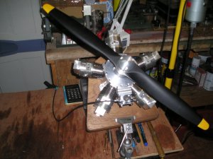
5 cyl OHC Radial.

Home Model Engine Machinist Forum

Help Support Home Model Engine Machinist Forum:

This site may earn a commission from merchant affiliate links, including eBay, Amazon, and others.
Peter,
So far I found no adverse running effects of the equally-spaced link rod pins in the master rod. The drawing of the cylinder liner ( the Robert Sigler version) specifies trimming of the liner top to achieve equal CR for all cylinders.
cilinder afdraaien.jpg

I myself adjusted the CR by trimming the piston crowns to the correct height because in case of an error is is easier for me to make a new piston than to go through the elaborate and messy process of making a new liner.
As far as the spark ignition of the original Edwards is concerned: I found proof on the website of the Miniature Engineering Museum Collection that the original Edwards did have spark ignition. I wonder whether Forest made corrections on the position of the link rod pins or that he kept the equally spacing.
originele  edwards.jpg

Either way, it seems worthwile to investigate how the linkrod configuration was arranged in "real " radial engines.
 
Arguably, we are all building real engines.
Radial engines which we may consider to be full size would normally have relatively long slave rods relative to the pcd of the eyes on the matter rod, so the effect of the angles between those eyes would be less pronounced.
It is quite possible to correct ignition timing to match irregular tdc positions by manufacturing magnetos with irregularly spaced points cams.
 
I seem to recall Carl's spreadsheet also calculated relative link rod angles through the motion range. I cant remember if the 'equalized compression ratio' (compensated) layout geometry on the master rod made it slightly better or worse when it comes to link rod angles, specifically potentially interfering with the base of the liner skirt. That's another design consideration over & above the basic layout. Sometimes you see notches in the liner bottom end or the rods sections are minimized, particularly the long strokers. Another example where model & full size engines may not scale to one another in certain respects.

That's a good point about matching non-equal ignition timing requirements on the distributor or equivalent.
 
When I built my Radian I was not aware of any such problems until I was checking clearances on final assembly, I used shims between the liner and head to provide equal CR to each cylinder but did nothing to correct timing of TDC.
 
Simms motor units produced corrected magneto's for radial engines , unfortunately it was all finished when I joined the diesel development lab a long long time ago.
Brian.
 
Well it's been a long time again shop work just keeps getting in the way of sitting down at the computer and when I do it's normally
to order things for the radial. however we have now progressed to the point where the engine is in the process of final assembly the carb is fitted I have the coils awaiting the delivery of the ignition kits so it looks like we may get it done this year.

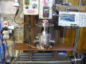
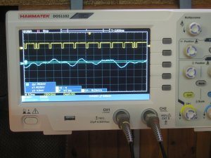
I spent a long time trying to balance the engine by driving it with the mill and measuring the angle and vibration with the scope ' not easy because the natural frequency of the rubber mounts i was using interfered with the results but with the help of the Vibe sensor app on the mobile i was able to com to what i hope is is a good result I have a vibe period at about 1200 rpm but when you drive through that It's down to a reasonable buss but time will tell.
 

Attachments

  • P1013957.JPG
    P1013957.JPG
    336 KB
  • P1013958.JPG
    P1013958.JPG
    223.3 KB
  • P1013976.JPG
    P1013976.JPG
    244 KB
Last edited:
10 minutes ago
Well it's been a long time again shop work just keeps getting in the way of sitting down at the computer and when I do it's normally
to order things for the radial. however we have now progressed to the point where the engine is in the process of final assembly the carb is fitted I have the coils awaiting the delivery of the ignition kits so it looks like we may get it done this year.

I spent a long time trying to balance the engine by driving it with the mill and measuring the angle and vibration with the scope ' not easy because the natural frequency of the rubber mounts i was using interfered with the results but with the help of the Vibe sensor app on the mobile i was able to com to what i hope is is a good result I have a vibe period at about 1200 rpm but when you drive through that It's down to a reasonable buss but time will tell.

Attachments
  • P1013957.JPG
    P1013957.JPG

    336 KBViews: 0
  • P1013958.JPG
    P1013958.JPG

    223.3 KBViews: 0
  • P1013976.JPG
    P1013976.JPG

    Well it's been a long time again shop work just keeps getting in the way of sitting down at the computer and when I do it's normally
    to order things for the radial. however we have now progressed to the point where the engine is in the process of final assembly the carb is fitted I have the coils awaiting the delivery of the ignition kits so it looks like we may get it done this year.

    I spent a long time trying to balance the engine by driving it with the mill and measuring the angle and vibration with the scope ' not easy because the natural frequency of the rubber mounts i was using interfered with the results but with the help of the Vibe sensor app on the mobile i was able to com to what i hope is is a good result I have a vibe period at about 1200 rpm but when you drive through that It's down to a reasonable buss but time will tell.
 
Oops can someone remove the extra posts Finger trouble again .
Thanks Brian H
 
Its been a long time again but the engine is almost ready to go all it needs is a oil tank non return valve (due in 2 days time)
and a can of fuel.
 

Attachments

  • P1013997.JPG
    P1013997.JPG
    337.1 KB
After a lot of fiddling with the mixture and going over valve and ignition timing. IT RUNS the mixture requires further attention and the oil system jet has to be smaller. but it has no vibration after all my fears about that.

Run time is 30 mins in two sessions.
run 1.JPG
run3.JPG


Video to follow Brian.
 

Attachments

  • run2 (2).JPG
    run2 (2).JPG
    246.2 KB
Beautiful work!

May I ask what you were adjusting between runs? I wasn't sure the goal of the different runs.

I can see you have done things very carefu)y and very thorough. Congratulations!

Carl
 
Hi Carl
Thank you for your question
. I was adjusting the mixture screw to make the mix richer , Note that the engine ran on its initial prime from the pump at the rear of the carb but then stopped , I gradually increased the mix until the motor ran evenly then ran it for 15 minuets. THen stoped it for inspection and allowed it to cool
It then then ran for a further 15 min. I now have to reduce the volume of the oil supply and do more work on the mixture.
Thank you again for asking it's important if you don't know to ask.

Brian.
 
Back
Top