- Joined
- Jan 17, 2009
- Messages
- 887
- Reaction score
- 82
Hi Chaps
This is going to be a bit of a long post but thought I'd bring you up todate with my latest short term project, so I'll apologise in advance.
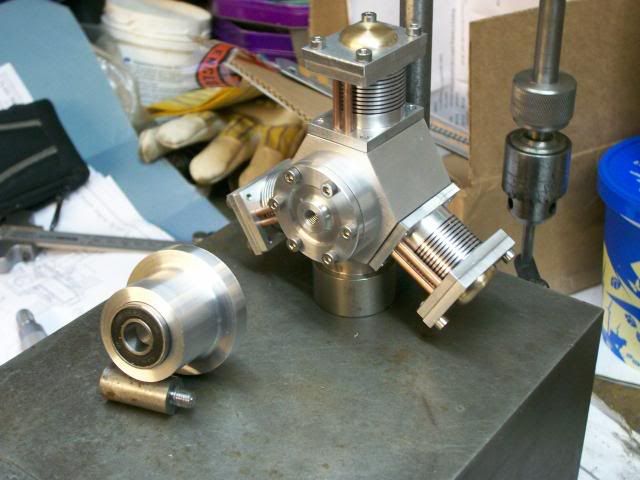
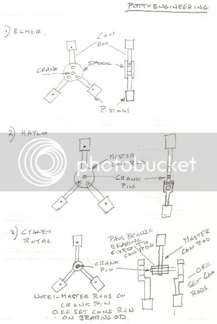
Any way at Model engineering exhibitions I've alway marveled at the models of radial aircraft engines, now this isn't going to be a petrol engine, but it going to be based on two design of model radial steam engines, I'm going to try and take what I think are the best parts in terms of good design and ease of manufacture from these two designs, plus a bit of bling so that they represent an aircraft engine (cooling fins on the cylinders)
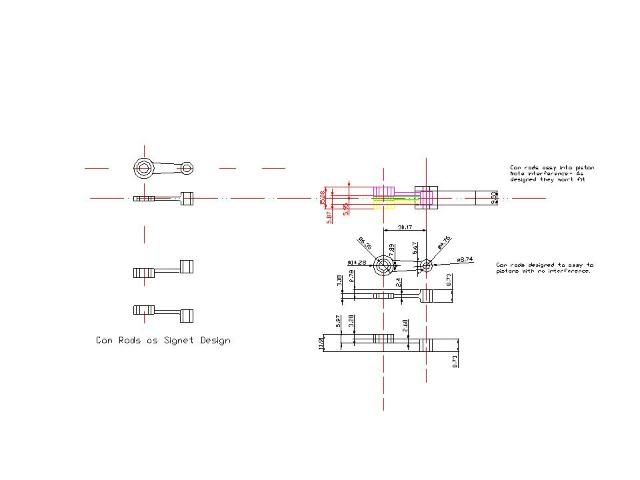
The two design I'm going to work with are:-
The Cygnet Royal by Edgar T Westbury, I got my drawing free from Model Engineer but you can buy them from http://www.myhobbystore.com I understand that you can buy a set of castings for this design but I'm going to use bar stock.
Elmers Radial Engine drawings are available on John Tom http://www.john-tom.com/ElmersEngines/11_Radial.pdf
I've been planning this build for some time slowly putting my ideas together and doing a bit of research and I've started on a set of metric drawings as all my kit is metric, and to get round me the material and tools required.
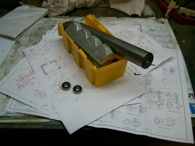
2" dia ally * 250mm length came from ebay, the rest of the stuff came from my stash or as is the case of the chunk of sash weight cast iron from John, and the bearings were donated by Dave Bluchip
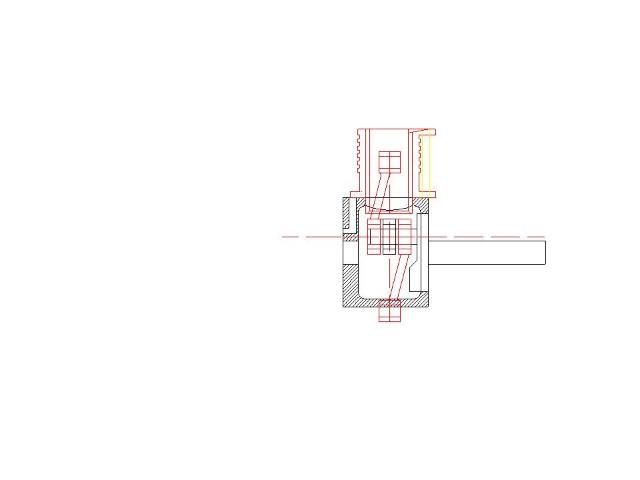
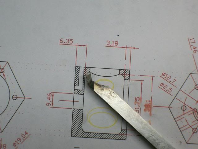
To make the boring bar for the crank case I copied out the sectioned drawing at a 1 - 1 scale and used this as a guide to grind the bar, and yes I know its the wrong way but I'm going to run the lathe in revers as its easy to see what's going on that way.
This is it ground up
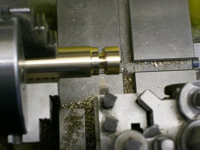
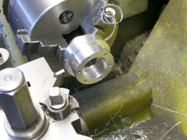
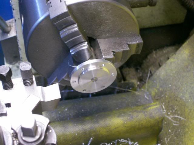
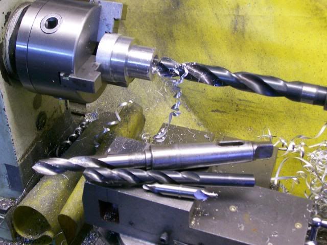
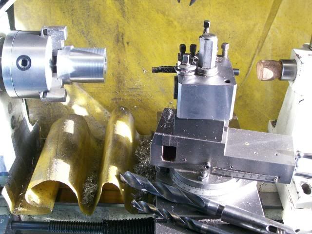
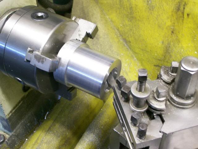
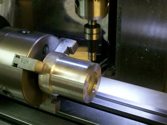
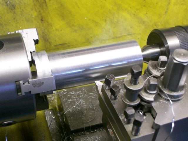
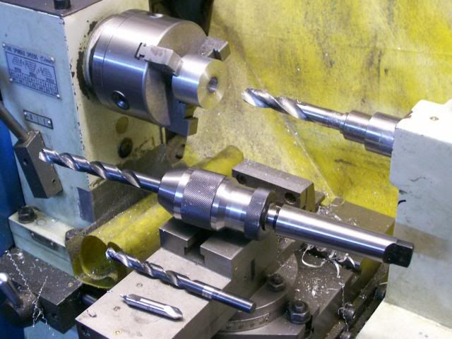
Then with a chunk of ally in the lathe a start was made on the crank case, skim up the OD, centre drill then a series of drill, and then with a boring bar it was roughed out.
Finished off the bore and then brought everything to finished size, Home made boring bar worked fine, although I had to trim a bit more off it to keep it clear of the job.
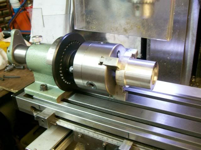
Keeping the job in the chuck the whole lot was transfered to the indexer.
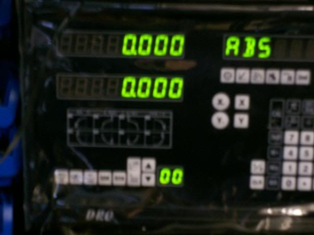
First job with a wobbler find the edges of the job:- zero the X on centre line and zero the Y on the front edge.
With the fly cutter I then made the round bar into an hexagon, this is where table stops help, with the stops set I had no worries about running into the chuck.
Forgot to take a pic of the fly cutting but you've seen that before.
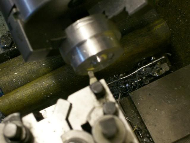
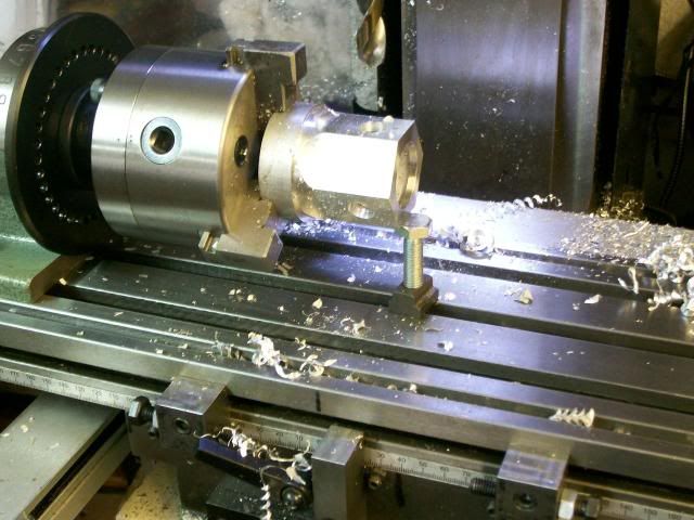
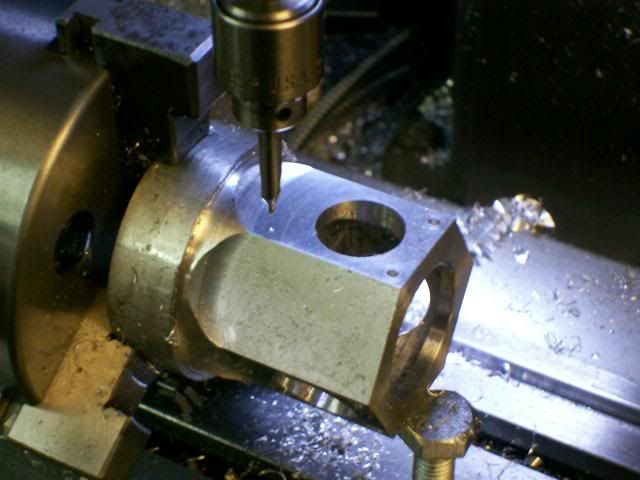
Move the Y to where the cylinders will be mounted and zero the dro again from know on all features will be from the centre line of this hole.
Centre drill then roughing drill to get the meat out. Note use of support Jack
And then with the boring head rough out all the to within 0.5 mm
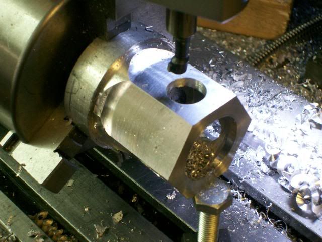
With all the cylinder holes rouged out, brought the first one to size, then as I wanted all to be the same, it'll make things easy down line, the boring bar was clamp up and the other two finished at the same setting.
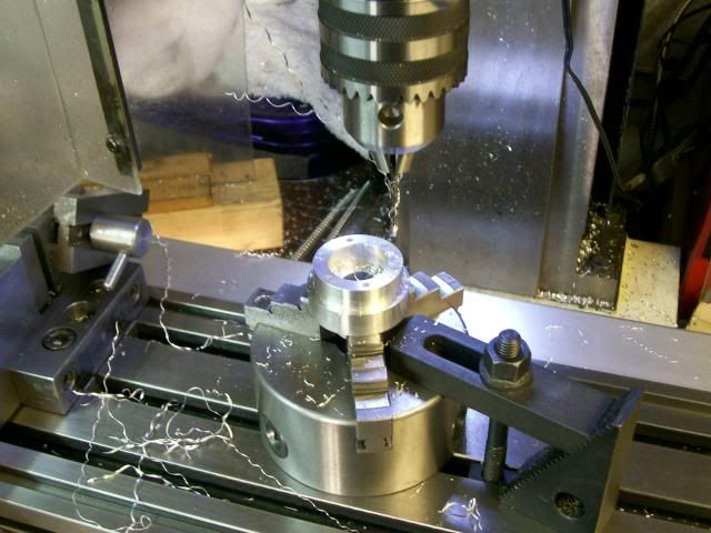
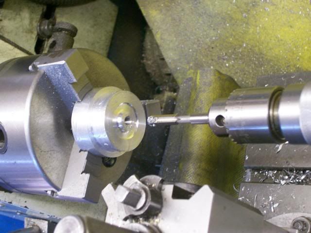
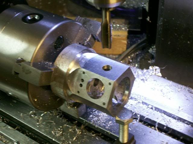
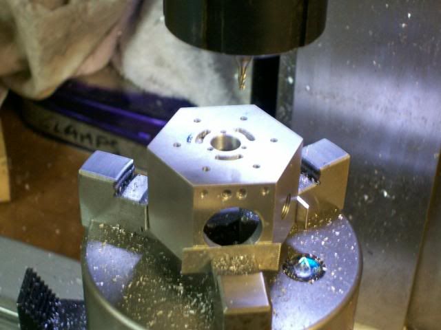
One of the reasons I've reproduced the drawing in cad was that I wanted all the holes dimensioned from the centre line of the cylinders this way I can make best use of the DRO, so to drill the holes move the table to the x and Y location drill the hole, rotate the spin indexer drill the same hole in the other face, spin index drill the same hole in the third face reposition the table x and Y etc etc
Like this
And here we are with all the holes drilled in the horizontal position including the breather hole tapped 3/8*40 ME I'll tap the M3 holes on my tapping table.
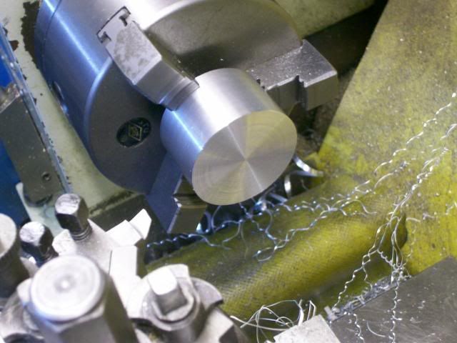
With the job parted off I set it up in the chuck to face it off to length, when disaster struck, the @£$%%^&* thing flipped out of the chuck putting a few dings in it, luckily they are in places that won't be seen when its all assembled together, so set it up in the mill vice to fly cut it off to length.
Now for the port face:-
A little bit more setting up required for this.
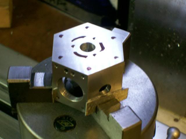
First as it will be easy to put features in the wrong orientation, I marked the job up where things were to go checking and double checking I'd got it correct, it wasn't accurately marked just enough to keep me on the straight and narrow.
Next get the job on the RT centre line, to do this you rotate the RT, as I was using a three jaw self centre chuck I had to keep channing the position of the job in the chuck and tightening up on different jaws to find the best place I got it to 0.1mm run out well fit for function.
Next I had to get the hexagon in the correct orientation by clocking up a face level with the RT on zero.
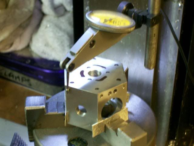
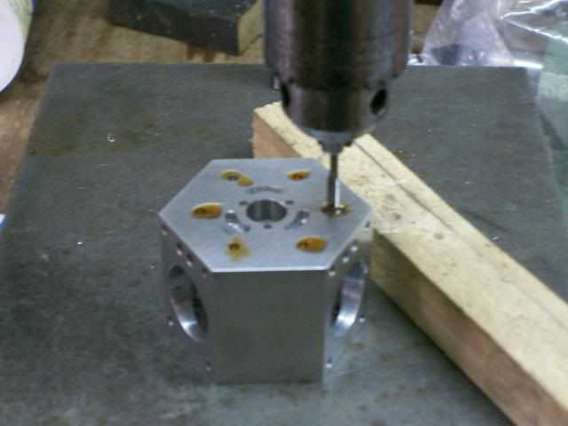
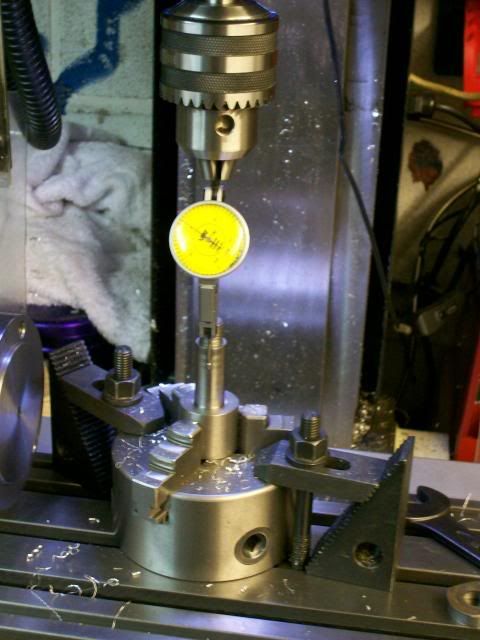
Then get the job on the centre line of the quill (spindle) to do this you hold the DTI in the spindle and rotate the spindle.
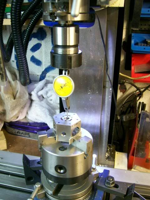
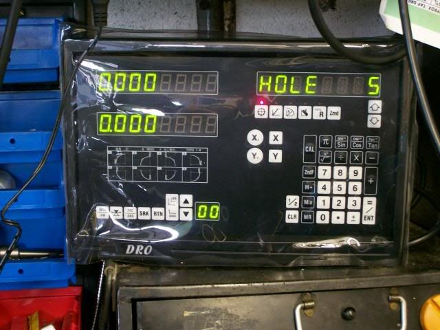
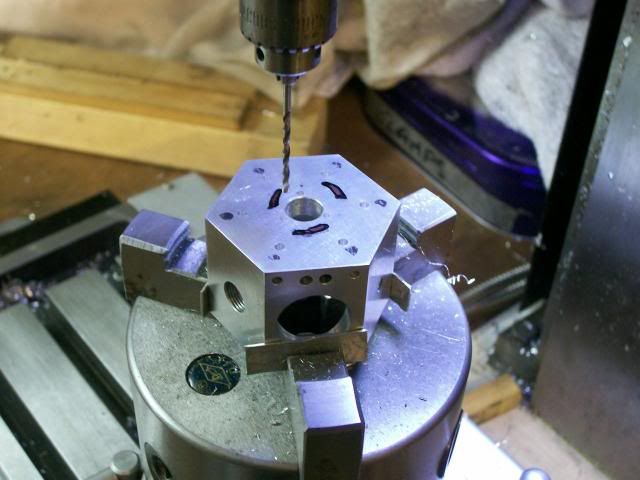
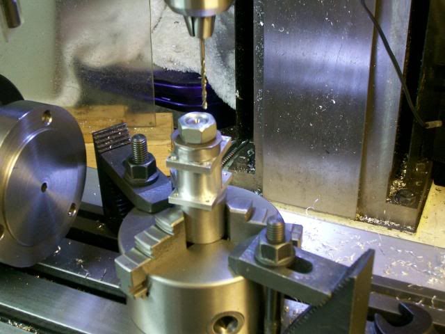
Then use the DRO drill the holes in this case one set of 6 and one set of 3.
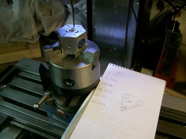
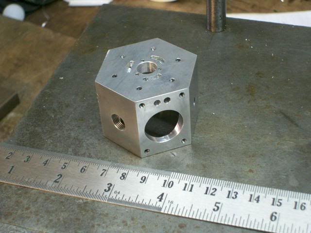
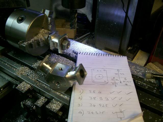
Ok last bit of work on the crank case:- cut the steam galleries, the drawing calls for the angle from edge to edge to be 60 deg, but for machining the critical feature is centre to centre of the cutter I'm using a 2mm slot drill so drew it up in cad and checked the cutter centre to centre angle 44 deg.
The mill was still set on the centre of the job, move the radius distance to where the ports will be, and rotated the RT 30 deg then off set 1mm to allow 1/2 cutter dia. lower the cutter 1 mm into work and rotate RT 44 deg. To make things simple I worked out the movement of the RT in advance and wrote out a crib sheet.
Like this
Ports cut
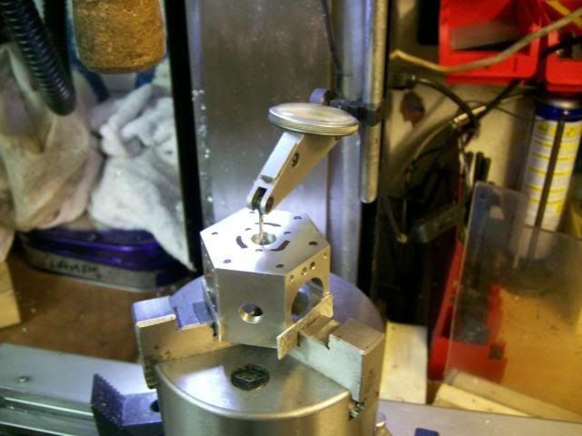
Last job tap all the holes:- I used my home made tapping stand, so that they were all tapped nice and square.
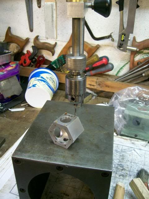
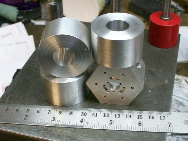
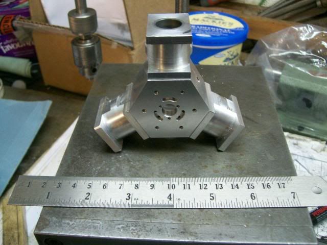
And there we are Crank case done.
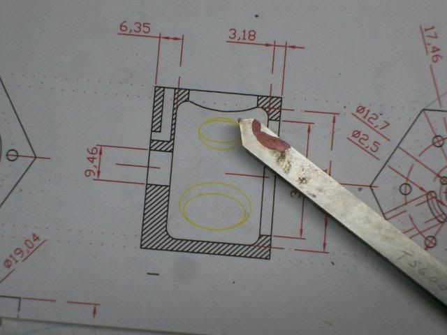
The cylinders I'm going to make from ally with cast iron liners.
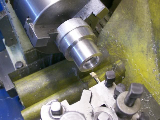
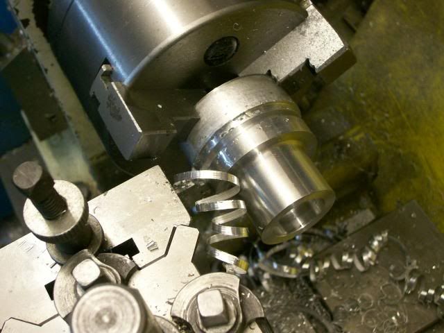
2" diameter length of ally being turned down.
I was hopping to get four cylinders out of this ally (one spare) but I forgot about the width of the parting tool so only got three, I'll have to be real carful
When making multiples its important to get certain key feature as near as posable all the same size, in this case its the width and the bore dia.
So by putting the job hard up against the back of the chuck and zeroing up the cross slide they were all faced off the same length.
Because of how I'm going to machine things down line I'm not particularly worried about getting the bore concentric with the OD. So sticking the blanks back in the chuck all the bores were centre drilled and drilled out with bigger and bigger drills.
They were all then rough out to within 1/2 mm of finish size with a boring bar.
Then finished off to size with the boring bar:- one after the other at the same setting, running the final cut through a couple of times to take the spring out of the bar.
For length they were all within 0.05mm and for dia 0.02 mm thats well fit for purpose.
Here they all are.
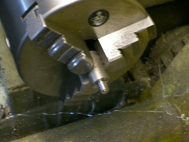
Having slept on it I decided to take some of the meat off the cylinders before I made the liners.
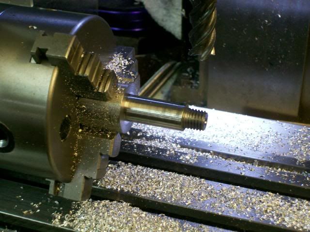
So first job turn up a mandrel thats a nice slide fit on the cylinders with a M12 thread.
Like this
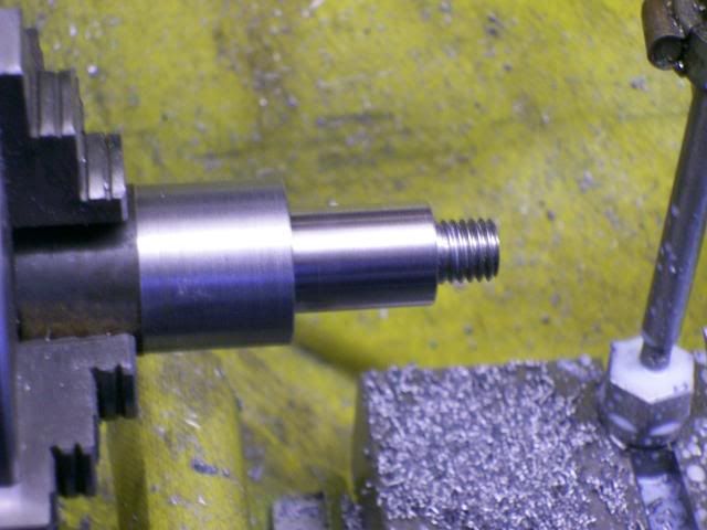
This required some quite heavy cuts and I was a bit concerned the liner would come lose, so decided to get rid of quite a bit of the unwanted material before fitting them.
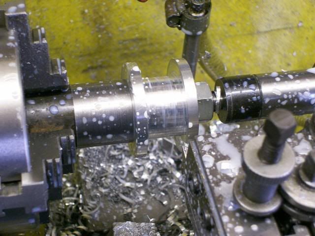
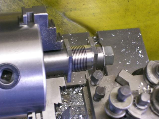
Then turn down the 35 mm dia sash weight down to 19.25 to give a 0.02 mm interferance fit in the cylinder and part off to length.
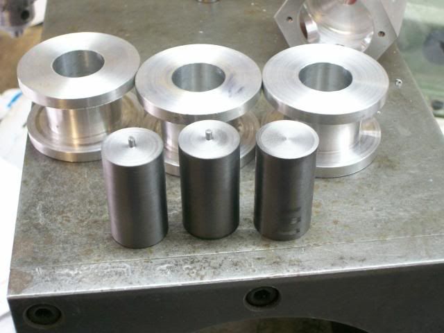
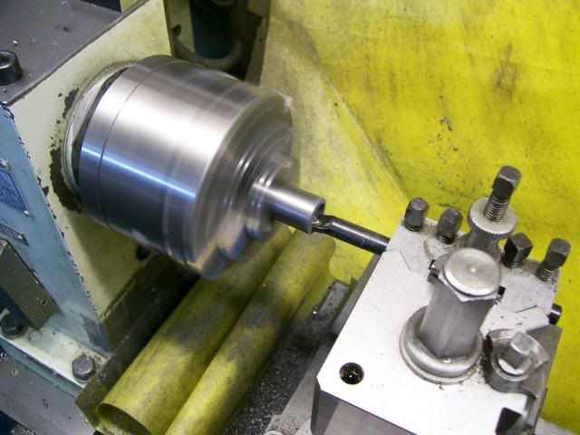
Then set back up in the lathe, again concentricity with OD not that important, centre drill and with increasing in diameter drill rough all three out, then they were set back up to finish with boring bar at the same cut so they all ended up the same size.
As I'm going to use the mandrel again to finish off the machining its easyer if they all have the same size bore. The actual size of the bore is not that important, I'll just make the piston to fit, its easy to work to an accurate OD than it is a ID, what's important with the bore is that its parallel and the finish is reasonable.
I just gave the liners a polish to give them a square start into the cylinder, then with a bit of high strength loctite they were squeezed together using the vice as a press.
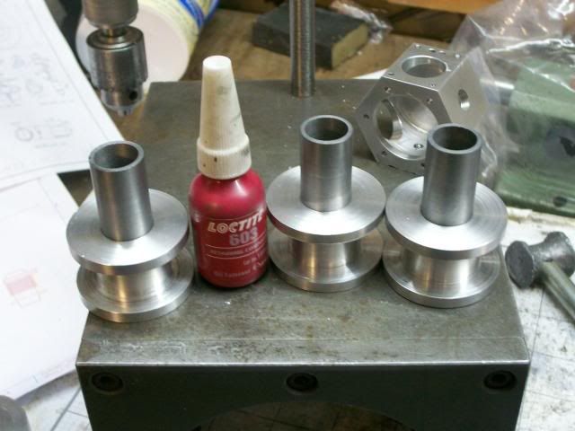
And her we are all three liners assembled to the cylinders.
I give the loctite 24 hrs to cure before I do any more machining to the cylinders
Set the mandrel back up in the lathe and turned it down to a nice fit on the sleaves, this is why I wanted all the bores the same size, so that one mandrell can be used for all three.
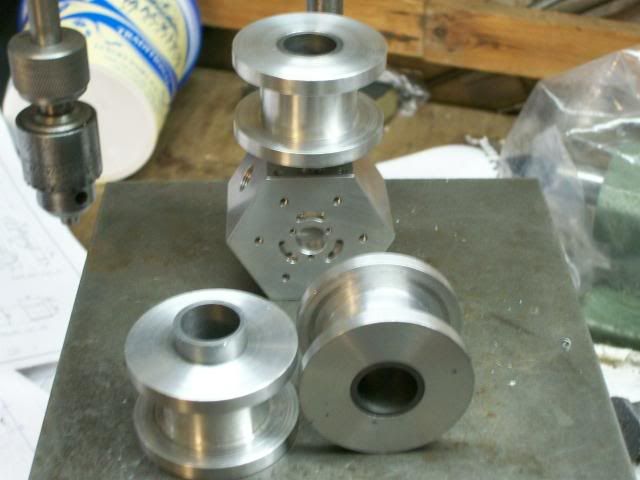
Then same trick as before:- chuck taken off the lathe with the mandrell still in place and fixed on the Spin Indexer.
Her we have one in the indexer with my crib sheet and two assy in the crank.
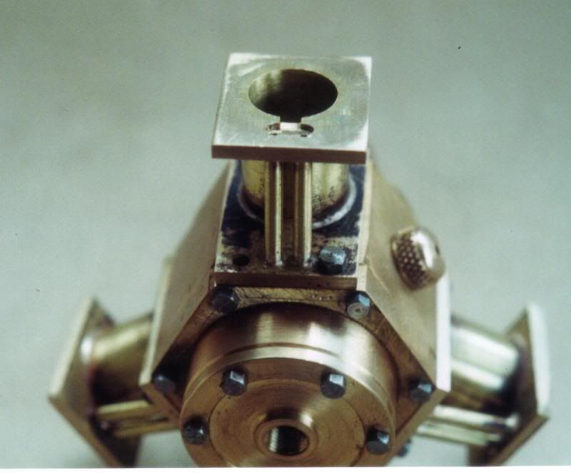
Close up of three in the crank case,
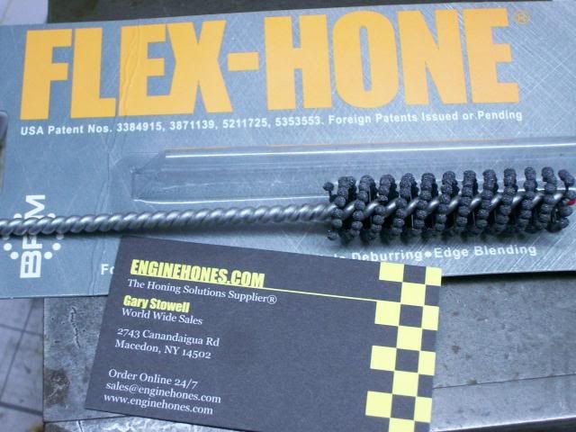
Just taken delivery of this from the US, I saw these in use a few years ago at one of our subcontractors, he was using a big one 6" dia to hone the bores of some hydrolic cylinders, have any of you guys ever used them and have you any tips.
Keeping the mandrell still in the chuck set it up on the mill and centred the mill quill on the mandrell zeroed the DRO.
Then just as with the crank case indexed and drilled the fixing holes for the cylinder.
With most of the key features machined in the cylinder time for a bit of bling.
Again still keeping the mandrell in the chuck it was transfered over to the lathe, then with one of Johns finning tools some fins were added to the cylinder.
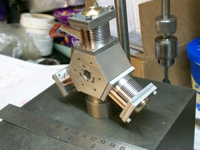
I was going to use some 4mm brass tube for the air ways but the gap between the two pipes would only have been 0.75 mm so I bottled out of that and decided to use 1/8" copper tubes, did a lose assembly to see how the bling would look.
That doesn't look too bad, and I was realy pleased how the cylinders holes lined up with the crank case, this was all due to the accuracy I got out of the DRO, without out it I would have resorted to opening out the holes a fiddling arround to get things to assemble correctly.
Cheers
Stew
This is going to be a bit of a long post but thought I'd bring you up todate with my latest short term project, so I'll apologise in advance.
Any way at Model engineering exhibitions I've alway marveled at the models of radial aircraft engines, now this isn't going to be a petrol engine, but it going to be based on two design of model radial steam engines, I'm going to try and take what I think are the best parts in terms of good design and ease of manufacture from these two designs, plus a bit of bling so that they represent an aircraft engine (cooling fins on the cylinders)
The two design I'm going to work with are:-
The Cygnet Royal by Edgar T Westbury, I got my drawing free from Model Engineer but you can buy them from http://www.myhobbystore.com I understand that you can buy a set of castings for this design but I'm going to use bar stock.
Elmers Radial Engine drawings are available on John Tom http://www.john-tom.com/ElmersEngines/11_Radial.pdf
I've been planning this build for some time slowly putting my ideas together and doing a bit of research and I've started on a set of metric drawings as all my kit is metric, and to get round me the material and tools required.
2" dia ally * 250mm length came from ebay, the rest of the stuff came from my stash or as is the case of the chunk of sash weight cast iron from John, and the bearings were donated by Dave Bluchip
To make the boring bar for the crank case I copied out the sectioned drawing at a 1 - 1 scale and used this as a guide to grind the bar, and yes I know its the wrong way but I'm going to run the lathe in revers as its easy to see what's going on that way.
This is it ground up
Then with a chunk of ally in the lathe a start was made on the crank case, skim up the OD, centre drill then a series of drill, and then with a boring bar it was roughed out.
Finished off the bore and then brought everything to finished size, Home made boring bar worked fine, although I had to trim a bit more off it to keep it clear of the job.
Keeping the job in the chuck the whole lot was transfered to the indexer.
First job with a wobbler find the edges of the job:- zero the X on centre line and zero the Y on the front edge.
With the fly cutter I then made the round bar into an hexagon, this is where table stops help, with the stops set I had no worries about running into the chuck.
Forgot to take a pic of the fly cutting but you've seen that before.
Move the Y to where the cylinders will be mounted and zero the dro again from know on all features will be from the centre line of this hole.
Centre drill then roughing drill to get the meat out. Note use of support Jack
And then with the boring head rough out all the to within 0.5 mm
With all the cylinder holes rouged out, brought the first one to size, then as I wanted all to be the same, it'll make things easy down line, the boring bar was clamp up and the other two finished at the same setting.
One of the reasons I've reproduced the drawing in cad was that I wanted all the holes dimensioned from the centre line of the cylinders this way I can make best use of the DRO, so to drill the holes move the table to the x and Y location drill the hole, rotate the spin indexer drill the same hole in the other face, spin index drill the same hole in the third face reposition the table x and Y etc etc
Like this
And here we are with all the holes drilled in the horizontal position including the breather hole tapped 3/8*40 ME I'll tap the M3 holes on my tapping table.
With the job parted off I set it up in the chuck to face it off to length, when disaster struck, the @£$%%^&* thing flipped out of the chuck putting a few dings in it, luckily they are in places that won't be seen when its all assembled together, so set it up in the mill vice to fly cut it off to length.
Now for the port face:-
A little bit more setting up required for this.
First as it will be easy to put features in the wrong orientation, I marked the job up where things were to go checking and double checking I'd got it correct, it wasn't accurately marked just enough to keep me on the straight and narrow.
Next get the job on the RT centre line, to do this you rotate the RT, as I was using a three jaw self centre chuck I had to keep channing the position of the job in the chuck and tightening up on different jaws to find the best place I got it to 0.1mm run out well fit for function.
Next I had to get the hexagon in the correct orientation by clocking up a face level with the RT on zero.
Then get the job on the centre line of the quill (spindle) to do this you hold the DTI in the spindle and rotate the spindle.
Then use the DRO drill the holes in this case one set of 6 and one set of 3.
Ok last bit of work on the crank case:- cut the steam galleries, the drawing calls for the angle from edge to edge to be 60 deg, but for machining the critical feature is centre to centre of the cutter I'm using a 2mm slot drill so drew it up in cad and checked the cutter centre to centre angle 44 deg.
The mill was still set on the centre of the job, move the radius distance to where the ports will be, and rotated the RT 30 deg then off set 1mm to allow 1/2 cutter dia. lower the cutter 1 mm into work and rotate RT 44 deg. To make things simple I worked out the movement of the RT in advance and wrote out a crib sheet.
Like this
Ports cut
Last job tap all the holes:- I used my home made tapping stand, so that they were all tapped nice and square.
And there we are Crank case done.
The cylinders I'm going to make from ally with cast iron liners.
2" diameter length of ally being turned down.
I was hopping to get four cylinders out of this ally (one spare) but I forgot about the width of the parting tool so only got three, I'll have to be real carful
When making multiples its important to get certain key feature as near as posable all the same size, in this case its the width and the bore dia.
So by putting the job hard up against the back of the chuck and zeroing up the cross slide they were all faced off the same length.
Because of how I'm going to machine things down line I'm not particularly worried about getting the bore concentric with the OD. So sticking the blanks back in the chuck all the bores were centre drilled and drilled out with bigger and bigger drills.
They were all then rough out to within 1/2 mm of finish size with a boring bar.
Then finished off to size with the boring bar:- one after the other at the same setting, running the final cut through a couple of times to take the spring out of the bar.
For length they were all within 0.05mm and for dia 0.02 mm thats well fit for purpose.
Here they all are.
Having slept on it I decided to take some of the meat off the cylinders before I made the liners.
So first job turn up a mandrel thats a nice slide fit on the cylinders with a M12 thread.
Like this
This required some quite heavy cuts and I was a bit concerned the liner would come lose, so decided to get rid of quite a bit of the unwanted material before fitting them.
Then turn down the 35 mm dia sash weight down to 19.25 to give a 0.02 mm interferance fit in the cylinder and part off to length.
Then set back up in the lathe, again concentricity with OD not that important, centre drill and with increasing in diameter drill rough all three out, then they were set back up to finish with boring bar at the same cut so they all ended up the same size.
As I'm going to use the mandrel again to finish off the machining its easyer if they all have the same size bore. The actual size of the bore is not that important, I'll just make the piston to fit, its easy to work to an accurate OD than it is a ID, what's important with the bore is that its parallel and the finish is reasonable.
I just gave the liners a polish to give them a square start into the cylinder, then with a bit of high strength loctite they were squeezed together using the vice as a press.
And her we are all three liners assembled to the cylinders.
I give the loctite 24 hrs to cure before I do any more machining to the cylinders
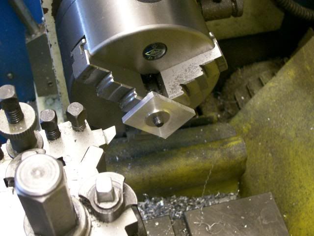
Set the mandrel back up in the lathe and turned it down to a nice fit on the sleaves, this is why I wanted all the bores the same size, so that one mandrell can be used for all three.
Then same trick as before:- chuck taken off the lathe with the mandrell still in place and fixed on the Spin Indexer.
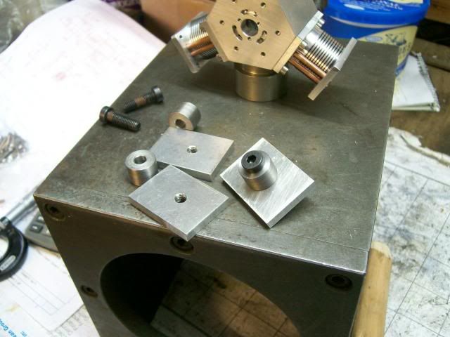
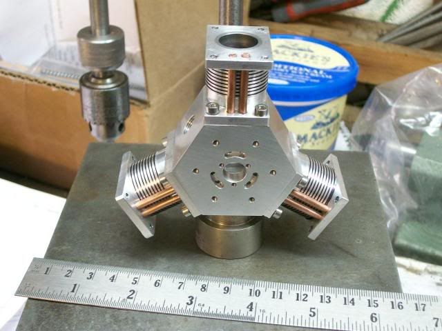
Her we have one in the indexer with my crib sheet and two assy in the crank.
Close up of three in the crank case,
Just taken delivery of this from the US, I saw these in use a few years ago at one of our subcontractors, he was using a big one 6" dia to hone the bores of some hydrolic cylinders, have any of you guys ever used them and have you any tips.
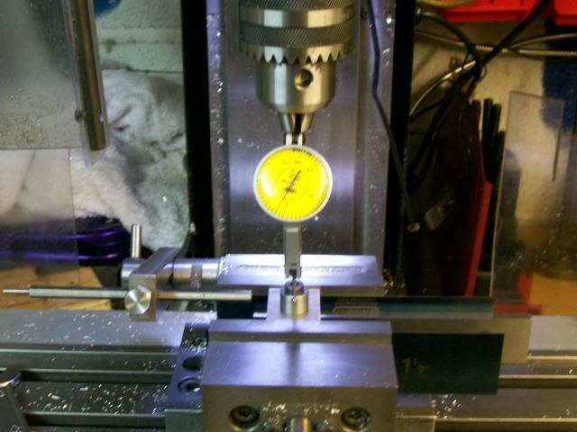
Keeping the mandrell still in the chuck set it up on the mill and centred the mill quill on the mandrell zeroed the DRO.
Then just as with the crank case indexed and drilled the fixing holes for the cylinder.
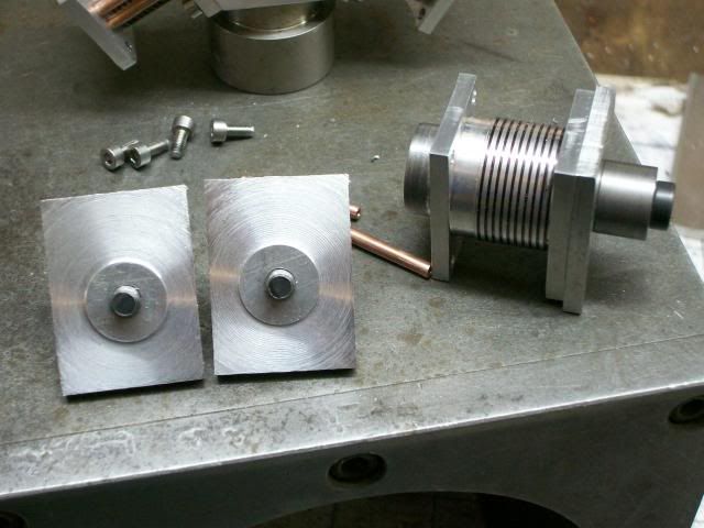
With most of the key features machined in the cylinder time for a bit of bling.
Again still keeping the mandrell in the chuck it was transfered over to the lathe, then with one of Johns finning tools some fins were added to the cylinder.
I was going to use some 4mm brass tube for the air ways but the gap between the two pipes would only have been 0.75 mm so I bottled out of that and decided to use 1/8" copper tubes, did a lose assembly to see how the bling would look.
That doesn't look too bad, and I was realy pleased how the cylinders holes lined up with the crank case, this was all due to the accuracy I got out of the DRO, without out it I would have resorted to opening out the holes a fiddling arround to get things to assemble correctly.
Cheers
Stew


![DreamPlan Home Design and Landscaping Software Free for Windows [PC Download]](https://m.media-amazon.com/images/I/51kvZH2dVLL._SL500_.jpg)


![MeshMagic 3D Free 3D Modeling Software [Download]](https://m.media-amazon.com/images/I/B1U+p8ewjGS._SL500_.png)