Your Home Lathe Tooling

Home Model Engine Machinist Forum

Help Support Home Model Engine Machinist Forum:

This site may earn a commission from merchant affiliate links, including eBay, Amazon, and others.
zeusrekning said:
I have never worked with parts that large. What kind of tolerance was the hole to be held to?
Tim

The 4 foot bore was actually 48.005" +.002 -.000
Slop work compaired to model building!
 
:eek: :eek: :eek: More details. How was it inspected. How do you work your way up to that dimension with out scraping.
 
Well this is getting way off topic, but I KNOW the originator of the thread
doesn't mind! ;)

zeusrekning you reach that size by brute force until you get to within
.100" then it becomes a finesse thing. That same machine that you just
beat the crap out of is expected to cut a perfectly straight finish cut.
It WON'T! Finishing is a series of light finish cuts. It might cut on size
at the top, -.002 in the middle and back to on size at the bottom.
You would calculate that cutting arc in .0005" increments.
as the head was feeding down you would manually "bump" the tool into the
cut .0005" at a time to the center of the bore. From there you would bump
it away from the cut .0005" at a time until you ended up at the beginning
reading. The stock we worked with cost a bit more than what I work with
at home. You DIDN'T want to make an error!

One time we were making a large 8 foot OD brass bushing.
6 people had already told me that the casting cost $47,000
I said if one more person reminded me of that I'd part the damn thing in half.
A 5 minute break to the locker room resulted in SOMEONE taking a yellow
paint marker to it. The bold bright writing read:
"RICK I COST $47,000 DON'T F&*% ME UP!"
I never did find out who had added those little words of encouragement. LOL

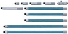
We have a tubular inside mic set manufactured by Mitutoyo.
It's measuring rage is from 40" to 160"
It looks very much like this.
137-205.jpg

It's checked for calibration using only the 40" assembly against an inspected
40" Mitutoyo Outside Mic.
For any size with a tolerance of .005 or less it's readings are verified but checking the
mic with a 60", 84" or 120" vernier caliper. Yes we DO have Mitutoyo Vernier Caliper
that will measure up to 10 feet. It requires 3 people to use it at that distance.
One person holding the "dumb end" one in the middle to give the beam just enough
upward pressure to remove and sag, and the man at the "smart end" taking the
measurement. Everyone there has to know what they are dong to get an accurate
measurement. We're either good at it, or we've been very lucky. We've never had
a large part returned for an errant size.

For anything over 120" we use Pi Tape's
I had a post regarding them here. Pi Tape
We have Pi Tape's that will read up to 15 feet or 180 inches.

I worked on that scale for almost 20 years and then decided to make model engines
at home. I've been a machinst for 30 years, but this scale is a whole different world!

Rick


Good stuff!

I've been reading about this "tool bumping" for some time and actually tried it on my home lathe. I wanted to see if I could improve the accuracy on a long shaft that was getting a little taper if left to it's own ways.

Worked out great!

Best,

BW
 
BobWarfield said:
Good stuff!

I've been reading about this "tool bumping" for some time and actually tried it on my home lathe. I wanted to see if I could improve the accuracy on a long shaft that was getting a little taper if left to it's own ways.

Worked out great!

Best,

BW

I bumped tools for 20 years.
Now I really appreciate a CNC machine.
Their not perfect! They will still taper.
Beauty is if you have a -.003 taper over a 20" length you just adjust the program.
To make it simple if your cutting 1.000 diameter program X diameter for 1.000 at Z 0
and X diameter at 1.003 at Z 20.00 You end up with a perfectly straight fit.
That beats the hell out of trying to manually bump a lead screw .0005 at a time.

At home it's still done the old way.
It feels pretty good when you mic that fit and it's perfect for it's entire length.
It's not the machine that makes that happen, it's the touch of a machinist.

Rick
 
I enjoyed that account - keep em coming! For me the fun is mostly in the solving the puzzle. It's not often i get first hand exposure to 10' dia puzzles so learning how they're solved is always of interest. with those very large measure instruments, how attention was paid to thermal expansion......at 10', 5 degrees of warming up from handling would change the measurement by .003!
 
I'm pretty sure I had posted this picture somewhere here before,
but this is the actual machine that I ran for 20 years at the place I
still work for.
OM1.jpg

The man at the controls is by buddy Duke. I worked opposite him
for that entire time.
That Vertical Boring Mill was manufactured by Osaka Machinery LTD of
Japan in 1973. It's 35 years old and still ready to work hard everyday.
We'd referr to it as a Horse of a Machine.
It has a maximum swing of 177" and 36" or ram travel.
I personally have turned parts on it that weighed just over 32,000 pounds.
I miss running it sometimes, but I DON'T miss the climbing over, under
and inside of parts to do the set up work.
I'm just plain too old for that stuff!

Rick
 
Rake60, that's a real man's toy, what kind of parts do you all make, what kind of business at the parts that you make used in, thanks for the pic's and information, LatheNut
 
The most comman parts, made or repaired on that machine are either
crane/dragline parts or aggregate industry (rock crusher) parts.
Of course there are many other jobs done on it but those two are the
majors.

I've mentioned cutting buttress threads that were 1.032 deep with a
2.000" lead. Those are for rock crashers. We cut both the internal
and external threads for them on that machine.
That machine was not originally designed to thread.
It was an in house venture to fit it with a direct drive gear box to
make that possible. Once the threading gears are engaged they are
not disengaged until the thread is finished. To relieve tool pressures
the saddle is gingerly bumped up and down using the traverse buttons.
Some of the parts we put on that machine were too heavy for the
10 Ton overhead crane. There is an axillary 5 Ton crane on the same
rails. A spreader bar was designed that would place 66% of the lifting
force on the 10 Ton and 33% on the 5 Ton.
We exceeded that at times.
That is acceptable.
You can legally exceed the rated capacity of an overhead crane by 50%
As long as the crane is inspected immediately before and after the lift.

Rick


I bought some parting tools from the guy on Ebay -SAMSWS but his postage costs to the UK were rather high!

samswsno7.jpg


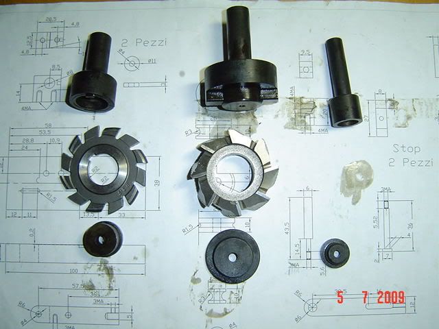
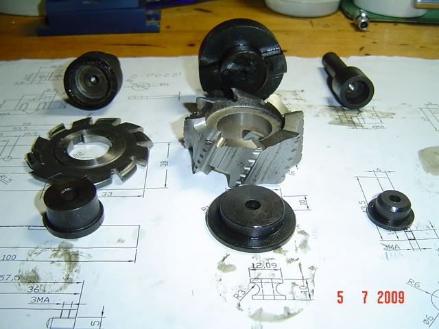
While I was deciding which burner to be used..I made some slitting harbor...I made also one for the Hilmar blade...!! Tommorrow I have to use it for the doing the strip for the second burner on my project!! Noting too difficult..but a present to Hilmar...Thanks again my friend...I'll maintain my promist!!!
DSC02078.jpg

DSC02076.jpg
 

Latest posts

Back
Top