X2 Mini Mill Power Feed

Home Model Engine Machinist Forum

Help Support Home Model Engine Machinist Forum:

This site may earn a commission from merchant affiliate links, including eBay, Amazon, and others.
Hi Pete,
Now mopping up the odds & ends on the a H&M Engine and should be running the engine by this Saturday.
Come next month will start on the mill table feed. DC motor and speed control on hand now. Most likely will be mirror image of your powered mill table feed. Sick and tired of hand cranking table to mill long pieces.

Hi Pete,
Wished I had DIYed the power feed. Was miling a 6 fluke CounterBore while required very long&shallow depth cuts. Now in the midst of building another engine---the Nemett-Lynx which has some tedious milling. I have all the components on hand to build the power feed but have yet to find the time.
 
I have power feed on the X axis of my mill, but may only use it about once per year, I just have a preference for feeding by hand.

Paul.
 
On my Seig-2 mill I always found it almost impossible to get an even 'pattern' on the milled component when winding by hand, irrespective of how much I tried. Now, with my powered feed I get very uniform finishes each time. I used a commercially available 24v 5A power supply, a commercially available speed regulator and a commercially available 24v geared head motor. Call it Novices' Intuition, but all the individual components matched up with each other and it worked perfectly. Should anyone want details I will be pleased to share my setup with them. It has revolutionised my machine. I also want to note that at the time I fitted the power feed to the mill, I fitted a led ring light to the quill. I cannot begin to highlight (aw...bad pun - sorry) the benefits to the machine that this light made. I must mention that I copied this idea from one of the other members of this erstwhile band of machining brothers, and can only acknowledge his lateral thinking and recommend others to do the same. Light (2 rings) $3.00 or so, incl of postage from China, power supply - free from another's rubbish bin. Switch - had in the Spares drawer. To mill with NO SHADOW is a delight!!!
Cheers!
Bill.
 
Well this is interesting thread, I'm currently making power feed to my X3 and taking what seems to be the third way. Planned to use stepper/arduino route, only thing actually missing is more suitable powersupply. Control box will have buttons like industrial ones + accurate speed control (feed/rapid/stop/speed mm/min) with 3 different scales and automatic motor clutch. LCD to display current settings, currently waiting solenoid for clutch mechanism, most of the parts are done already. 3 scales meaning high/medium/low, with big tools like 100mm flycutter, when slow feed is mandatory.
 
Almost fell asleep crank the hand wheel to mill all six faces of the Nemett Crankcase. Some very fine sanding and buffing required. I still have the cavity to do.:wall::rant:
After the Nemett Engines,I will DIY Power Feed for my mill.

IMG_0739.jpg


IMG_0741.jpg
 
Hey Gus that looks Great !!!
Pete
 
Hi Gus,
So this is where you are hiding :rolleyes:

Yes it does look good. Now did you finish that RT ?

Hi Baron,


Still leaking my wound and pride of the 72T worm gear which ended up as 71T.

Now having wild ambitions to build a mini hobbing machine.May buy 72T worm
gear to finish up and graduate RT to use for dividing.

Now busy machining the internal parts for the Nemett-Lynx Engine.Making good progress.
 
Aaaaaaaaaaand done. :)

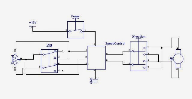
I simplified the wiring even more and ended up with this:
powerfeedtrace.jpg


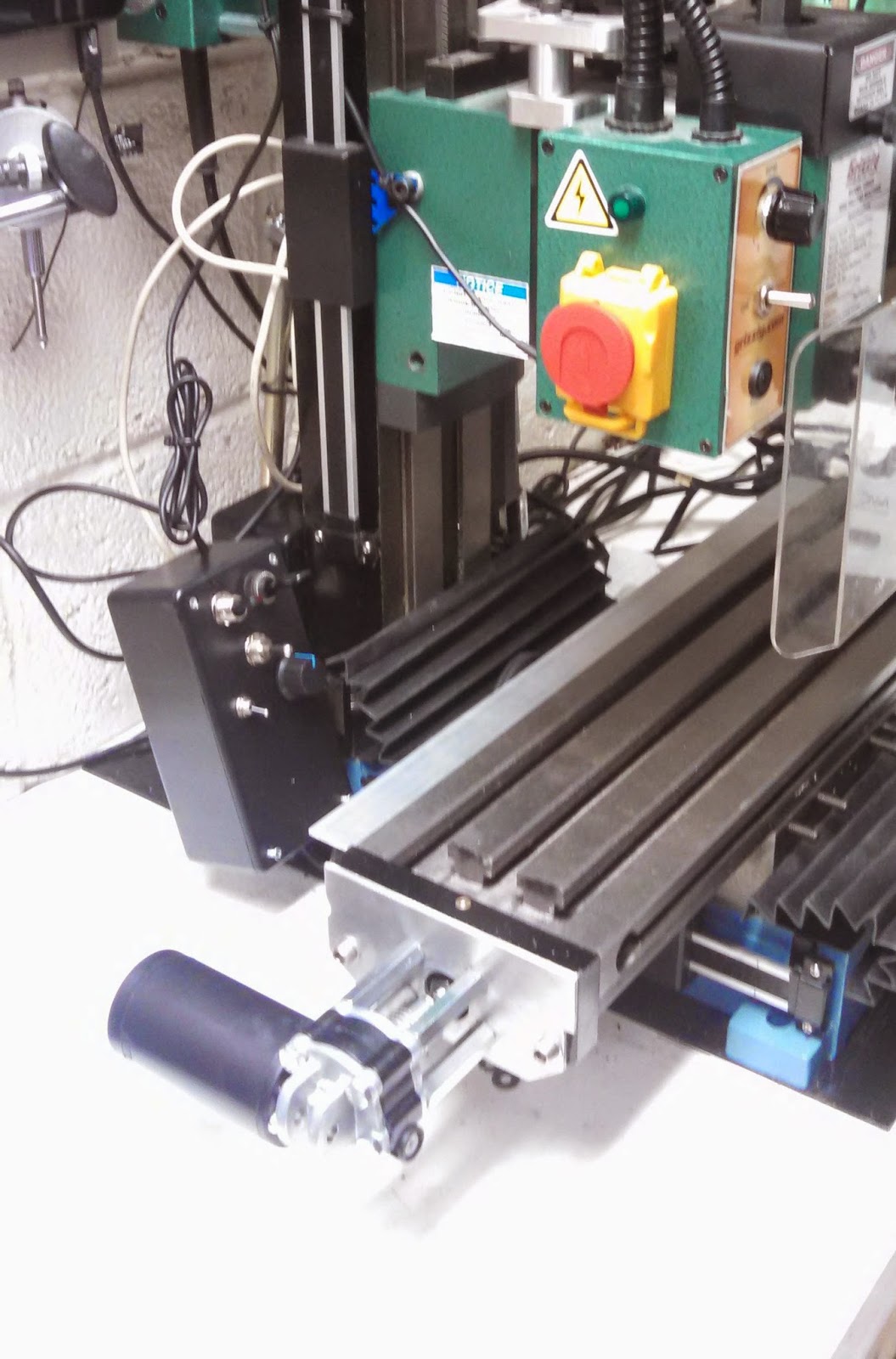
It works very well and I'm quite pleased. All the wiring was packaged up into a Radio Shack project box and fixed to the left side of the mill. The extra switch in the top right corner of the box controls my LED spindle light.

powerfeedcontrol.jpg


The power feed works quite well, though the motor will get a little hot after extended runs. The beta version of Touch DRO (Android DRO) I'm currently running will give you the feed rate for the selected axis, so with the power feed I can set my feed rate very exactly.

I'm happy.
 
That looks great ! I have noticed the motor warms up a little but I dont think its too much. It never gets to the point where I cant keep my hand on it.
Pete
 
That looks great ! I have noticed the motor warms up a little but I dont think its too much. It never gets to the point where I cant keep my hand on it.
Pete
More specifically, the end of motor gets hot, right where the shaft bearing is. I may pull it apart and see if there's enough lub there.
 
More specifically, the end of motor gets hot, right where the shaft bearing is. I may pull it apart and see if there's enough lub there.

Hi Zoltan,

I think I've mentioned this before...
These motors are a permanent magnet type (Permag). They don't have any field windings, all the heat is generated in the armature ! The only way that the heat can escape is via the bearings at each end. Since the tail bearing is a long PB sleeve the heat is conducted through that to the motor body. There is a short PB bearing at the other end and a small ball at the worm end of the shaft to take the end thrust. This is the reason why these motors don't like to be run backwards.

Whilst you can strip the motor down and add lubrication you shouldn't need to. The PB bearing is lubrication impregnated.

HTH.
Why could I help the motor run cooler then? Maybe throw a heatsink on the bottom?

Why would the motor not like being rung backwards? From what you've written I don't really see why that would be the case. Also, this is an actuator for a car's power seat, and in that application the motor would be run about equally in both directions, so why use a motor which prefers to be run in one direction only?
 
For what it is worth, I put a simple X axis power feed on my little Seig X1 Mill. the motor is an old Ford windscreen wiper and is coupled to the shaft with a chain drive. I built a simple speed control using a pulse controller ex Hong Kong. I also have found my work has a much better finish.

Your set up is much more sophisticated and I think one day I'll rebuild mine. Mean time I'm building a set up to power the Z axis using a 24 volt stepping motor - I' get tired of winding the darn Z axis handle.
C:\Users\David\Pictures\Uploads


Assembled Unit.jpg
 
Why could I help the motor run cooler then? Maybe throw a heatsink on the bottom?

this is an actuator for a car's power seat, and in that application the motor would be run about equally in both directions

Whilst my comments about direction were intended with respect to windscreen wiper motors it should be obvious that it doesn't apply to a motor intended to run in either direction.

As far as heat sinking is concerned the motor body is the heatsink and maybe a fan would help dissipate some of the heat.

It hadn't occured to me to look in the scrapyard for car seat motors ! I'll have to look next time I go there. Thanks for the heads up on those.
 
Zoltan:

The motor is getting hot because it was never designed for continuous operation. Think about, while it's the actuator for a car seat and designed to run in both directions, it only does that in short bursts and then, unless you're a little kid, it won't be used again for a long time. You need to start with a motor that is designed to run for long periods of time, or what is called continuous duty. If you want to stick to salvaged car parts, a windshield wiper motor or a heater blower motor would be a place to start. Both of those motors have to run continuously for extended periods of time. I realize that neither of those motors would be a easy replacement for your actuator motor, but if you want continuous cool operation you need a continuous duty motor.

That or just accecpt that your motor is going to run hot, and that the motor will not last as long as it normally would. Just be sure to buy some spares so that when the motor burns out at O Dark Thirty, and you're half way through that ever so complicated part, you can swap in a spare and keep on going.

Don
 

Hi Zoltan,

Thanks for that link. At least I now know the sort of thing I would be looking for. Whilst I may pay the man at the scrapyard some money, for me the satisfaction of turning junk into something useful at minimal cost is irresistible.

You have made a very nice job of yours. I looked at and saw from the video that it works very well ! Dare I ask if you have seen mine ?

http://www.homemodelenginemachinist.com/f28/my-table-traverse-chinese-mill-23130/

Actually this is the MK1. I'm in the process of designing MK2. Having discovered a couple of niggles and that I can't get the driving gear off the motor gearbox shaft without risking damaging the worm wheel.
 
Last edited by a moderator:
David
I have fitted a stepper motor to the z axis of my X1 mill and it works very well to date and i,m just in the process of doing the same to the X asis, I've just been waiting to finish my current project of the bottle engine, mine uses an arduino controler with an electronic clutch, it disengages the motor from the handle, the handle turns normaly until the motor engages, there's a vid of it working some where here.
 
You have made a very nice job of yours. I looked at and saw from the video that it works very well ! Dare I ask if you have seen mine?
I have indeed and think you did a great job. It's a lot nicer than I could have ever managed.
 

Latest posts

Back
Top