You are using an out of date browser. It may not display this or other websites correctly.
You should upgrade or use an alternative browser.
You should upgrade or use an alternative browser.
Wot can it be?
- Thread starter tel
- Start date

Help Support Home Model Engine Machinist Forum:
This site may earn a commission from merchant affiliate
links, including eBay, Amazon, and others.
- Joined
- Dec 28, 2008
- Messages
- 1,731
- Reaction score
- 9
Good job Tel. I see your moving right along at a good pace.
Today I started back up on mine, after being side tracked with my chuck mounting project and major clean up.
I'm about to start drilling holes in the column. after taking a look at the air passages I got stuck on the 'BB section' drawing in the upper right corner on page 249.
The plugged passage runs all the way through. This doesn't make any sense to me, thinking the engine couldn't possibly run with the upper intake and exhaust ports inter connected.
I was planning on tapping the passages 3-48 for set screw plugs since the 5/64" drilled passages are close to the correct size for tapping. I normally plug with removable set screws. This allows me to go back and make sure the passages are clear, and will also allow me to drill through (BB section) if necessary.
If this isn't a mistake, then is this needed because of the 90 degree offset of the crank throw? ???
-MB
tel
Well-Known Member
- Joined
- Feb 8, 2008
- Messages
- 3,293
- Reaction score
- 45
Nah MB - that BB section is definitely a mistake, the AA section shows how it should be correctly. In the event, I had no suitable 5/64" drill and went to 2mm, tapped the openings 6BA and put in tight screws that were then cut off and filed flush. I like your idea of removable screws - that could save a lot of problems.
Drilling the passages was pretty straight forward. The only concern I had was with that compound angled lubrication hole. In the end I scribed a light line in the correct position on one face and set that vertical in the vise, then slewed the head of the X2 over 20° - with the vise jaws parallel to the Y axis. Ran in with a 1.2mm drill, then opened out with a 1.4mm - about as big as I dared to go. Seems to have worked out OK - oil squirted in the end comes out the trunnion hole and no where else.
The only other change, so far, is that I thought that space was a bit tight for opening out the trunnion hole for a bush. so I used a bit of K&S 1/4" brass tube to bush the existing hole - means that I'll have to hold the trunnions down to 5.6mm, but that shouldn't make a lot of difference.
It's an interesting build.
zeeprogrammer
Well-Known Member
- Joined
- Mar 14, 2009
- Messages
- 3,362
- Reaction score
- 13
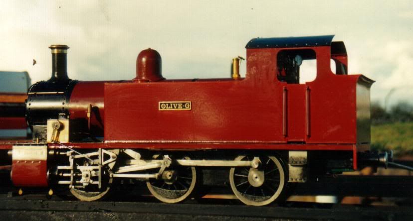
tel said:There's probably 15 finished engines here and 1 loco. Time and weather permitting I might try and dig a few out over the weekend and put up a bit of a gallery for ya.
stickpoke
I'd like to see them...especially the loco.

$39.99
$49.99
Sunnytech Low Temperature Stirling Engine Motor Steam Heat Education Model Toy Kit For mechanical skills (LT001)
stirlingtechonline

$188.98
TM NEXDYNAMI RE41157 Water Pump Compatible With/Replacement For/John Deere 6200 7400 6300 6600 6500 6400 7220 7600 7200 RE41157
VIVID MARKET CORPORATION

$99.99
AHS Outdoor Wood Boiler Yearly Maintenance Kit with Water Treatment - ProTech 300 & Test Kit
Alternative Heating & Supplies

$40.02
$49.99
Becker CAD 12 3D - professional CAD software for 2D + 3D design and modelling - for 3 PCs - 100% compatible with AutoCAD
momox Shop

$154.75 ($1.38 / oz)
Replacement Combustion Chamber Kit, Burnham V8 and V8H, 1-6 Sec, 108136-01, 1129
Plumbing Planet

$109.99
AmTech300 - Boiler Treatment Professional Strength (Rust Inhibitor For Outdoor Wood Boilers)
Alternative Heating & Supplies

$94.99
$109.99
AHS Woodmaster 4400 Maintenance Kit for Outdoor Wood Boiler Treatment
Alternative Heating & Supplies

$426.53
DM14 Engine Build Kit, Metal Engine Build Model Great Metal Material for Engineer for Factory
Easoger Official

$29.95
Competition Engine Building: Advanced Engine Design and Assembly Techniques (Pro Series)
Amazon.com Services LLC

$649.00
$699.00
FoxAlien Masuter Pro CNC Router Machine, Upgraded 3-Axis Engraving All-Metal Milling Machine for Wood Acrylic MDF Nylon Carving Cutting
FoxAlien Official
vlmarshall
Well-Known Member
- Joined
- Dec 28, 2008
- Messages
- 1,138
- Reaction score
- 1
ooooh! oooh! We wanna see the loco! ;D
Nice loco. Looks like the "Simplex" from Model engineer,1967 or so, I think. Is it?
I have the whole build article on it and have been studying it but the cost of copper tube for the boiler has me just dreaming about it. 4 in well over $100 US.
I've even been thinking of ways to fab up the cast parts from bar stock. Oh well dreams are nice. :big: :big: I'm not good enough to tackle something like this ----YET.
Ron
zeeprogrammer
Well-Known Member
- Joined
- Mar 14, 2009
- Messages
- 3,362
- Reaction score
- 13
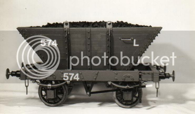
Nice looking loco and coal car tel. Thanks for posting them.
I'm almost sorry I asked! :big:
I am definitely building a loco...someday.
I'm almost sorry I asked! :big:
I am definitely building a loco...someday.
tel
Well-Known Member
- Joined
- Feb 8, 2008
- Messages
- 3,293
- Reaction score
- 45
There's a bit of a story goes with that coal wagon. On the originals, the planking is held to the hopper frames with plain round head bolts. Now, being keen to do the right thing I made up a little hand jig and proceeded to make some 300 7BA bolts out of 3/32" rivets - usually doing a few while watching TV - almost an automatic process - until Mrs Tel remarked on the tiny metal shavings that were mysteriously appearing in the lounge room. Any'ow, to cut a long story short, I finished making all of them eventually, and installed them true to prototype, with the heads on the inside of the hopper, then proceeded to fill the dang thing with fine coal, and the heads have never been seen since!
max corrigan
Well-Known Member
- Joined
- Aug 24, 2008
- Messages
- 156
- Reaction score
- 4
Tel good work! dunno if i missed it, but did you fabricate the crankshaft, or do it nail biting way out of one lump
Regards Max
Regards Max
tel
Well-Known Member
- Joined
- Feb 8, 2008
- Messages
- 3,293
- Reaction score
- 45
Thanks blokes.
Max, the crankshaft was fabricated, as per Elmer's instructions (well, almost as per). It was one of the easier crankshafts to do, with that big 'flywheel' section in the middle.
Nick, the 'pivoty' bit is actually fixed in position, it is really only there to carry the tensioning screws that bear on the balls/springs that hold the cylinders up against the port faces. There are a number of ways of doing this, but that is the Gospel according to Elmer, so I went with it.
Looks pretty grubby there, covered in oily fingerprints - it was straight from a running in session on the lathe
tel
Well-Known Member
- Joined
- Feb 8, 2008
- Messages
- 3,293
- Reaction score
- 45
Similar threads
- Replies
- 1
- Views
- 1K
- Replies
- 0
- Views
- 669


![MeshMagic 3D Free 3D Modeling Software [Download]](https://m.media-amazon.com/images/I/B1U+p8ewjGS._SL500_.png)


