Whittle Aero V8 WIP

Home Model Engine Machinist Forum

Help Support Home Model Engine Machinist Forum:

This site may earn a commission from merchant affiliate links, including eBay, Amazon, and others.
Yeah Vernon,
You don't need a drawing.... the mental picture alone says it all :big:

I'm going to have to take my time....2 chips at a time......and.....hopefully when I put the pin gage in each side and measure.....They are within a couple of thou of each other.

Fingers crossed

Tony

PS George B is an artist....see if he'll draw us a cartoon
 
Good luck! I'll be thinking about ya tomorrow... while I'm drilling .014" holes in tool steel at work. ;D
 
Thanks Vernon....and it sounds like you'll need a little luck too!

To the both of us Thm:

Tony
 
Condolences on the loss , but a hearty hand shake to the intestinal fortitude!.....Keep swinging Tony!

Have you considered line boring it?..at least to reamer size?....just a thought.

Dave

 
steamer,
Thank you very much. I was thinking about a tool for line boring the crankshaft bearings. The plans call for a 6mm shaft cut down a bit in the center of the length and a tool bit and set screw. Man that's small.
So I was thinking of a 6mm shaft and cut a "D" reamer in the middle. I'm thinking if doesn't work tonight then a similar tool might work.

Tony
 
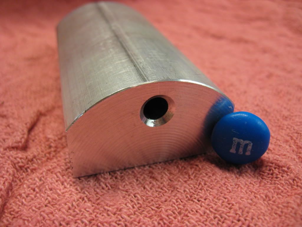
Well tonight I will join the M&M club.No sense being left out from the IN club.

IMG_0796.jpg


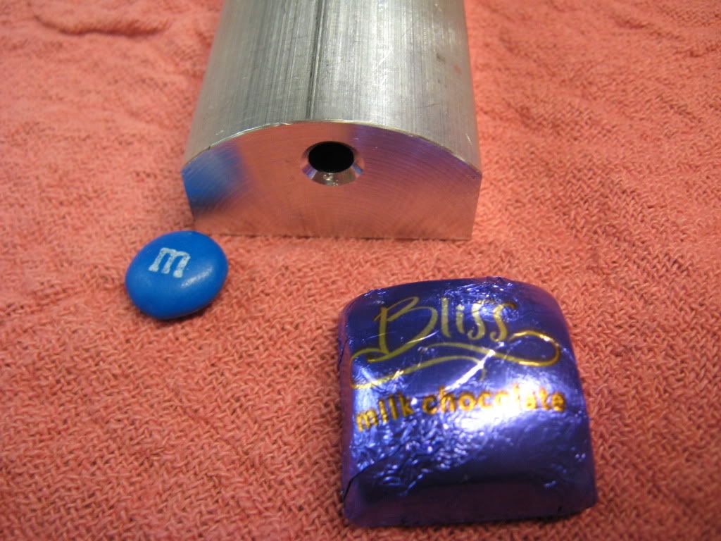
I'll see that M&M and raise you a Bliss

IMG_0799.jpg


Anybody detect the oh shirt in my typing

Still off .010 left and right front to back and top to bottom on the camshaft bore. Somebody tell me I'm Crazy, that's OK how close do you want to get it???

+/- .002 would be nice and I think that's what it needs to be.

Tomorrow I will try to massage it in .005 off here and there ....maybe. I think I need to cut the upper .010 larger then drill the cam hole then bring it home by cutting the outside to fit.

Time for some thought and .......

Tony

 
This might seem a rather flip remark, then again, maybe not. Maybe just an odd way of thinking...

How about drilling the holes, then machine around that as the datum?

Like I said, just an odd way of looking at the problem. Disregard as you see fit.
 
ksouers,
Thanks for your input!
You maybe right! I thought of that a while ago but....looking for the easy way out! But. There is no easy way! I'm thinking that it's going to be a little of this and a little of that kind of thing. I need to "massage" it into spec.

Tony
 
Glad to help.

That may not be your solution, but maybe thinking about the problem differently will help you find it.


Good luck. I'll be watching ;)
 
ksouers,
I need support now....This thing is kicking my a....ss now ....but...... I will prevail....Nice to know I've got Friend's!

Tony
 
How about leaving the block oversize and squaring to whatever hole you get? Maybe not true machinist form, but if you don't tell anyone, I won't. If you go this route PM me and I'll make like this post never existed. ;D
 
dieselpilot,
At this point I don't care how I get there. I know how I can reach it...I think. You are right drill the hole then fit the block around it.

Thanks Man Or should I say Mate?

Tony
 
I once had a similar problem. I drilled halfway through with a small drill then I step drilled it a couple sizes. Feeding slow If I remember right then reaming it last. You are doing a nice job though:eek:)
 
Tony,
Sorry that the new methods did not prove successful.

I think that Diesel's method may be the best approach. I worked up a procedure to do it that way, but by now you probably have something underway.

I pulled mine out and measured it using a surface plate and indicator. Mine measures just under 0.005 total difference in position, or about 0.0025 out of position. I can't see that hurting anything. As long as the hole is straight so the cam runs freely. Just have to be careful about clearance with the cam followers and guides.

I was using a gauge pin to test with and it was not quite long enough to stick out both ends at the same time. So I pulled out the length of 7/32 drill rod I have reserved for this project. I discovered that it is not as straight as I would like. Found a fairly straight section and cut that out. Measurments were the same as the gauge pin. I probably will order a new length of name brand of drill rod when the time comes. Probably won't make any difference. I would guess that the distortion from hardening will be greater than the bow in the rod I have.

Gail in NM

 
Just spitballing here, Tony, but I wonder if you could use some kind of stepped reamer held between centers as a kind of align boring bar. You would have to make it, I think. Four flutes should do.

It would depend on your lathe being long enough, and setting up the crankcase half on the cross slide. Your head and tail will need to be dialed in dead on.

The reamer would need a long plain end on the end that goes in the tail stock center. Long enough to go clear through the crankcase before the reaming edges engage the piece. Then flutes on the rest of it, a little longer than the crankcase. Picture a counter bore with a very long pilot, but you wouldn't want the pilot to touch the sides of the bore.
I think I wouldn't harden it, to rule out warping the tool.

A true align boring job will get this straight, too. That's a pretty small bore though, so would need a small bar, of course, and very light cuts.

Or, you could forget that stuff, be sensible, and make the piece around the cam bore. I don't think it is a cheap way out. Doing it wrong and leaving it that way is the cheap way out. Working to a datum, where ever it is, seems to make sense. That's what we do when we indicate off a bore on a piece in a four jaw chuck, or on an RT, after all!

Dean
 
The bottom line is that the cam bore has to be in line and straight. I don't believe that how it gets there makes any difference, there isn't any cheating it.

The camshaft bore, out of necessity IS your datum on this part. Being out of line will cause grief the rest of the way through the build. These small engines are, in my opinion, much more finicky in location tolerances than even their full-size counterparts which, BTW are commonly fixtured from the crank and cam bores for machining.

I would get the hole in straight and on size, making sure there's enough material to bring the block to size and located to the hole. When I was working as a mold-maker, this became common practice on a lot of parts we made, the critical holes were put in first and the rest located from the hole.

I am not saying that it can't be done, but there's more than one way to skin a cat.

Best of luck to you with whatever method you end up using; short of having fancy gun drills, jig borers, or wire EDMs, sometimes luck is what we use.

Kevin


Here's a boring bar I made to cut a 0.354-10 LH ACME ID thread.

The body is .1875 and the screw is 4-40.

It can be done......but tedious oH so very tedious

P1010117.jpg


P1010123.jpg


Baring a boring operation, I think the "make the hole and build the part around it" approach is a good bet....PROVIDED the hole is straight....drills can make curved holes sometimes.....beware!
A toolmakers reamer ( or a D bit) should be used to straighten the hole out and bring to size.....but I'd try boring it first...at least to reamer size
Dave
 
Wow Tony, you're doing a grand job here. I really need to go through this thread again from the start!

Like the M&M touch!

Nick
 
3 hrs of set up double check.....triple check.....new reamer......and the cam hole is +/- .002 all around front to back top to bottom left to right. I brought to size then drilled. This time I made sure of a couple of things which I didn't the last time. Machined surface against fixed vise jaw and I used a piece of 1/2" precision tool steel rod in the collet to square the piece up side to side.

th_wav

Tony
 

Latest posts

Back
Top