Bruce, I hear you. It's not fun being sick. Hope you feel better soon.---BrianBrian, mine's hit a snag in the form of a worn (or damaged) MT2 taper on my mill and awaiting a new one to come from agent. Then I have to fit it and tram the mill. Plus I have been laid up with a bit of a head cold which has not been condusive to workshopping. Hopefully some movement soon.
Cheers
Bruce
You are using an out of date browser. It may not display this or other websites correctly.
You should upgrade or use an alternative browser.
You should upgrade or use an alternative browser.
Vertical I.C. Rupnow Engine
- Thread starter Brian Rupnow
- Start date

Help Support Home Model Engine Machinist Forum:
This site may earn a commission from merchant affiliate
links, including eBay, Amazon, and others.
Cogsy
Well-Known Member
I'm still making some progress Brian. I'll post a proper update in a day or two. Like you, I'm eagerly waiting to hear Herbie has his running as well.
- Joined
- Mar 1, 2010
- Messages
- 866
- Reaction score
- 82
Brian, mine's hit a snag in the form of a worn (or damaged) MT2 taper on my mill and awaiting a new one to come from agent. Then I have to fit it and tram the mill. Plus I have been laid up with a bit of a head cold which has not been condusive to workshopping. Hopefully some movement soon.
Cheers
Bruce
Bruce
Give David T a call. I know he's got MT reamers. If you pull out the quill I'm sure he could help you get it reamed on his gear.
Pete
bruedney
Well-Known Member
Thanks Pete
So do I but the spindle is hardened and it was going to cost twice the amount of a new one to have it ground
Cheers
Bruce
So do I but the spindle is hardened and it was going to cost twice the amount of a new one to have it ground
Cheers
Bruce
Cogsy
Well-Known Member
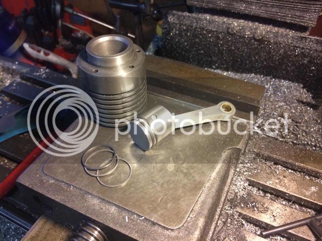
Thanks to a very generous fellow member, I got a piece of absolutely beautiful-to-machine cast iron and managed to carve a cylinder out of it. It was going very well and I'd virtually finished it when I managed to dig a tool in and eject it from the chuck :wall:. It survived but suffered some cosmetic damage and I had to lose the top, very thin cooling fin. In the photo the fins look burred but it's actually just loose swarf in there.
Although I intended to follow the plans fairly tightly with this build I've deviated somewhat and built an aluminium piston with cast iron rings instead of an o-ring. I made a few extra in case I needed them and I've left the extras un-split and not heat treated for now.

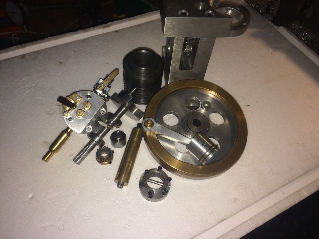
Here is a family pic of where I'm at right now. I still need to make a few fasteners and gaskets as well as sort out an ignition of some sort and something to mount it on, and the fuel tank and bracket as well. As I'm prone to getting sidetracked easily once an engine is running, I plan on getting this one pretty well finished before I attempt to start it.

So still lots to do and it'll be a while yet, but I'm still enjoying the build. Time will be getting tighter for me soon though.
Although I intended to follow the plans fairly tightly with this build I've deviated somewhat and built an aluminium piston with cast iron rings instead of an o-ring. I made a few extra in case I needed them and I've left the extras un-split and not heat treated for now.

Here is a family pic of where I'm at right now. I still need to make a few fasteners and gaskets as well as sort out an ignition of some sort and something to mount it on, and the fuel tank and bracket as well. As I'm prone to getting sidetracked easily once an engine is running, I plan on getting this one pretty well finished before I attempt to start it.

So still lots to do and it'll be a while yet, but I'm still enjoying the build. Time will be getting tighter for me soon though.
Good job Cogsy.--You're keeping the build ALIVE!!!---Brian
![DreamPlan Home Design and Landscaping Software Free for Windows [PC Download]](https://m.media-amazon.com/images/I/51kvZH2dVLL._SL500_.jpg)
$0.00
DreamPlan Home Design and Landscaping Software Free for Windows [PC Download]
Amazon.com Services LLC

$89.99
Outdoor Wood Boiler Water Treatment Rust Inhibitor- AmTech 300 & Test Kit
Alternative Heating & Supplies

$99.99
AHS Outdoor Wood Boiler Yearly Maintenance Kit with Water Treatment - ProTech 300 & Test Kit
Alternative Heating & Supplies

$519.19
$699.00
FoxAlien Masuter Pro CNC Router Machine, Upgraded 3-Axis Engraving All-Metal Milling Machine for Wood Acrylic MDF Nylon Carving Cutting
FoxAlien Official

$24.99
$34.99
Bowl Sander Tool Kit w/Dual Bearing Head & Hardwood Handle | 42PC Wood Sander Set | 2" Hook & Loop Sanding Disc Sandpaper Assortment | 1/4" Mandrel Bowl Sander for Woodturning | Wood Lathe Tools
Peachtree Woodworking Supply Inc

$45.99
Sunnytech Mini Hot Air Stirling Engine Motor Model Educational Toy Kits Electricity HA001
stirlingtechonline

$24.99
$27.99
HOZLY 5PCS/Lot ISO30 Tool Holder Clamp Flame Proof Rubber Claw CNC Machines Automatic Tool Changer
HOZLY

$94.99
$109.99
AHS Woodmaster 4400 Maintenance Kit for Outdoor Wood Boiler Treatment
Alternative Heating & Supplies

$12.56
$39.95
Complete Plans for Building Horse Barns Big and Small(3rd Edition)
ThriftBooks-Atlanta

$40.02
$49.99
Becker CAD 12 3D - professional CAD software for 2D + 3D design and modelling - for 3 PCs - 100% compatible with AutoCAD
momox Shop

$39.99
$49.99
Sunnytech Low Temperature Stirling Engine Motor Steam Heat Education Model Toy Kit For mechanical skills (LT001)
stirlingtechonline
Cogsy
Well-Known Member
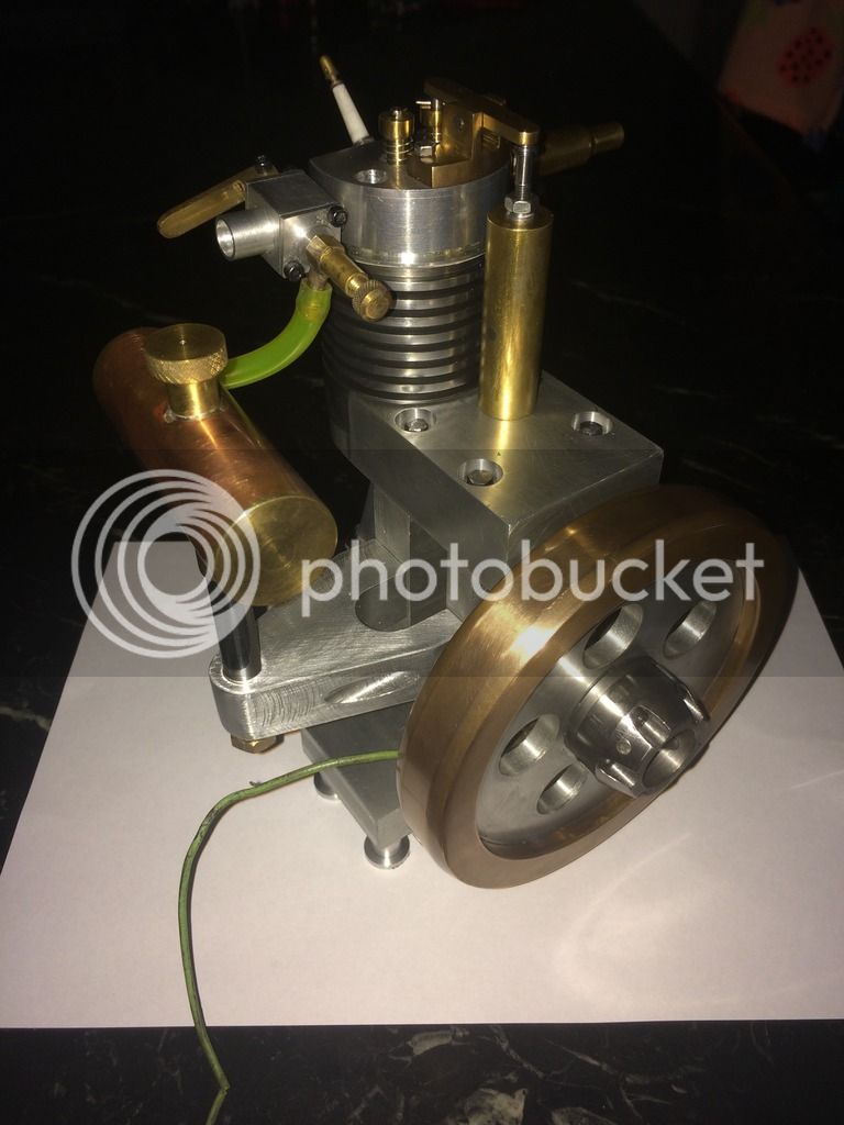
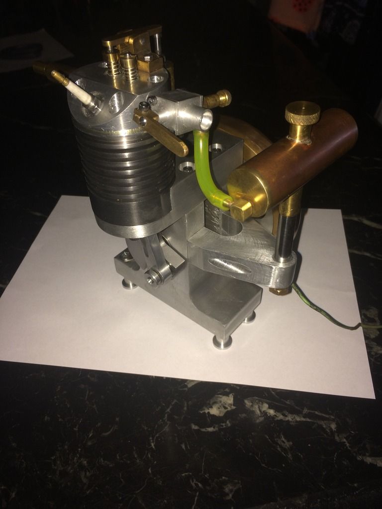
Attempted a trial assembly today just to see how things fitted together. All went well with only a couple of minor tweaks needed. Now it's pull it all down and get ready for proper fit and finish, then bash up some sort of wooden base and finally it will be time to try starting it up. With luck I might have a runner some time this week.
I found an old distributor in the shed (from a Cleveland V8 ) and I've repurposed the points from that. For the coil I dug one up that is marked with a warning about only being suitable for electronic ignitions. I don't know what it will do to a set of point but I guess I'll find out!


I found an old distributor in the shed (from a Cleveland V8 ) and I've repurposed the points from that. For the coil I dug one up that is marked with a warning about only being suitable for electronic ignitions. I don't know what it will do to a set of point but I guess I'll find out!


Very nice, Cogsy.--I will have my fingers crossed for you.---Brian
Cogsy
Well-Known Member
I reworked the few things I had to and got it to the point where I could attempt a start. I videoed my attempt with the idea of showing how I fiddle with settings while spinning the engine with an electric drill, til it gets to the point where it fires regularly and slowly beds in the valves (and the rings somewhat) and eventually runs. I didn't expect it to start firing almost straight away and to start running so soon. This has been the easiest first start by far of any of the engines I've built.
The video proof:
[ame]https://www.youtube.com/watch?v=U4rsXymF1NM&feature=youtu.be[/ame]
However, as I thought there was a distinct possibility of having to re-lap the valves before getting the engine to run, I hadn't secured the valve retaining pins at all. I got a warning when the exhaust one nearly worked it's way out, but I didn't heed it and I ended up dropping the intake valve. The valve is bent (only a small amount but totally unusable) and I noticed after reviewing the video that the sudden stop has moved the crank disc on the crankshaft - there must have been quite a bit of force involved. It's not a difficult fix and I'm happy the crankshaft absorbed some of the shock rather than punching a nasty hole in the piston or something equally as bad.
Here's the 'blow-up' video.
[ame]https://www.youtube.com/watch?v=_A_jdkNxEL4&feature=youtu.be[/ame]
I might have to take a bit of time off before I get the repairs done, but I officially HAD a runner, and unless I'm mistaken, the first Rupnow Vertical to run with cast iron piston rings. As a side note, the table I used as a bench is extremely flimsy so the vibration seen in the video is because of that. I think the engine might be quite well balanced. I'll know more once I get a base made and try it without having it clamped down.
Finally, a big thanks to all that helped out with advice, etc. on the build, to my generous cast iron supplier and of course to Brian for his fantastic (and free!) plans.
Congrats Al, Great to see it running, shame about the valve keeper pin.
I use 2mm E clips on the valves that are recessed in the spring keeper.
Cheers
Andrew
I use 2mm E clips on the valves that are recessed in the spring keeper.
Cheers
Andrew
DavidLloyd2
Well-Known Member
- Joined
- Jul 16, 2016
- Messages
- 84
- Reaction score
- 111
Congrats Cogsy on a runner Looks and Sounds good.
That valve keeper pin Don't feel to bad Been there Done That,
Cheers
DavidLloyd
That valve keeper pin Don't feel to bad Been there Done That,
Cheers
DavidLloyd
Congratulations Cogsy--a great runner, the fourth in the world if I haven't lost count.--and yes, the first with real metal rings.---Brian
Matt,Good morning, I am after a set of these plans, but am unable to locate them, could somebody steer me in the wright direction.
Kind regards Matt
They are listed back in the thread, I can not upload the zip file as it is too large.
Zip file link can be found on page 17 post 167. You may like to read the hole thread as there is a lot of info and tips on how to build this engine.
Hope this helps.
Cheers
Andrew
Herbie--I haven't forgotten you. Did you get the new set of points yet?---Brian
Cogsy
Well-Known Member
I made two new valves, this time using Ghosty's method of retaining them with an e-clip which is recessed into the top of the valve keeper for extra safety. I didn't make new valve cages and simply spent about 2 minutes per valve lapping them in with toothpaste. When I reassembled it there was absolutely zero compression turning it over by hand, which worried me until I noticed I hadn't installed the spark plug. Once the plug was in compression was quite good.
The crank didn't take much effort to press apart and I was able to determine that the shaft had spun in the web about 45 degrees. Not wanting to make a new crankshaft or web, I simply ran a heavy, coarse diamond knurl on the end of the shaft and pressed it back together with a liberal amount of 635 Loctite.
Once the Loctite had cured I attempted a start and it fired straight up and ran immediately. All up I've got about 10 minutes of running on it so far, but as Brian experienced I cannot keep the flywheel grubscrews tight (I built version 1 of the flywheel with the smaller hub and grubscrews before it was redesigned). While it was apart I machined a small dimple in the shaft for one of the grubscrews to locate into, so the flywheel doesn't walk off the shaft, but it makes a lot of rattles and clonks as it runs. I'm thinking I'll have to make up a new tight fitting custom key with a very slight taper on it which locks the flywheel in place, as per George Britnells' suggestion.
I'll also have to hunt down some sort of cooling fan and mount it up. The engine is such a great runner that I'm sure I'll be wanting to run it for extended periods which wouldn't be a good idea without some cooling. Plus, with all the power the thing has, I will have to construct something for it to actually drive at some point. With the open design of the engine frame, I'm thinking about maybe building a power take off driven from the cam or crank gears rather than a putting a pulley outboard of the flywheel.
Here's a fairly poor pic of the new valve retaining clip. The engine looks grotty as it was still warm from it's last run when I took the photo and I'm making sure it's well lubed up while it runs in.

I know that I'm off and running on a new engine project, but I haven't forgotten my builders on this thread. What's up guys? There are still two engines being built that I haven't seen any updates on in a long time. Is there anything I can do to help?----Brian
If you could invent more free time that would be cool.
Life has been busy - a weekend at colonial Williamsburg, sick the next weekend and this past weekend gad to put in 16 hrs of unpaid overtime, two vehicles needed oil changes, one friend needed help removing a prop from his inboard, then has to straighten and put back in the right curvature in one blade. Amother friend needed the guides i made him for measuring tenons for post and beam construction modified. Another friend needed some help automating inventory pricing for hus business.
Life has been busy - a weekend at colonial Williamsburg, sick the next weekend and this past weekend gad to put in 16 hrs of unpaid overtime, two vehicles needed oil changes, one friend needed help removing a prop from his inboard, then has to straighten and put back in the right curvature in one blade. Amother friend needed the guides i made him for measuring tenons for post and beam construction modified. Another friend needed some help automating inventory pricing for hus business.
Similar threads
- Replies
- 0
- Views
- 719
- Replies
- 10
- Views
- 729
- Replies
- 2
- Views
- 2K


