V-TWIN---MAYBE V-4

Home Model Engine Machinist Forum

Help Support Home Model Engine Machinist Forum:

This site may earn a commission from merchant affiliate links, including eBay, Amazon, and others.
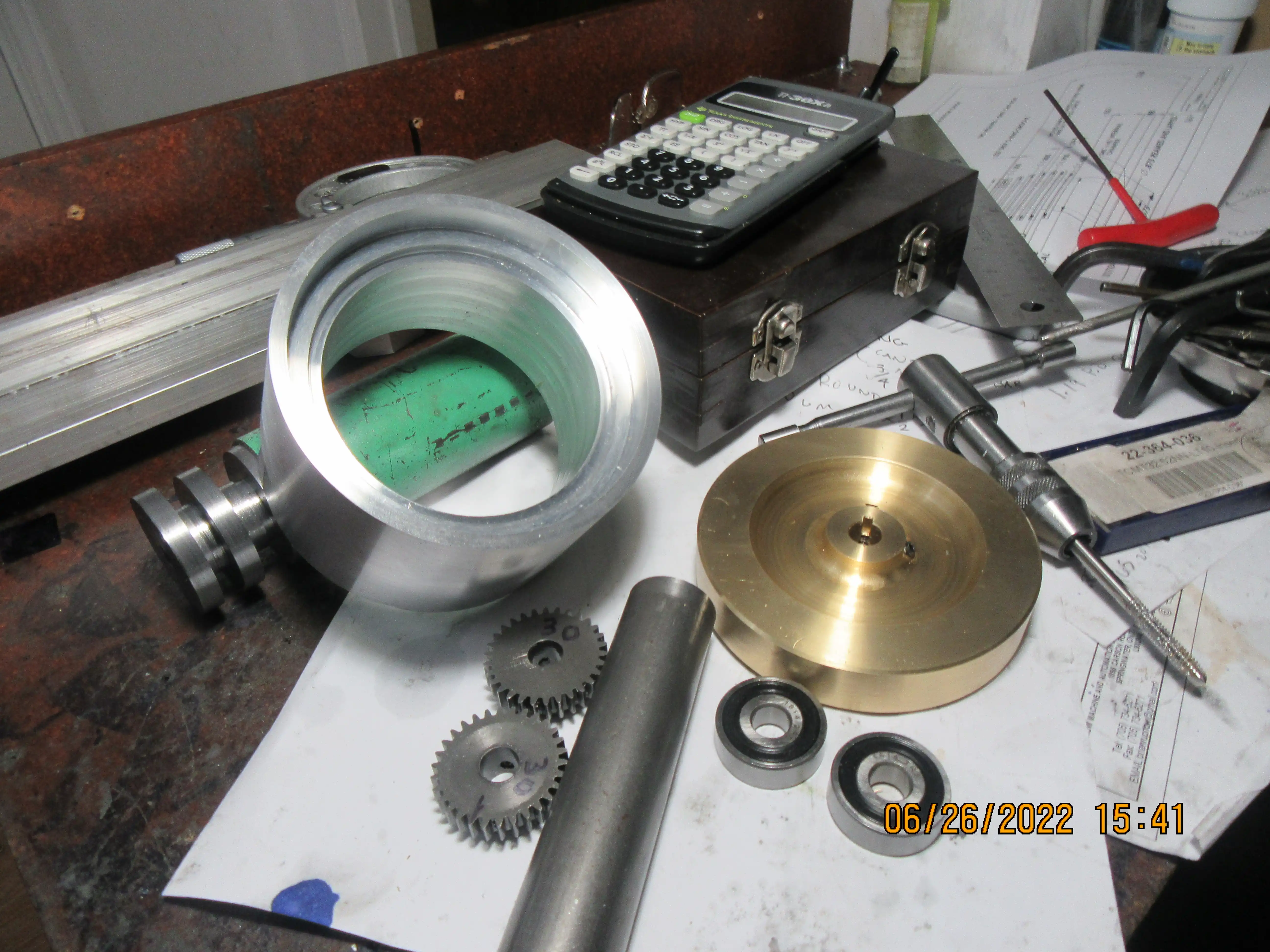
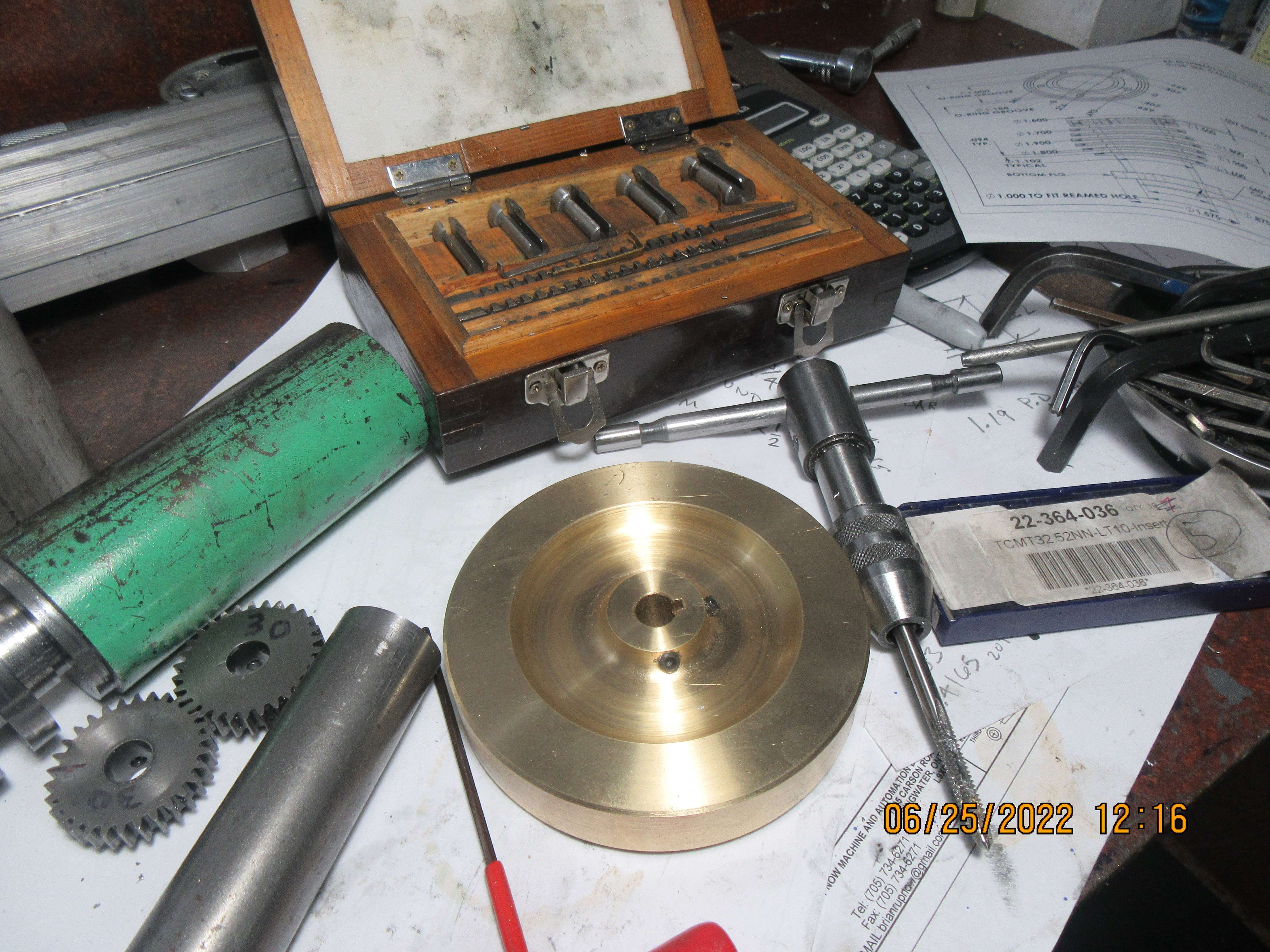
After thinking about it for a bit, I decided to go with a brass flywheel. I could have used mild steel (which I already had) but decided it was worth $25 just to avoid all the bandsawing and shaping involved in making the piece from a 1" mild steel plate. I do love those radiused inside corners.
oq34YN.jpg
 
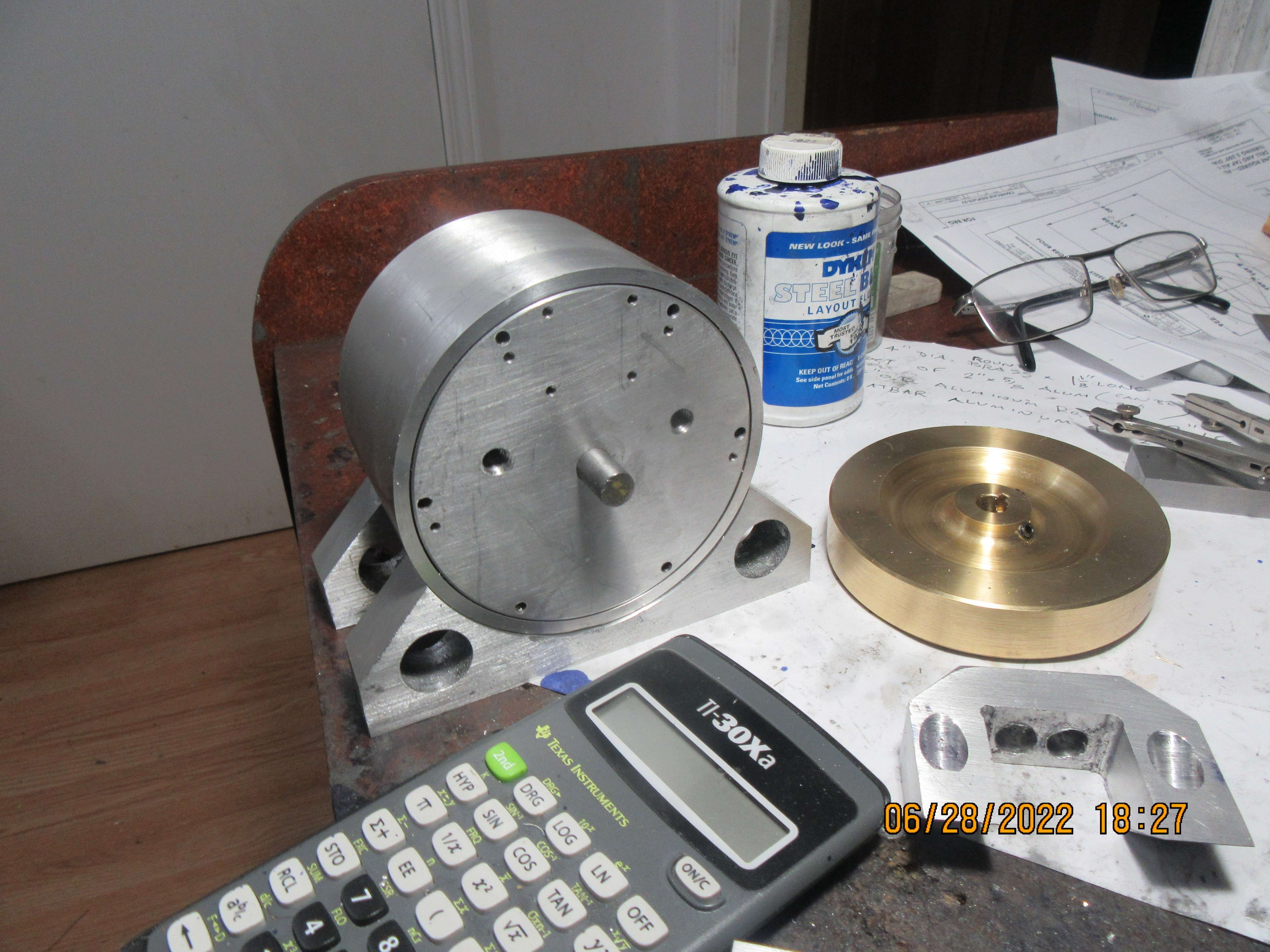
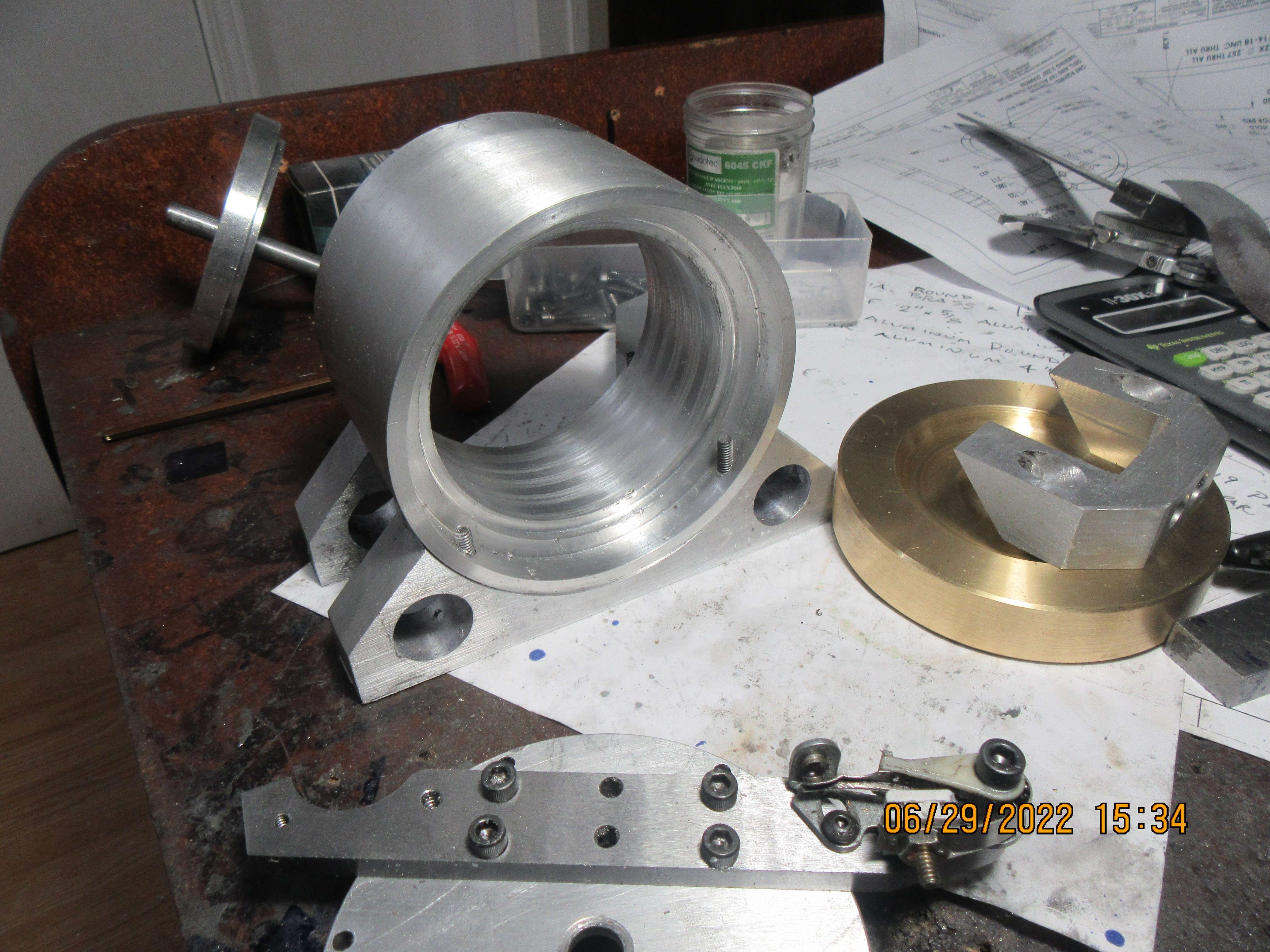
Today was crank-case day. I started with a piece of 4" diameter solid aluminum. My largest drill is one inch diameter, and the finished hole diameter is 3".--So, you know what I've been doing for a goodly part of the day---boring. and boring, and --boring. All of the inner features are finished now, so next thing will be milling the flats for the cylinders and camshaft supports to bolt to.
OT8OiQ.jpg
 
Gordon--You are absolutely right. A month ago I was so tired of machining things that I wanted to take the summer off and do other interesting things. Come to find out that at 75 years old, there just aren't that many other interesting things to do. I've read until my eyes are sore and I've used up all the good books that I wanted to read. Grandchildren are too grown up or live too far away to go and spend time at the beach. All my yard work is caught up, and I'm starting to drive my good wife crazy, looking for something to do. ---Brian
 
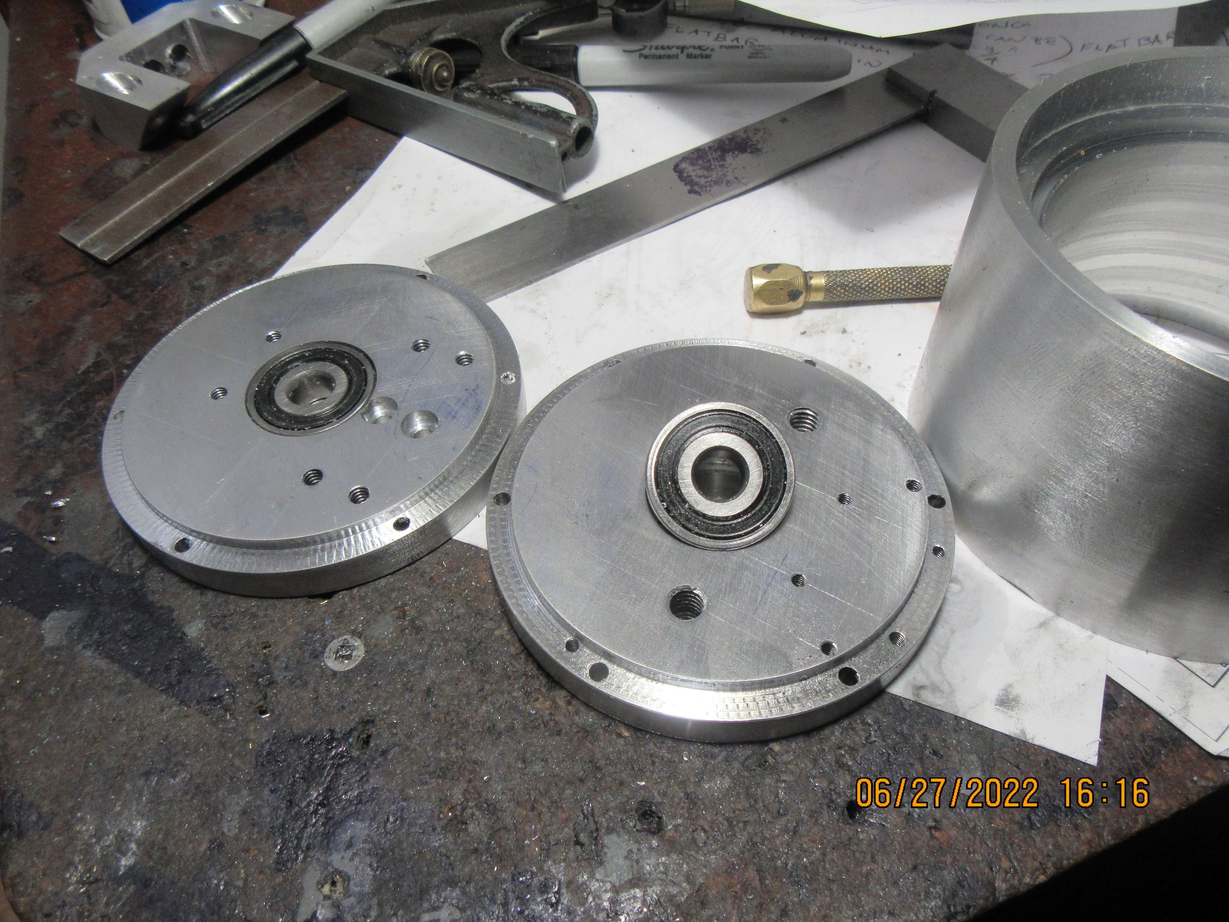
Today I managed to crank out a pair of crankcase endplates. The 3/8" sealed ball bearings fit into a recess bored on the inside of each end plate. Lots and lots of other small holes, some tapped, some not.
fWL141.jpg
 
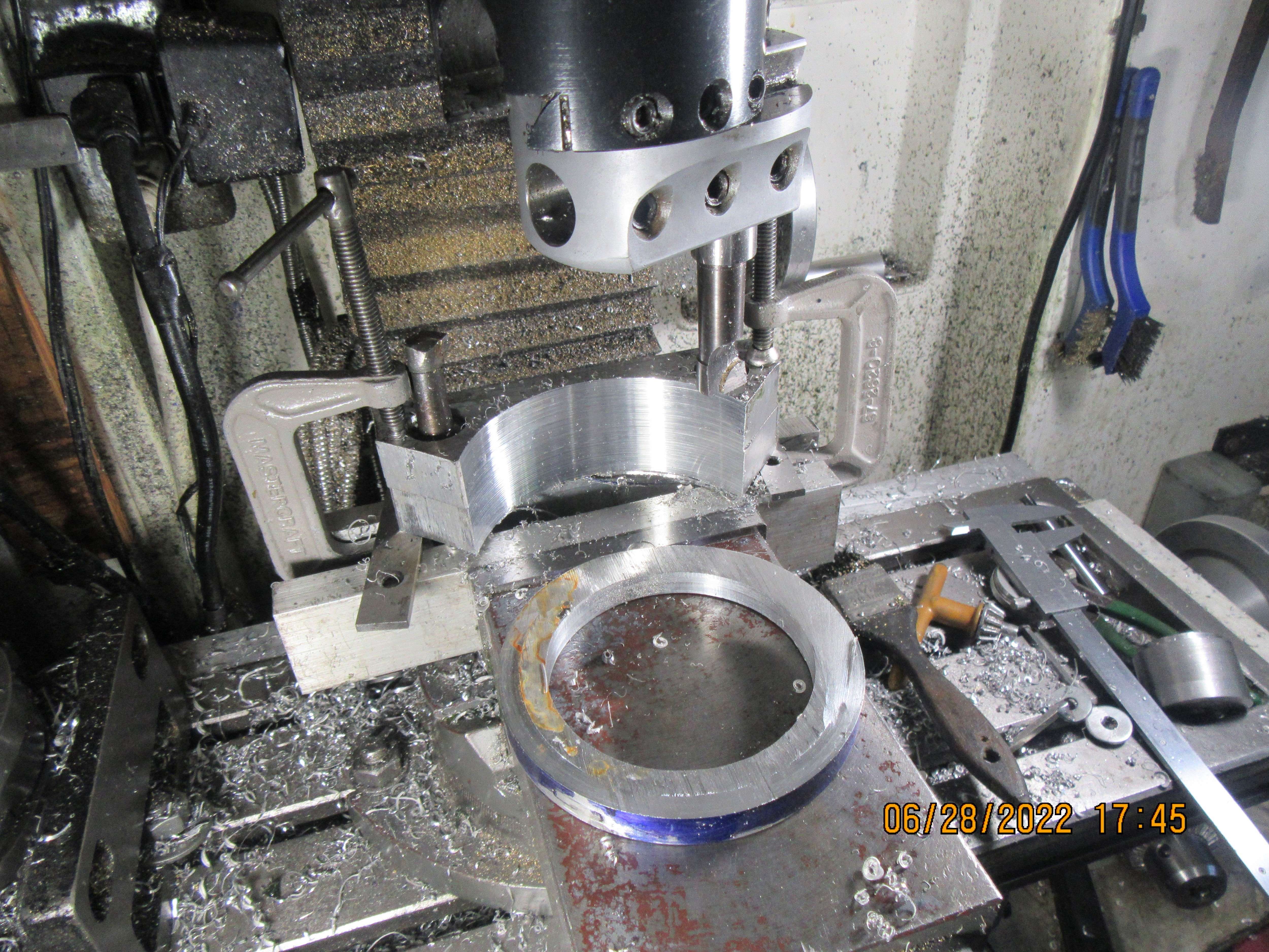
Sometimes when I am machining parts, I'm making it up as I go along. I should have turned the two inch radius in these engine support brackets with them mounted on my lathes faceplate. However, that would have involved drilling and tapping hold down holes in my parts or my faceplates, so it was machined on my mill. My boring head will just reach a 4" diameter cut, and I already had the 3/4" holes designed more for "pretty" than anything, but at the last minute I drilled them undersize and reamed them to 0.750". That let me gang the two plates together and push in some boring tools with 3/4" shanks. I hogged out most of the material with my bandsaw, so the job went quite well on the mill, even though it required a wacky set-up. As you can see in the pictures, they turned out quite "spiffy". I was away part of the day, attending a graduation ceremony for my oldest (18 years) granddaughter, who surprised us all with graduating from high-school as an "Ontario scholar"--which means with an 80 percent or greater average grade. Way to go Hannah!!!
wpsQas.jpg

NrAdIO.jpg
 
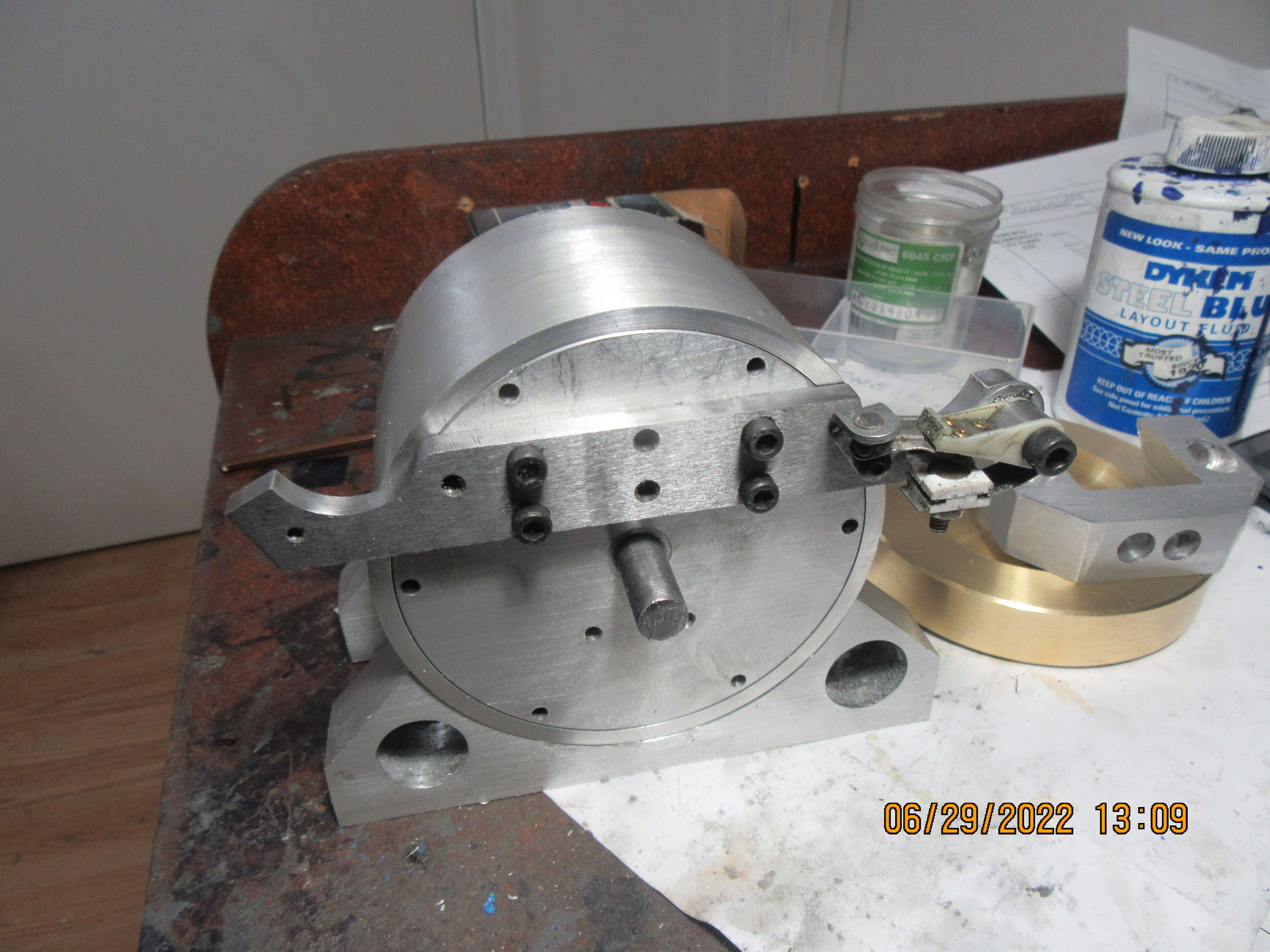
And now I have a place to mount my two sets of ignition points. I have one ratty old set of points that were damaged in the past. They work very well to just bolt in place and confirm that I have made the drawing correctly.
UlU1pi.jpg
 
And that's it for today!! The support feet are attached to the crank-case. I have to trim the length of the bolts, but that can be tomorrows job.
Gcp5PA.jpg
 
At this point in the game, just as I am about to machine the cylinders, I have changed the design of the cylinders and cylinder heads. My original cylinders and cylinder heads were exact copies of the cylinder and heads that I used on the 7/8" bore horizontal. These cylinders were tapered at the top, and the heads were 1.6" diameter. I have decided that due to the mass of the crank-case, the cylinders and heads had to appear larger. This didn't change anything internally---it's just that with the taper removed, the cylinders and heads "grow" to 1.9" diameter. I think this gives a much better overall "balance" to the engine.
98Q2VQ.jpg
 
Here we have the new cylinder which doesn't have tapered fins on it and the old style cylinder which does have tapered fins. Both cylinders are the same bore and same length, but the new style with untapered fins looks much more robust in comparison to the crankcase. I was going to make a second cylinder this afternoon, but I feel a fit of lazy coming on, so will make the second cylinder tomorrow. They are made from cast iron.
gCAUFz.jpg
 
So, now we have two cylinders the same. Second cylinder went considerably faster than the first one. I started this one at 10:00 this morning and finished it at 12:30. I like making all of these large parts first. Tomorrow I will get the tapped holes and clearance holes and the o-ring groove finished in the cylinders. I had some thoughts this morning about a cooling fan, and will probably spend some design time this afternoon to rig a cooling fan that is driven by an o-ring belt off the flywheel.
UOJpD4.jpg
 
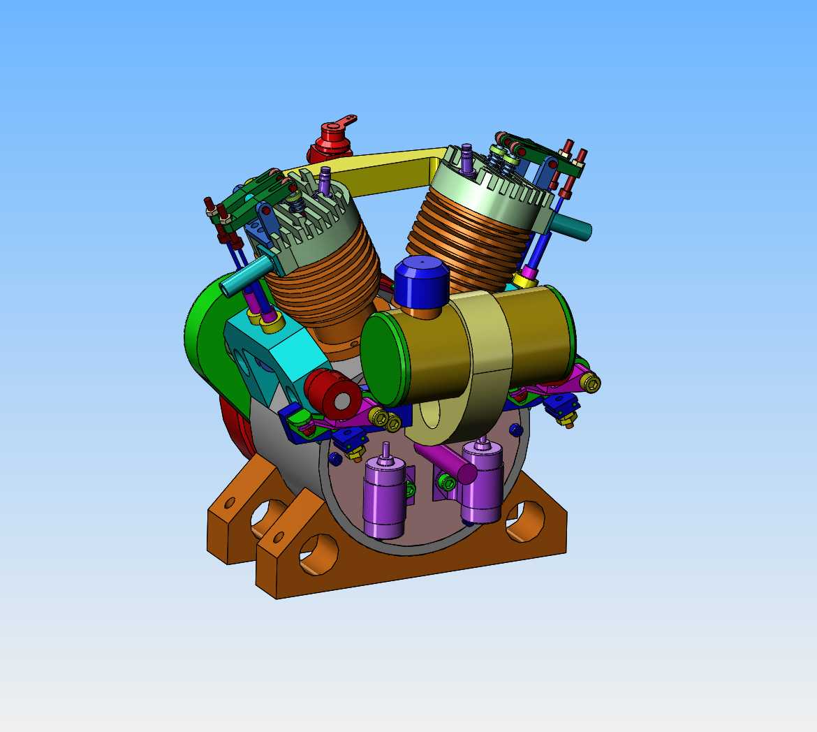
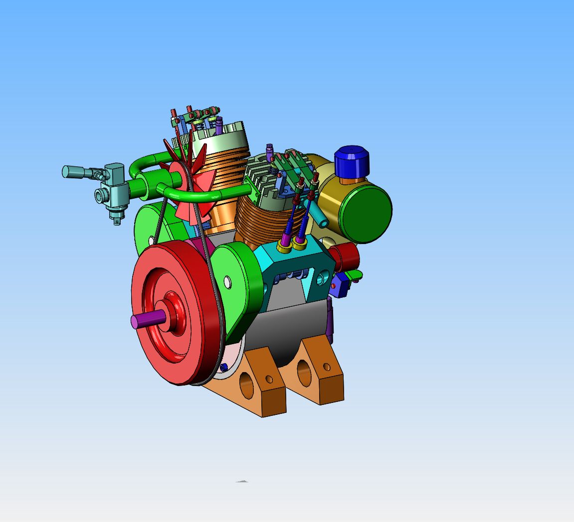
When you end up with the cooling fan and the carburetor both wanting to be in the same place, this is what you do. Looks wild and crazy, but I can't see any reason that it wouldn't work. I've got lots of things to do before I get to the point where I need to make this intake-carburetor-fan mash-up, so I've got a while to think about it.
z9nLMg.jpg
 
Hi Brian, this looks like you are sucking cold air over the intake mainfold, then blowing that past the engine, so the hot air will pre-heat the fuel tank and fuel. Is that a good plan? Or could the fan go the opposite side to blow the heat away from the fuel tank? Or maybe re-mount the fuel tank so it gets cold air, not hot? Off to one side perhaps? Not in-line with the exhaust ports?
Just ideas...
K2
 
The intake manifold doesn't give off any heat. The air blowing over the cylinder fins will pick up some heat, but nowhere's near it's heat saturation point. If the fuel tank heats up, I would be surprised. There really isn't any other good place to put a cooling fan.
 
Spent the first half of today drilling and tapping 18 holes in the crankcase and sideplates to get everything bolted together. Probably the next thing will be putting threaded holes and clearance holes in the cylinders.
EutOhK.jpg
 
Hi Brian, Thanks for post#54. I understand. - My only experience is with motorcycle air-cooled engines, where intake manifolds can get hot, and insulation is required to keep the heat from conducting to the Carburettor. So I had surmised that you wanted the fan there to help cool the intake manifold, by drawing air across it that then blew across the cylinders.
How will the exhausts fit?
This is another intriguing build - Thanks for posting your work.
Cheers!
K2
 
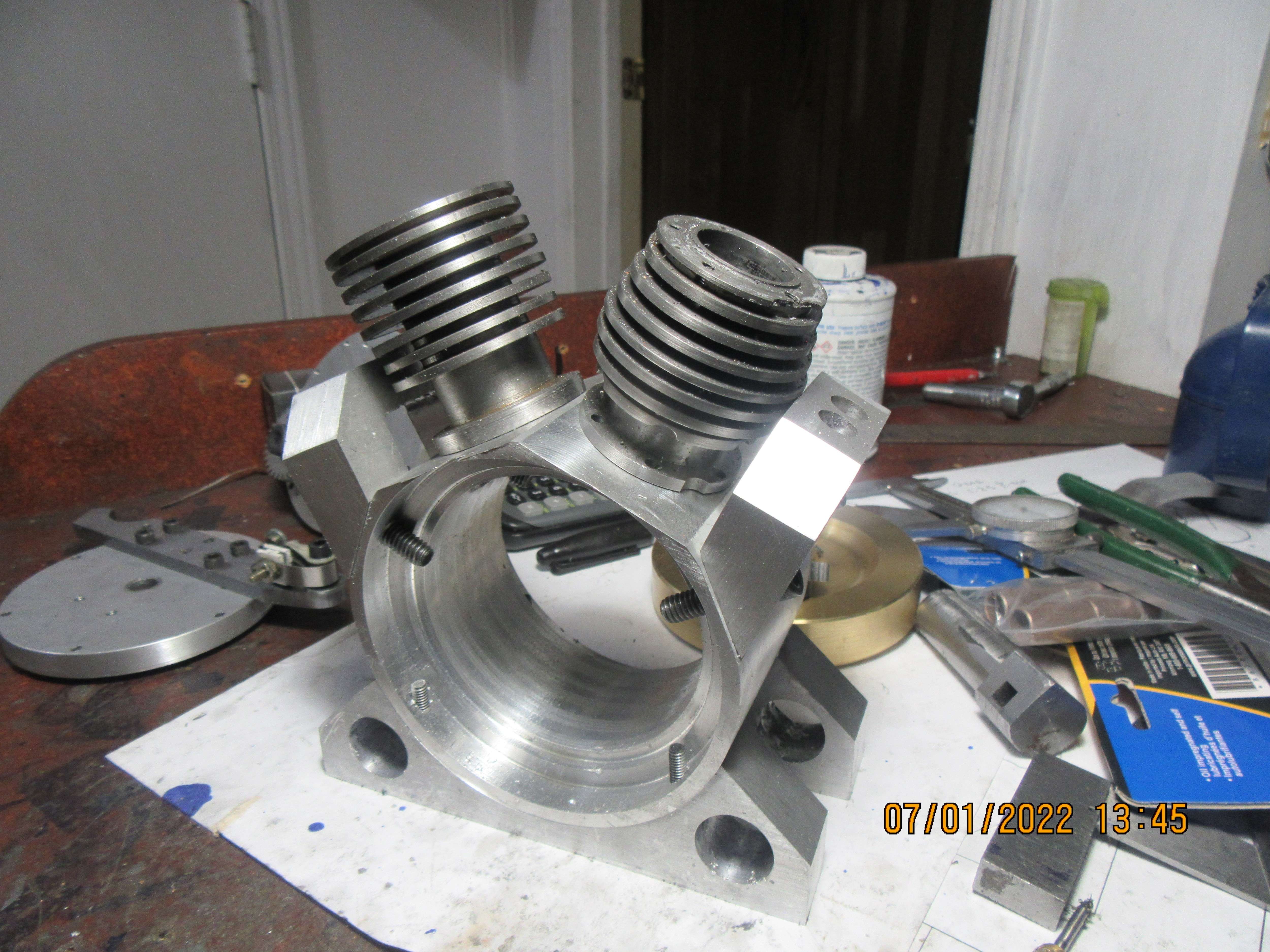
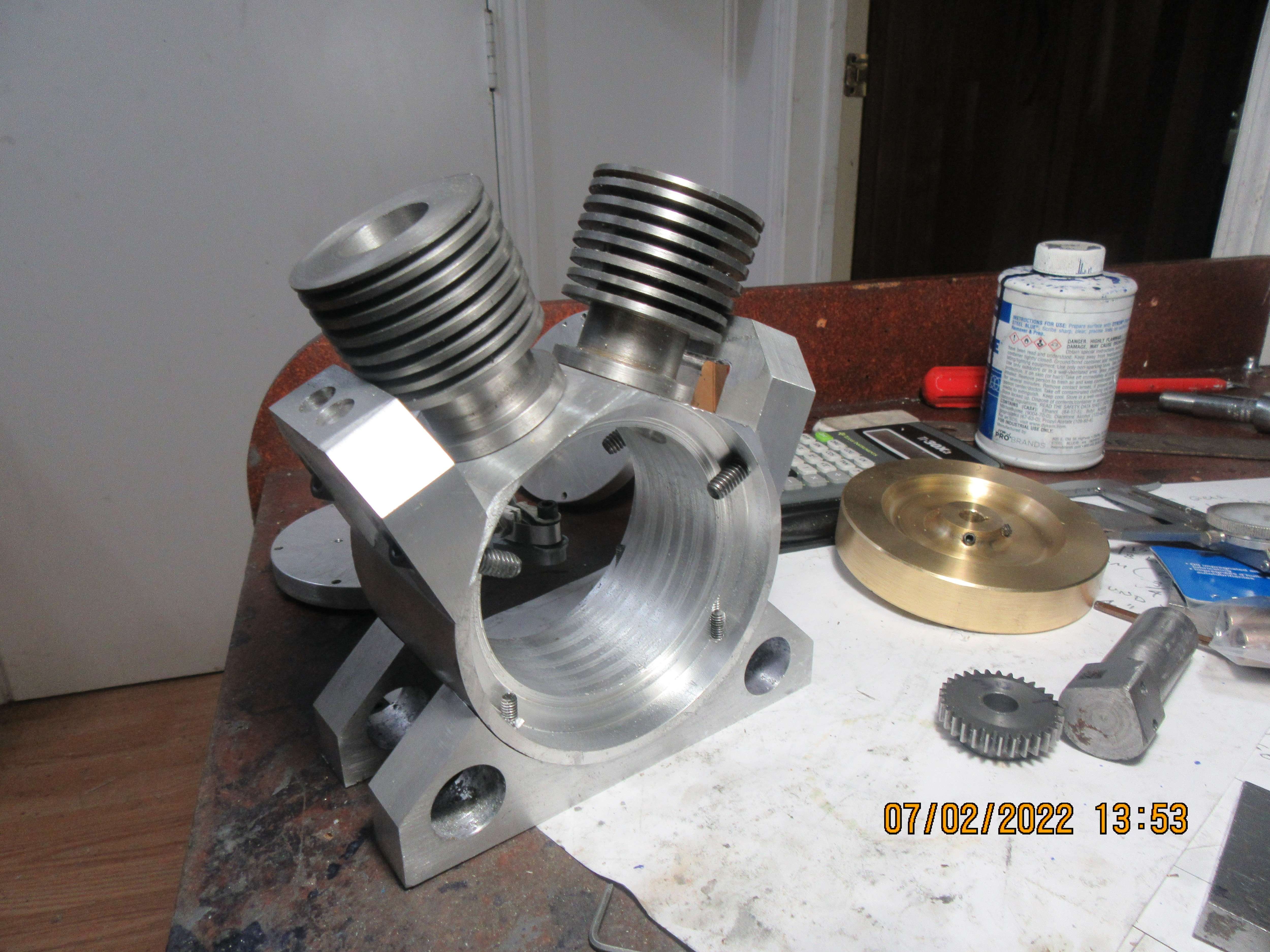
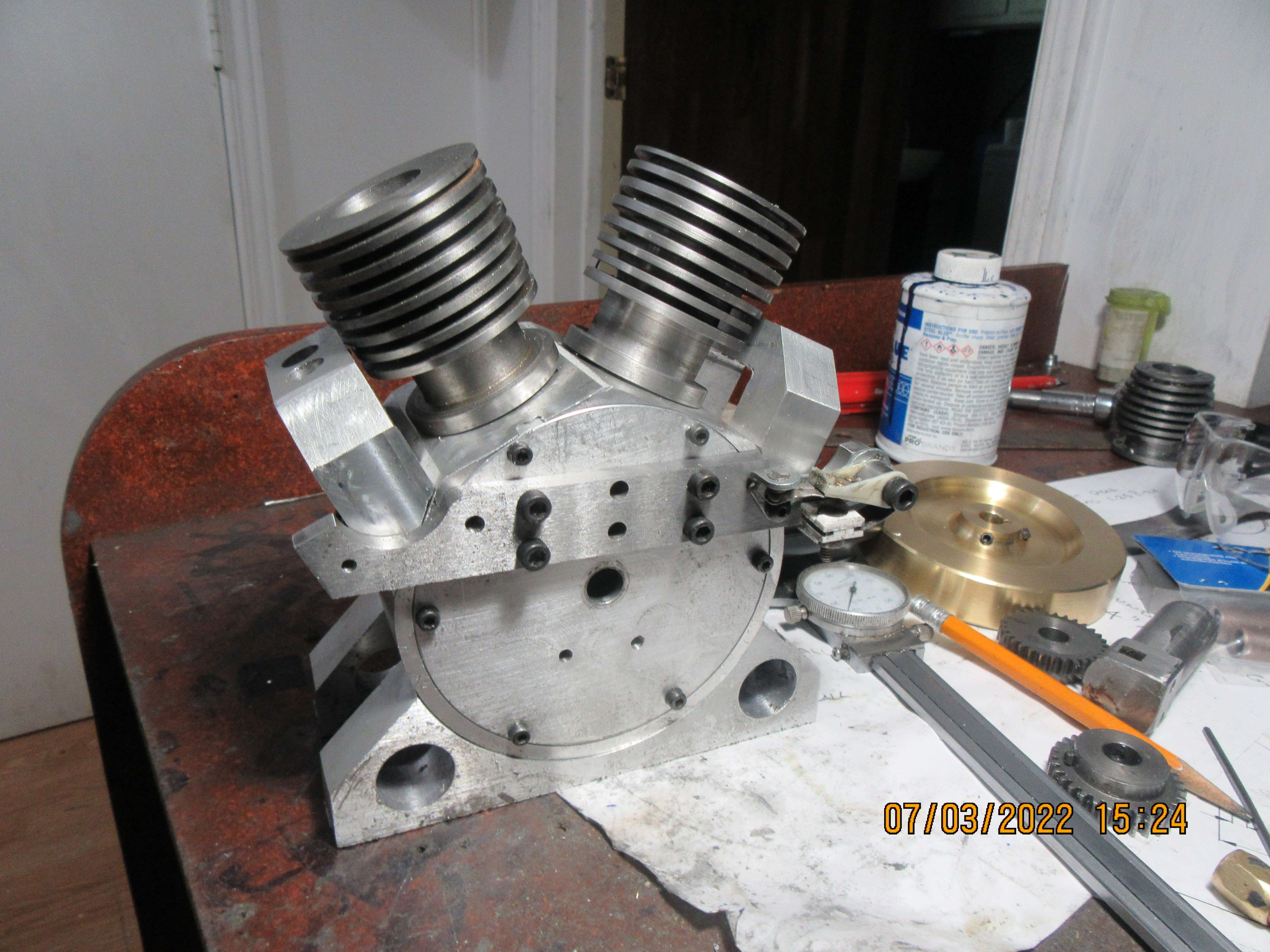
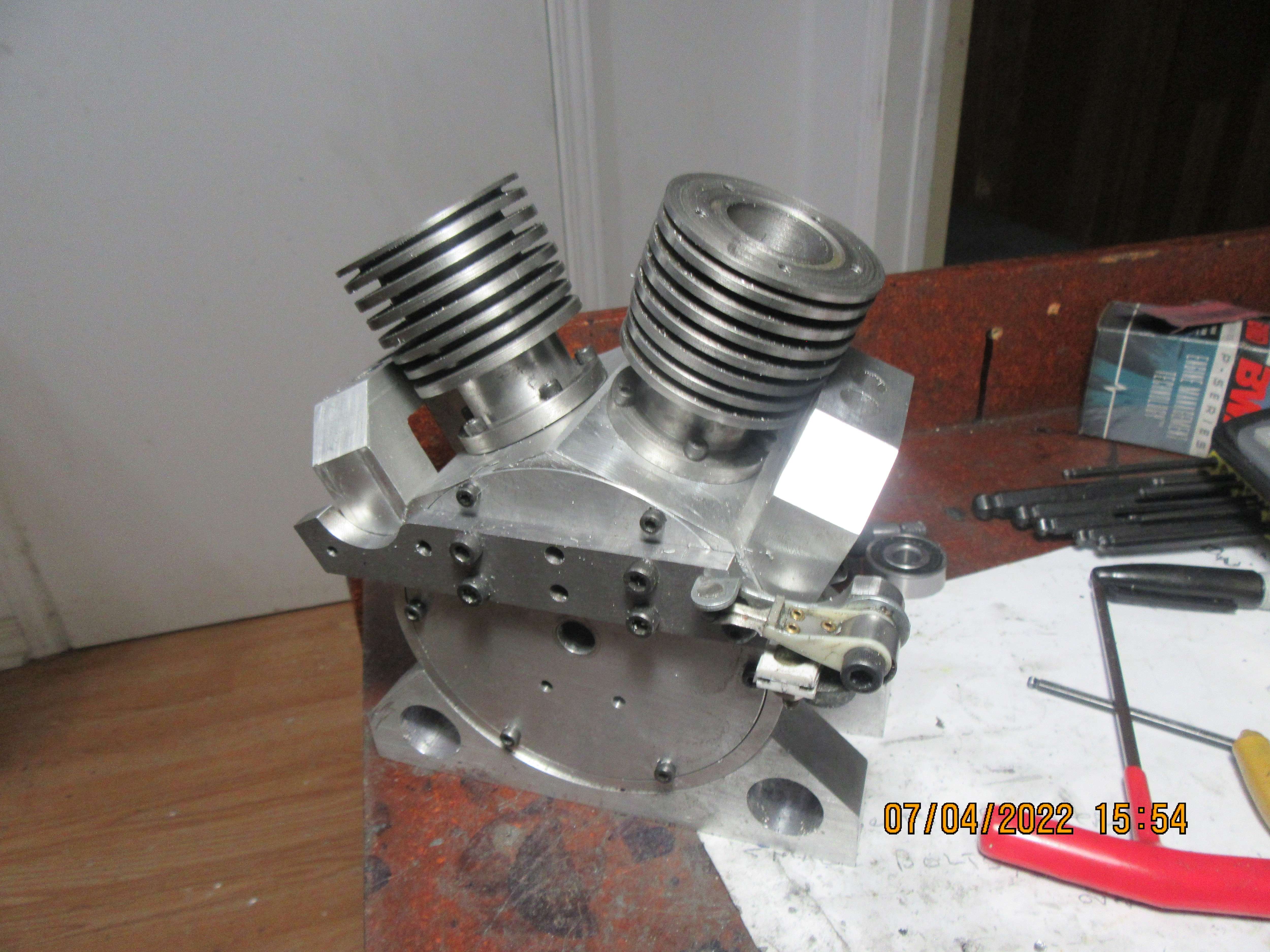
So, here we are with both cylinders drilled, tapped, grooved for o-ring head gasket seal, and bolted into place on the crankcase. Oh my, what nasty little buggers those socket head capscrews are that hold the cylinders in place. It would have been a lot simpler if I had cut the bottom cooling fin off each cylinder to give myself some more clearance. I didn't want to give up that cooling fin, so I shortened up one end of an Allen wrench and tightened them up, about 1/4 of a turn at a time. Ah well, it's progress.
N6HYR1.jpg
 
Back
Top