Transitional Engine

Home Model Engine Machinist Forum

Help Support Home Model Engine Machinist Forum:

This site may earn a commission from merchant affiliate links, including eBay, Amazon, and others.

glue-itcom

Well-Known Member
Joined
Apr 10, 2013
Messages
216
Reaction score
300
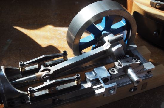
I've been making this engine for a long time, mostly down to the fact that the design is in my head and not on paper.


The basic idea is that it is a steam engine converted to run on gas and so something from around the late 1800's in basic principle - an agricultural engine.

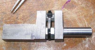
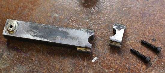
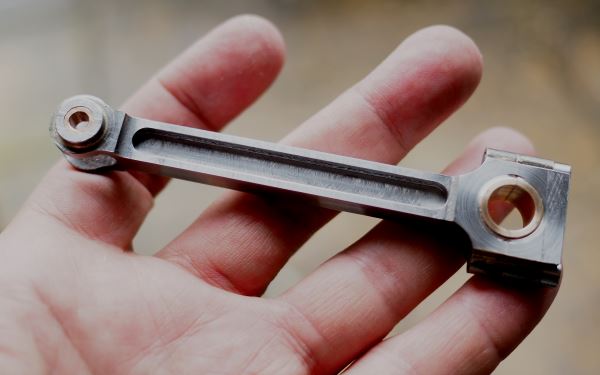
The conrod is a slider and so in 2 parts:

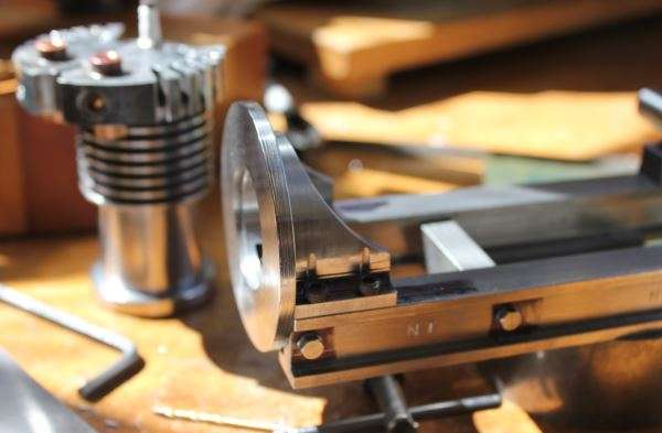
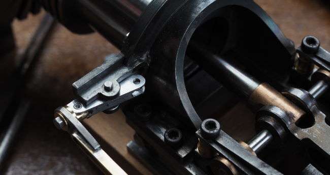
The exhaust valve is operated by an eccentric that has a pushrod in two parts and this works via a bellcrank that sits off the side of the crankcase:

The inlet will just be a poppet valve on a spring - I need to find a good source of springs at different rates.

A lot more images and details on my pages: http://www.glue-it.com/wp/gallery/engines/transitional-engine/
 
Thought I would post some more images showing the design and some of the machining steps

crankcase-012.jpg

The crankcase, ok not much of it, was machined from a solid piece of mild steel.

A lot of machining steps to get to this point and quite a few hours in the workshop:
http://www.glue-it.com/wp/gallery/engines/transitional-engine-crankcase/

crankcase-014.jpg

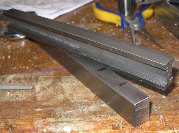
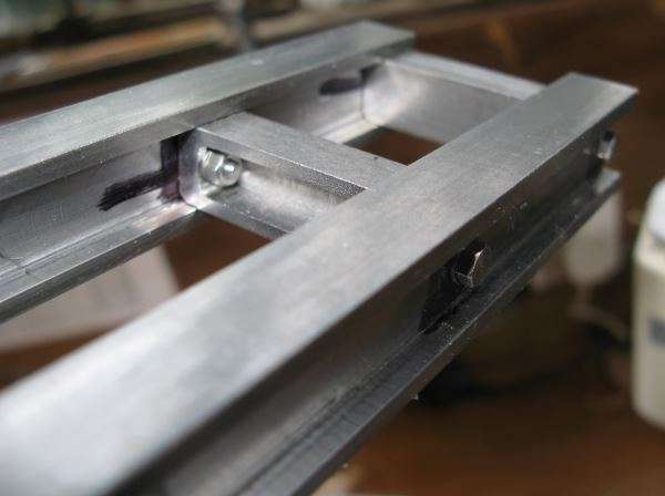
The crankcase bolted down to the I-beams.
 
The crankshaft was machined from a quite substantial piece of mild steel:
crankshaft-001.jpg
 
Lined up in the lathe for the first stage of machining
crankshaft-002.jpg


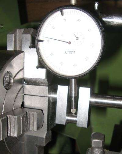
I used 2 nuts and a short piece of studded bar to support the crank for some of the next stages
crankshaft-009.jpg

The cable tie is there to keep the nuts in place when this is spinning, I didn't want this flipping out and hitting me.

just setting it up to ensure the final surfaces were all parallel
crankshaft-016.jpg


And it's all laid out in detail here:
http://www.glue-it.com/wp/knowledge/crankshaft/
 
Soldering doesn't have the strength for this application. I'd suggest TIG as opposed to other kinds of welding, since it has more concentrated heat (less warpage). Tom
 
Plus one on the TIG operation. More easily controlled heat application and a finer bead and fillet for scale. Brazing would be another possibility in this application as the joint is stronger than soldering, but it still involves more diffuse heat and the opportunity for warpage.

Neat project, I can’t wait to see the final results!

John W
Camp Verde, AZ
 
Silver soldering (silver brazing) would be my choice on a part like that, even with neat TIG you will get a fillet where you don't want it.

Having said that back in the day an engine bead made out of structural sections would more than likely have been bolted or rivited together. Pitty you put such a big fixing in already as a few small ones in each would have looked more scale.
 
I'm not really after scale, more just a look. The cooling fins on the cylinder are not very scale and the head is definitely wrong, just somehow it has a nice look to it with regards to proportions.
 
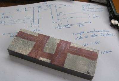
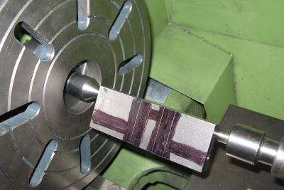
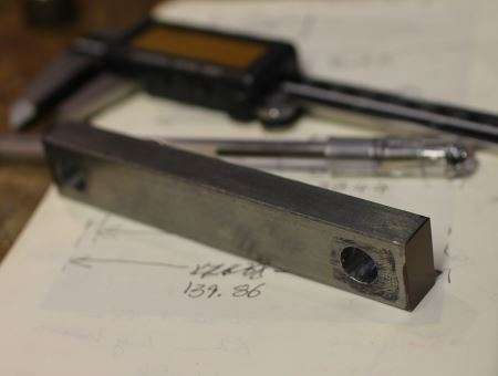
The conrod is a bit of a monster as I machined it from mild steel
transitional-engine-conrod-002.jpg

Several stages of machining, silver soldering
transitional-engine-conrod-004.jpg

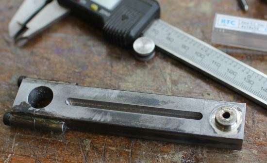
more machining
transitional-engine-conrod-003.jpg

and a lot more machining to get to here
transitional-engine-conrod-005.jpg

and on the engine as a two piece conrod with a slider it does look rather good
transitional-engine-conrod-006.jpg

there is a lot more to do on this engine and some parts need modification, some parts need to be thrown and to start again
 
I changed all of the design for the cam operation and decided on an eccentric. This then took me to the idea of using a bellcrank to align the pushrod.
transitional-engine-eccentric-009.jpg

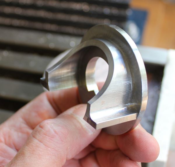
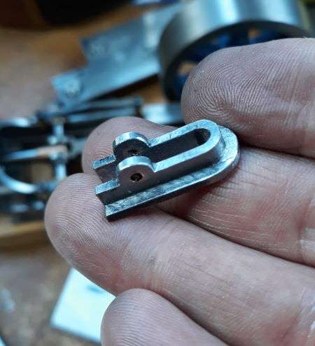
The bracket itself took me some time to machine

transitional-engine-eccentric-001.jpg

I still have a lot to do and this engine is a labour of love that I work on when I get inspiration. Best regards, Nigel
More details of the build are here: Transitional Engine
 
I just rejoined this group and one of the first posts i read is about this model. My dad is busy restoring a full size engine that with the flip of a lever you could run it on steam or gas. The picture that i attached is not the one my dad is working on but it is the exact same.
The engine weighs aprox. 2800 pounds.

chuck
 

Attachments

  • P03_Gardner.jpg
    P03_Gardner.jpg
    14.7 KB
Hi, that's interesting, if you get a chance for more images of the restoration then they would make a great post. Thanks, Nigel
 
Back
Top