Torque needed for MT3 drawbar?

Home Model Engine Machinist Forum

Help Support Home Model Engine Machinist Forum:

This site may earn a commission from merchant affiliate links, including eBay, Amazon, and others.
Ah, I have not seen a drawbar like that before. I am still convinced that something is wrong, but I don't know what to advise, except that using Loctite is not really a solution. Have you tried some engineer's blue on the tapers to make sure they match?

In removing a tight morse taper tool, I find a tap with a big hammer more effective than a whack with a little one.
 
In removing a tight morse taper tool, I find a tap with a big hammer more effective than a whack with a little one.
Agreed. A good clonk with a heavy chunk of brass. Not a deadblow hammer, it absorbs the shock too much. Repeated tapping with the bearings in the same place is harder on them than a single slightly harder tap.
 
I really don't think anything is wrong, and my loosening problems stem from the drawbar being barely tightened. I doubt I'd see these problems with an R8 spindle since the drawbar is tightened down much harder with those.

I think I've worked out an alternative method for releasing the tool from the spindle, and will try to post a couple pictures later this evening.
 
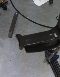
For the MT3 spindle release I took an 8" C clamp and modified the modified it to fit between the spindle and tooling:
clamp1.jpg


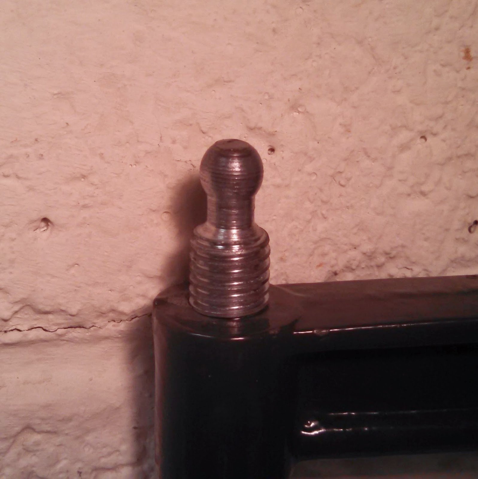
I then removed the pad from the clamp's screw, leaving just the ball end:
cclamp.jpg


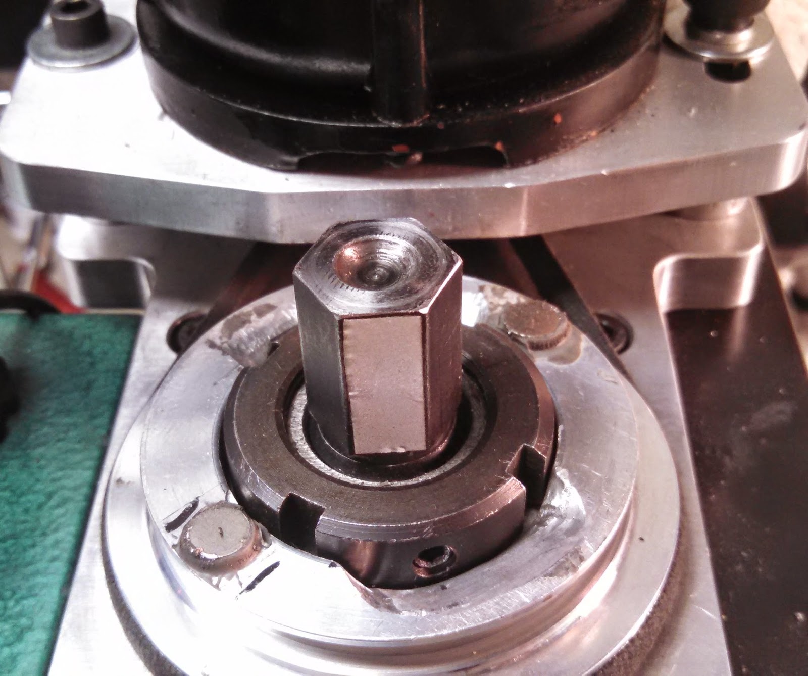
Then I turned a partial spherical dimple in the end of the drawbar:
drawbar.jpg


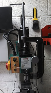
Now when I want to release the tooling I loosen the draw bar, mate the clamp's ball end to the drawbar dimple, slip the bottom of the clamp between the spindle and tooling, and tighten the clamp until the tooling is ejected:
clamp2.jpg
 
Hi Zoltan
Excellent solution to release morse taper from spindle.
This can be used on all lock bolts regardless of what the thread pitch.
Having a number of different pitch lock bolts this helps make it simpler.
Well Done Zoltan

Eric
 
I'm sorry, but I'm really at a loss to understand why people bother with all these creative ways to remove MT tooling. If you loosen the drawbar a thread or two and give it a whack, how does that impact on the bearings? Think about it. The only thing you whack is the drawbar and the only thing it is touching is the taper. The bearings are not part of the equation and if the spindle does move down at all in unison with the whack, it is designed to slide up and down anyway so the bearings are not impacted. There might be a bit of a jolt on the spindle rack gears but nothing's going to get damaged as it is free to move.

We are talking about a sharp whack to provide enough inertia to pop out the taper, not belt the machine to pieces.
 
The taper is locked into the spindle, so if the tool doesn't come out of the taper, the force is transferred to the spindle, and then to the bearings supporting the spindle.

I've yet to have a problem though. I have to whack the drawbar on my lathe surprisingly hard to get my MT collets to release, and after 3 years of doing that, I took the head apart to make sure I wasn't doing damage. Not a single sign of problems with the bearings. Properly adjusted bearings might be a factor though. For oil lubricated tapered roller bearing there shouldn't be any slack so the weight of the spindle can't accelerate axially when the draw bar is struck and so the rollers are properly seated all the way around and not concentrating force on the roller at the bottom. In a vertical mill, gravity pulls the top bearing down into full contact with it's race, so it's not a problem there.

Your mileage may vary.
 
I'm sorry, but I'm really at a loss to understand why people bother with all these creative ways to remove MT tooling. If you loosen the drawbar a thread or two and give it a whack, how does that impact on the bearings? Think about it. The only thing you whack is the drawbar and the only thing it is touching is the taper. The bearings are not part of the equation and if the spindle does move down at all in unison with the whack, it is designed to slide up and down anyway so the bearings are not impacted. There might be a bit of a jolt on the spindle rack gears but nothing's going to get damaged as it is free to move.
The spindle is only supported by the bearings, and does not slide up or down in the bearings. So any impact to the spindle is directly transmitted to the bearings. In fact, due to bearing preload, the entirety of a hammer blow to the drawbar is absorbed by just the top bearing.
 
I've yet to have a problem though. I have to whack the drawbar on my lathe surprisingly hard to get my MT collets to release, and after 3 years of doing that, I took the head apart to make sure I wasn't doing damage. Not a single sign of problems with the bearings. Properly adjusted bearings might be a factor though. For oil lubricated tapered roller bearing there shouldn't be any slack so the weight of the spindle can't accelerate axially when the draw bar is struck and so the rollers are properly seated all the way around and not concentrating force on the roller at the bottom. In a vertical mill, gravity pulls the top bearing down into full contact with it's race, so it's not a problem there.

If you're using tapered roller bearings in your lathe that's probably why they were fine even if you hammering on them. They have a line contact with the race, as opposed to a ball bearing's point contact, so it takes significantly more force to damage the race or rolling elements. My mill uses deep groove ball bearings, and the original top bearing was already developing a slight indexing when I upgraded them, hence my reluctance to continue hammering on the drawbar. If my mill used tapered roller bearings I wouldn't have much issue just hammering the drawbar.
 
Try Googleing the term "brinelling" along with "bearing's", there obviously not referring to the barely automotive quality bearings in something like the smaller Seig mills. But for very high precision spindle bearings it can take as little as 4 ft. pounds of shock force to get that brinelling process started. It's NEVER a good procedure to subject any bearing to any type of shock force. There not designed for or intended to take that. Having a morse taper internal taper on any mill today without also having a built in screw type ejection to release the male taper is just amazingly poor design and engineering in my opinion.

Pete
 
Hi All
I have followed this thread with interest from the start on the varied ideas and opinions.
Pete sums it up nicely with the "If you bash them you can bust them" approach.

The attached photos will show my approach to the problem.

Eric

1-pull.jpg


2-pull.jpg


3-pull.jpg


4-pull.jpg


drawbar-release.jpg
 
Hi All
I have followed this thread with interest from the start on the varied ideas and opinions.
Pete sums it up nicely with the "If you bash them you can bust them" approach.

The attached photos will show my approach to the problem.

Eric
I love this solution. It's elegant.
 
Car and trucks use taper roller bearings in the wheel hubs and have about 3 thou floating clearance when assembled and they put up with severe punishment from the road surface without any diverse affects so I don't think a whack of a hammer to release the morse taper in the spindle would harm them.
Vince
The X2 comes stock with deep groove ball bearings. I've upgraded my mill to angular contact bearings. Neither tolerate shock loads nearly as well as low tolerance tapered roller wheel bearings.
 
Sorry I just presumed your spindle ran on taper bearings (should have read the whole thread)
Vince
 
I wonder how difficult a retrofit to taper bearings would be
 
I wonder how difficult a retrofit to taper bearings would be

Hi to All with apologies to Zoltan.
Just had to run with this
This is not to difficult But will need a couple of mods See attached files.
You will need to fabricate brass shim shields to help retain the grease in the bearings.
The taper rollers are 17.25 mm wide as opposed to the Ball races that are 16 mm wide
The Shim is .25 mm THICK NOT as shown on the file so you need to Bore the outer bearing housing another 1.5 mm deeper OR Grind off 1.5 mm from the inner race of the bearing.
Grinding the inner race must be perfectly true and square to the bore.

To swap for Shielded angular contact bearing is a straight swap with no mods.
Either method will give much better performance than the original ball races.

Eric

mini-mill-headstock-spindle-bearings-dimensions-3.jpg


sheild shim.jpg
 
You don't need to bring the bearings or bore the bearing seat deeper. You only have an extra 1.5mm extra on each end and it's fairly easy to deal with.

For the shields I prefer to use HDPE from an empty milk jug. It's very easy to cut using a simple compass cutter. It works very well.

Of you go to tapered roller bearings don't just buy wheel bearings as they have a max TIR OF 0.0007". Instead spend a little extra and buy P6 grade (or C grade) bearings from your local bearing supplier as they only cost a little more but have a max TIR of only 0.0002”.
 
The part number of the bearing yoiu want is a 30206 - that's an ISO standard number and will be recognised at any bearing supplier. Buy a quality brand like SKF, FAG or even NTN. In a spindle application the bearing should be carefully adjusted into a very small preload condition not only for maximum load capacity but for maximum precision as well. The 30206 manufactured by SKF has a maximum side runout of 10 microns (0.01mm or 0.0004").

If you could somehow use it, the 32006X is a higher precision bearing and would normally be the choice for a spindle bearing. Dynamic load rating is the same but the critical dimensions are 30mm ID 55mm OD and 17mm thick.
 
Per the SKF catalog it looks like their automotive grade 30206 has a max TIR of 0.0007".

The 30206 is only if you have a MT3 spindle. If you have a R8 then the bottom bearing is 32007.
 

Latest posts

Back
Top