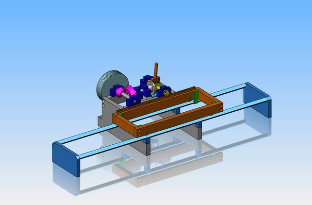
Rotary motion to reversible linear motion

Home Model Engine Machinist Forum

Help Support Home Model Engine Machinist Forum:

This site may earn a commission from merchant affiliate links, including eBay, Amazon, and others.
There is still something I'm not understanding here. When I go to paste a .jpg of a photograph, I click "insert image" then I click "by url" and then click the picture I want inserted.--The picture shows up, but then when I save my post the picture reverts to a link that gets posted, not the picture I wanted.---HELP
 
Last edited:
You don't click the picture.

Copy the url from where you are hosting them

Click the insert image icon

Click the right hand link icon that I have ticked

Paste the url into the box.

Click insert

It has been like that for years.
 

Attachments

  • insert.JPG
    insert.JPG
    16.2 KB
Brian,
The "ATTACH FILES" button(L/H side
below the text window. Click this then select the pic you want from your computer and you are done.
Cheers
Andrew
 
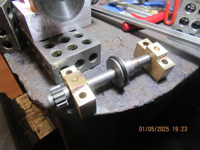
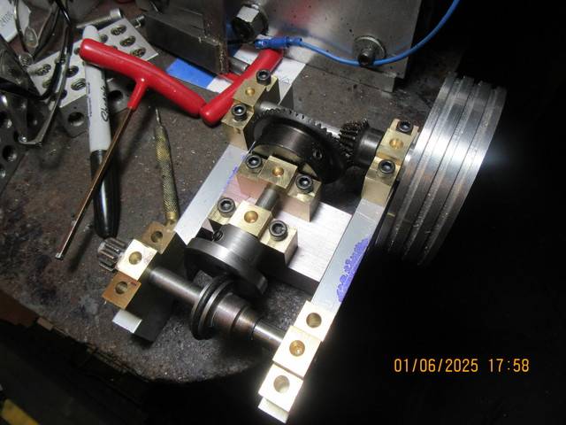
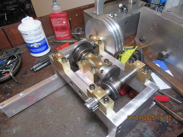
Today all of the shafts and gears are mounted and the aluminum frame which supports the gears and shafts is complete. I'm still having trouble pasting a picture, but I'll give you the link to see where I am at currently. I'm very pleased so far.
https://imagizer.imageshack.com/v2/640x480q70/922/gPfutG.jpg
 

Attachments

  • 2025-01-07 ALL SHAFTS AND GEARS MOUNTED IN PLACE 001.JPG
    5.8 MB
gPfutG[1].jpg

:cool:
I just clicked "Attach files" then pasted the link into the search window.
picture.jpg

Did not even bother to choose the proper folder or anything, just insert the link into the File name form on the bottom.
Does that help anything?
Greetings Timo

p.s. anyway obviously we can see the pictures if we care.
 
Brian, Look up "Torotrak" for another interesting drive. = I have never got around to making one, but I like it!

It cleverly uses a sun and planet gearbox to add/subtract motion to a drive, thus making a reversible and variable speed drive. Great for industrial uses and lawnmowers!
K2
 
I did a similar setup for a clutch and variable drive for a little gauge 1 loco I did, powered by a tiny 4stroke engine, and it still works a threat 4 years later...

on the last picture of the final version you could see a ball trust bearing and a large knurled brass ring threaded to set the proper pressure of the o ring in front of the polished steel disk.
 

Attachments

  • variable friction drive (1).JPG
    variable friction drive (1).JPG
    2.5 MB
  • outil à rainures (3).JPG
    outil à rainures (3).JPG
    2.5 MB
  • montage à réaliser (4).JPG
    montage à réaliser (4).JPG
    2.1 MB
  • IMG_0013.JPG
    IMG_0013.JPG
    2.7 MB
  • boite de vitesse V2 (2).JPG
    boite de vitesse V2 (2).JPG
    2.1 MB
I showed these images because they're very close to what Brian is doing.
and in my opinion, the trickiest part is adjusting the pressure of the roller on the rotating disc, I did several different set-ups before finding the right formula with the adjustable ball plate.
@Steamchick
I don't want to interfere with Brian's thread any further, so I'll just reply as follows :
the engine is a 4-stroke with 12 mm bore and 12 stroke (ie 1.35cm3), that is quite small!
my loco has been running every month or so for 4 years at my club, so I have plenty of videos on my playlist:
 
On snow blowers that use this type of drive, the the driven wheel (with the rubber) have some type of toggle engagement that keeps the wheel against the drive disk. Meaning that the driven wheel and shaft need to be able move in and away from the disk.

Sid
 
I showed these images because they're very close to what Brian is doing.
and in my opinion, the trickiest part is adjusting the pressure of the roller on the rotating disc, I did several different set-ups before finding the right formula with the adjustable ball plate.
@Steamchick
I don't want to interfere with Brian's thread any further, so I'll just reply as follows :
the engine is a 4-stroke with 12 mm bore and 12 stroke (ie 1.35cm3), that is quite small!
my loco has been running every month or so for 4 years at my club, so I have plenty of videos on my playlist:

THAT is one of the best model engine projects I have ever seen !!!
 
Last edited:
The bobbin arrangement I used on my boat does not have the variable speed drive, just forward/Neutral/reverse. However a feature of my configuration (not original? - is anything in this century really new?) but a simple use of the prop shaft as the centre of rotation for the "driven wheel", that connects to the prop-shaft by a belt drive (it could use a gear drive). It does mean the actuation lever has to cope with countering the torque off the reaction from the prop-shaft, but the servo in my model boat does that easily. I must take a photo... This is a difference from the fixed secondary (out-put) shaft used by Brian.
But I think Brian's configuration is good and robust and once set should not need frequent or variable "contact pressure* adjustment. - Except for wear/fatigue of the O-ring. In fact I believe Brian could use a steel-on-steel drive, with suitable contact pressure and lubrication:
Where I and others use an elastomer O-ring as the "driven tyre" from the smooth driving wheel, or in my case a slightly knurled driving wheel, the Torotrak drive manages with just a steel-on-steel contact at a suitable contact pressure from Belville washers, or hydraulic cylinder, depending upon the torque required and size of transmission.
To increase friction at the contact point between steel-and-steel Nissan developed a curious (Unique?) lubricant for their CVT transmissions that use steel belts and steel conical wheels. This "clever" lubricant is based on Automatic transmission fluid, but had "clever" molecules that physically "bond" under extreme pressure, then release when the pressure is removed. This means at the point of contact the lubricant ceases to lubricate but acts as a high-shear-strength material between the steel surfaces. Thus it successfully resists the shear and slippage, which reduced heat production and eliminates sliding contact wear. Thus the Nissan CVT became a fairly successful transmission where - with correct maintenance, servicing and changing of the fluid after a suitable service life - Many transmissions thus had a very long service life providing the correct "high friction" CVT fluid was used, filters cleaned and fluid changed at the service interval. (There are other "opinions" that I shall not debate here!). Such a fluid can achieve comparably very high transmission (friction) values of steel-on-steel contacts, without the high-pressure contact that would cause surface metal fatigue of the steel. I understand that Torotrak have produced transmissions for industrial service lifetimes that use direct steel-on-steel contacts in their variator control wheels between discs, and these are using common steels and manufacturing to the materials, finishes and durability of rolling element bearings.
All this suggests that the rubber wheel is not necessary on Brain's drive, if he can balance the contact pressure (of steel-on-steel) with the torque transmission required from the drive.
Excuse me Brian for such a long comment in your thread? - I can remove it if you wish?
K2
 
Not the configuration you are making Brian, but I like the application of this type of variable speed friction drive to the summation that an epicyclic (smell-check could not handle that word!) gearbox achieves, something like the Torotrak drive...
An old electric screwdriver has an epic click gearbox that may provide a starting point? Or a bicycle hub gearbox?
I must see if I can work out a configuration and find an application!
Keep up the good work Brian! Just glad to be reading your contributions after your knee sabatical.
K2
 

Latest posts

Back
Top