sorry I haven't been on for a while but this will be my final update on this version of the tiny stirling engine.
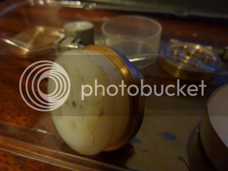
Here is a pic of the lightened displacer, as I said, it didn't make it that much lighter to be honest, maybe 30%. Apologies for these pics, I was just having one of those days and not a lot would go right!
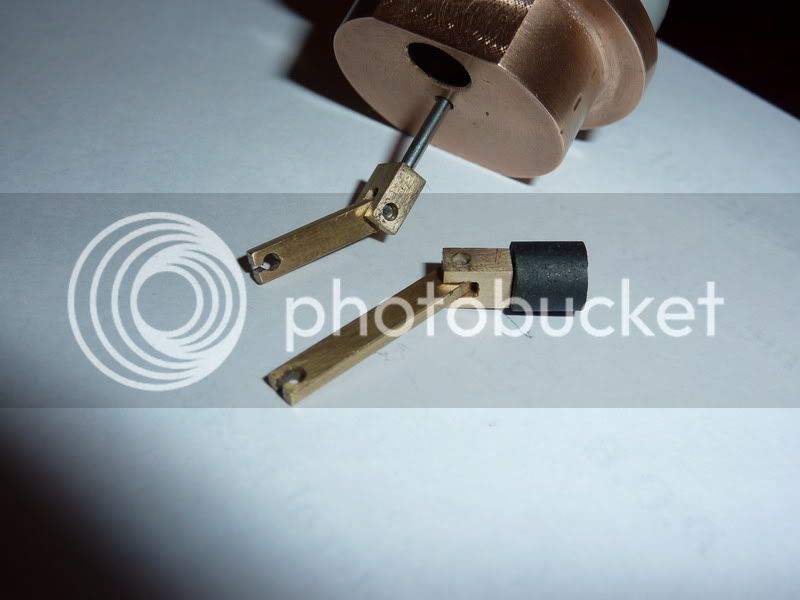
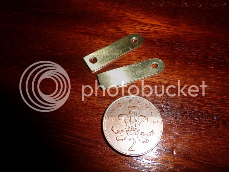
Next was the piston as I said below, then the two small ends. I didn't have any 1/8" dia brass (thought I had some brazing rod but couldn't find it) so I made some square versions from some flat 1/8" brass strip. I also decided to make them a tad wider than 1/8" in the other plane so I would have more room for the slot. I selected the right drill to give a nice push fit for the pins so everything together with a pretty easy press fit. Here are pics of them assembled to rods. I was running a bit short of time by this point so sorry, I didn't get any machining pics but there wasn't much to show.
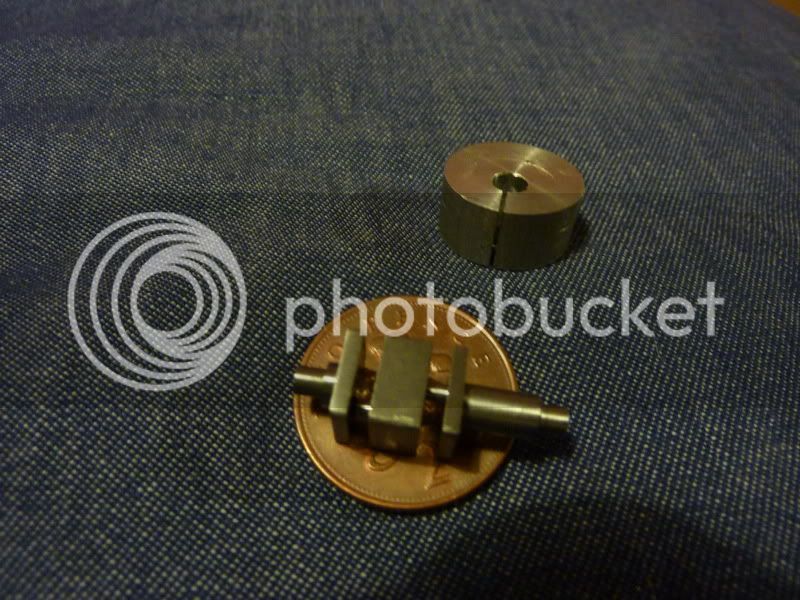
The last piece was the crankshaft. I started making this from 3/8" square brass and quickly screwed the diameter up resulting in a wobble on the flywheel before I'd even started on the journals. So that bit got scrapped, then I could only find 3/8" square steel. This was bought about 13 years ago for my 5" gauge Sweet Pea locomotive project that hardly got started. It actually cut nicer than the brass which I was pleased about.
This was a tricky component to make. I had to decide on the right order of machining operations so as to leave enough structural integrity so that it wouldn't bend.
The first job was to centre it in the 4 jaw. That wasn't too difficult as I found out 3/8" was the smallest size my 4 jaw would go down to - this became a problem later. I faced each end to overall length then turned the longer plain diameter for the flywheel and the 1/8" spigot for the bearing. Turned it around and did the same on the other end so each end was concentric (within the accuracy of my 3 jaw - good enough).
That's when I was going to put it back in the 4 jaw to offset turn the journals but of course I couldn't, the 4 jaw was too big, when I tried to get the offset the jaws just clash into each other.
So I decided on a fool proof way of getting the 1/8" offset to give me 1/4" stroke. I just put a bit of nylon in the 3 jaw, offset by 1/8" with a bit of packing under 1 jaw, centre drilled and drilled a hole for a tight fit on the plain diameter, then put a saw cut through to the hole along the length of the offset bush. I then clamped the crankshaft in the bush in the 3jaw. I was struggling to get it to grip the shaft but when I did, I took too big a cut and it mangled the nylon and pulled the shaft out - luckily or miraculously no damage. So I decided to make an alloy split bush instead by the same method. This gripped much better.
I turned the journal furthest away from the chuck first, then the one nearer in, as I said so it still had enough strength. This worked pretty well except I possibly got a little frightened as it was approaching 1/16" diameter and stopped a little large.
When I took the crankshaft out, it had turned out well except I don't think it had achieved the 1/8" offset I required. How could this happen? I just assumed if I put 1/8" packing under 1 jaw that would do the trick, or did I need to work some geometry out? I've never even thought about it to be honest!
This was on Christmas eve or the night before I think so I didn't have time to make a new one, I just thought I'd have to try it. The effect this would have is to leave dead space at the top and bottom of the displacer though - not good.
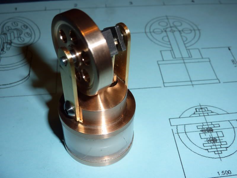
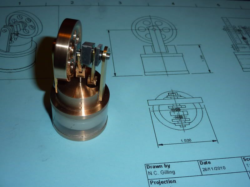
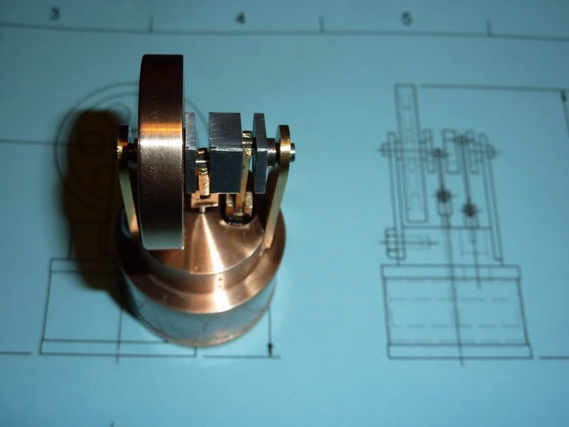
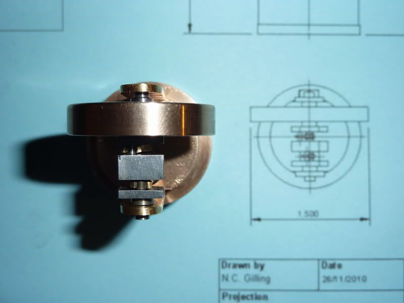
I thinkit was on christmas eve that I assembled the engine. Here are the assembly pics.
I forgot to mention, the other issue on the crankshaft was, I got carried away and forgot to make the journals the correct width. I thought ah, it'll be near enough jsut being the width of the parting tool - that way I only had to do 1 plunge for each. But it wasn't quite - When I assembled, one of the bearing uprights was to be super glued onto the top plate but to get it free running, I had to put a couple of shims under it to prevent metal to metal contact with the crankshaft and one of the rods - luckily I had allowed enough clearance on the length of the crank main bearings to allow this.
The other bit I found difficult was putting the rods onto the journals - these were the ones that had slits in the big ends to bend out, over journal and back in. With hindsight, I think I needed bigger slits. The plan was to bend them back with the long nosed pliers but I couldn't get in with those. I might have been able to do it resting on something and acouple of taps with a hammer and thin piece of steel. Not a great way of attaching the big ends really I don't think. May have been better building a crankshaft up of 3 or 4 bits but I thought I'd try to be clever and make from one piece!
The engine seemed very free running, I tried it on top of a flat bit on the heated towel rail and couldn't really get a peep out of it. It span over faster (10 or 15 revolutions) in the direction of running and only 4 or 5 in the opposite direction but nowhere near running I don't think.
Tried holding it over a tea light too and that was no different.
I think there are a few reasons it didn't run. The first, was the crank didn't have a long enough stroke leaving too much dead space in the system. Secondly, the fit on the displacer rod and piston could have been better. Thirdly, friction was possibly still too high even though I thought it was free running enough. The fourth could be the weight of the displacer, although the assembly seemed fairly balanced to me, it didn't seem to settle in any particular place. It had the weight of the piston and pin etc on the other side. Maybe the flywheel was also too heavy. If I make another, I will address all of these issues and hopefully have a runner.
I could provide drawings but I don't think anybody would want to risk spending the time and effort making something that might not work so I'll wait until I've built a working version.
My dad seemed happy with his present. Put a copy of the general assembly drawing wrapped up with it so he knew I'd design and built it with the intention of giving it to him for Christmas. I was gutted to have to give him a non working model though, if I do make a working version his will be swapped for it!
Nick





![DreamPlan Home Design and Landscaping Software Free for Windows [PC Download]](https://m.media-amazon.com/images/I/51kvZH2dVLL._SL500_.jpg)


