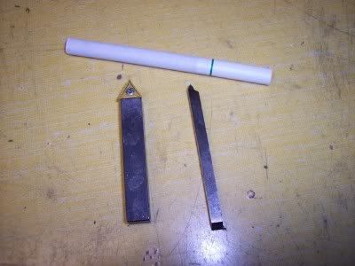
Threading Bits

Home Model Engine Machinist Forum

Help Support Home Model Engine Machinist Forum:

This site may earn a commission from merchant affiliate links, including eBay, Amazon, and others.
I never use inserts so I know almost nothing about them. I looked at the pictures of the inserts in the last link and what I see are flat top inserts with chip breakers. They have to be flat top when they can be used either right or left hand and can be rotated to three different positions, so no back rake is possible.

Your quote earlier that the slope on the insert was built in would make me think that the insert would be thinner on one side than the other and that should be noticeable on the picture of the insert with two adjacent cutters

Further on my example of a bit with a side rake having the right side at the wrong angle and give an incorrect thread form if you cut the full thread with a single pass. If you cut that same thread with two passes you reduce the error by cutting with shorter portion of the sloping edge. But, no matter how many passes you take, if the cutter angle is wrong the thread form will be wrong except it will be in small steps.

I know that back and side rake improves the performance of normal turning tools but you also have to have both left and right hand tools. I am just having a hard time getting to the idea of cutting with both sides of a tool with a sloping top.

The only other approach I can see is to take very small DOC and then ignore the small error.
 
Stan said:
Your quote earlier that the slope on the insert was built in would make me think that the insert would be thinner on one side than the other and that should be noticeable on the picture of the insert with two adjacent cutters

I couldn't find a good picture of a threading insert, with rake on both sides. They can do it though because the inserts are molded (I have seen them before, ISCAR I belive), so they don't have to grind them, thus just about any shape is possible.

take a look at these two inserts rake all the way around.

5505130.gif


5601249.gif


Stan said:
The only other approach I can see is to take very small DOC and then ignore the small error.

It's all relative, without breaking out the graphing calculator and doing a few hours of derivations, I can say two things with certainty.

1. the closer the compound is to 30 degrees the smaller the error will be.
2. the less rake you have the small the error will be.

The other thing to our benefit, is that the threading system has tolerances of a few thousands so I bet a standard bit with a few degrees of back rake will make a thread that is still within tolerance.


I'm loving this thread!

Now my 2¢ worth...

At work I use the the multi tooth inserts. They are run at 300SFM,
.005 depth of cut and flooded with coolant.
Pic297.jpg

The machine is programed to advance the tool on a 29° angle and it works
beautifully for production manufacturing.

At home the rules change.
Depending on the thread depth and size, I use one of these tools.
ThreadingTools.jpg

Surface speeds are half, 150SFM and the cutting fluid is nothing more than
a little cutting oil brushed on between cuts.
For model scale threads I have never found a need for the 29° compound advance.
I go straight in with no problem.

The very first single point threading job I did at home was making a new
mixer needle valve for a 60 year old hit and miss engine. It turned out to be
this:
First%20Thread.jpg


Single point threading is not a Black Magic craft!
If you can grind a piece of HSS to a 60° included angle, you can cut model
scale threads.

The information that has been posted here is dead on PERFECT for job shop
machines and practices. It all converts very well to the home shop when it
is scaled down to hobby machine capabilities.

Great information Dan!
Please keep it coming!

Rick
 
Stan,

I found the image I was looking for (make sure you exapnd it to full view).
http://news.thomasnet.com/images/large/006/6025.jpg

As you can see in the image it's a threading insert with rake on both sides. This can be accomplished with inserts, because they are molded. Unfortunately we can't easily grind a HSS bit like this. We can however make one side of the the bit have rake (like the one I posted above).

If your interested, Sandvik made the video below showing how inserts are made.
[ame]http://www.youtube.com/watch?v=al0xryL1vjI[/ame]
 
A couple of things have transpired regarding my confusion about tool bit rake on threading tools in th elast couple of days. I have always put back rake on my threading tools, and guessed that everyone else did. To that regard I discovered that I was very wrong (after lots of reading and searches). I also discovered another South Bend publication in my grandfather's stash, Bulletin #35 "How to grind lathe tool cutter bits" printed in 1936. I took the time to scan the entire phamplet and upload it to Photobucket tonight. I will be forwarding it to the WE Williams site for everyone who wants a copy. http://www.wewilliams.net/SBLibrary.htm He has the most Southbend publications I have ever seen on one site and provides them for free. In the meantime, I also scanned the 7 or so pages from the 1935 HTRAL publication relative to tool bit sharpening. My take on both publications is that they lack much info. on threading considering the questions that still arise 75 years later. They can be seen here:
http://i2.photobucket.com/albums/y29/Holescreek/Scans/HTRALP24P25.jpg
http://i2.photobucket.com/albums/y29/Holescreek/Scans/HTRALP26P27.jpg
http://i2.photobucket.com/albums/y29/Holescreek/Scans/HTRALP28P29.jpg
http://i2.photobucket.com/albums/y29/Holescreek/Scans/HTRALP30P31.jpg
Check out the reference on page 30 referencing bronze and brass, not necessarily with regard to threading, but interesting to many none the less.

For those not wanting to wait for the files to be converted to PDF format here is the phamplet on lathe tool grinding:
http://i2.photobucket.com/albums/y29/Holescreek/Scans/FrontCover.jpg
http://i2.photobucket.com/albums/y29/Holescreek/Scans/InsideFrontCover.jpg
http://i2.photobucket.com/albums/y29/Holescreek/Scans/Page1.jpg
http://i2.photobucket.com/albums/y29/Holescreek/Scans/Page2.jpg
http://i2.photobucket.com/albums/y29/Holescreek/Scans/Page3.jpg
http://i2.photobucket.com/albums/y29/Holescreek/Scans/Page4.jpg
http://i2.photobucket.com/albums/y29/Holescreek/Scans/Page5.jpg
http://i2.photobucket.com/albums/y29/Holescreek/Scans/Page6.jpg
http://i2.photobucket.com/albums/y29/Holescreek/Scans/Page7.jpg
http://i2.photobucket.com/albums/y29/Holescreek/Scans/Page8.jpg
http://i2.photobucket.com/albums/y29/Holescreek/Scans/Page9.jpg
http://i2.photobucket.com/albums/y29/Holescreek/Scans/Page10.jpg
http://i2.photobucket.com/albums/y29/Holescreek/Scans/Page11.jpg
http://i2.photobucket.com/albums/y29/Holescreek/Scans/Page12.jpg
http://i2.photobucket.com/albums/y29/Holescreek/Scans/InsideBackCover.jpg
http://i2.photobucket.com/albums/y29/Holescreek/Scans/BackCover.jpg

-Mike

 
Rick: Is the tool you show threading at 29° have both side and back rake?
 
Dan: Apparently there is a lot of difference in terminology. The first pictures you posted (the red toolbit) had what I call rake. None of the insert pictures have that shape but have chip breakers. The cutting edge is the same height on both sides of the bit.

The last insert you show I think would be for straight in feed.
 
I took Rick's advise a while back, ground my tool, did some reading and got in front of the lathe, first terrible, looked like a meat grinder did it, on about the tenth one it was starting to look like threads, that was 1/2X13, now I am able to cut with ease, this past weekend cut 32 TPI inside and out, that is the most rewarding thing I have done on the lathe and proud to say learned it here, Love this group, thanks all, Lathe Nut
 
Stan said:
Dan: Apparently there is a lot of difference in terminology. The first pictures you posted (the red toolbit) had what I call rake. None of the insert pictures have that shape but have chip breakers. The cutting edge is the same height on both sides of the bit.

I think the terms rake and chip breaker get abused, and I'm probably just as much to blame as anyone else. Take a look at following image. I just made it, it's suposed to be insert cross sections.

the red insert - has no rake or chip breaker
the green insert - has no rake but does have a chip breaker
the blue insert - has rake and a chip breaker

 
Really great information. I recently made a project that required making threaded parts two inches in diameter with 20 TPI inside and outside threads. I was very happy when I screwed them together and they fit perfectly.

Charlie
 
It seems obvious that if you use a thread center gauge (fishtail) to check the actual cutting edge on the tool, even with severe back rake you can get the cutting edges to an exact 60 degrees.
 
Dan. This would have been so much easier if you had posted picture of an insert in you first post. The pictures in you first post show a classic HSS bit ground for turning (not thread cutting) with angles referred to as rake in the instruction books. I have had that bit in my mind while you have had an insert in your mind.

In order to get a correct thread form, the cutting edges of the tool have to be on center and parallel to the horizontal center line of the work. This is easily accomplished by a simple grind (angle and relief) on each side of a HSS bit.

I should rephrase that last paragraph. It is not necessary to have the cutting edges parallel to the horizontal center line if you make a bit with angles that compensate for the helix of the thread. I presume this is possible with molded carbide bits and I don't know if they do it or not. If is also possible to grind a HSS bit that way but takes a lot of math to arrive at the angles and there is no reason to do it if you just leave the top flat.

The end result is I think we would agree if we were talking about the same thing.
 
Stan said:
The pictures in you first post show a classic HSS bit ground for turning (not thread cutting) with angles referred to as rake in the instruction books.

Stan, The first images I posted are of a HSS ground for threading. As I said in my first post a bit of that type will cut perfect threads, if it is feed into the work at 29.5 degrees. The reason it will, is because only the left side of the bit is doing the cutting.
 
Dan:
The reason it will, is because only the left side of the bit is doing the cutting.

That is something we apparently disagree on. Take the first pass and look at the shape of the cut you made. Making small cuts reduces the error. Here is your quote:

1. the closer the compound is to 30 degrees the smaller the error will be.
2. the less rake you have the small the error will be.

Everything I make has errors in it, some have monstrous errors, but I don't grind tools with a built in error on purpose.

Let us just leave it there and let everyone grind their thread bits the way they like.

 
Just a note:
If you grind a tool to 60°, THEN grind a back rake on it you have changed the 60°.
Hold a triangle up looking straight on the cutting point. Now tip it away from you. The 60 included angle becomes smaller.


Mike Warner
 

Latest posts

Back
Top