Surface finish issues on CNC conversion

Home Model Engine Machinist Forum

Help Support Home Model Engine Machinist Forum:

This site may earn a commission from merchant affiliate links, including eBay, Amazon, and others.
I've had the pleasure of having to take apart similar type of ball screws in my last job and without something to capture the balls it always ends up being a mess. On the free end of the screw, is there a small shoulder? What I used to do is make a small shaft about twice as long as the ball nut and with a diameter just smaller than the root diameter of the lead screw. Then you drill a hole in the end of the shaft and slip over the shoulder. With the holding shaft in place you can then just spin the nut off and the balls are retained by the shaft. I happened to have a couple of O-rings that were the right size to slip on the shaft and keep the nut from sliding off, but a couple of rubber bands will work just as well.
 
From the photos of your coupler it looks like it is one of the many variations of taper lock.
Carefully check that taper lock coupler for your runout problem! I just installed one on a Baldor motor and it had over .020" runout. Works OK on a belt drive system but a definite no-go driving a ballscrew. Worth looking into!
 
The coupler I was fighting was indeed a taper-lock connector like the one shown, and came off pretty easily once I knew the trick. I'm not entirely sure why such a connection was used though. Behind the taper-lock was nut that was preloading a pair of ball bearings. The taper lock just holds the three pins that are driven by the servomotor via a plastic flex connection. The taper-lock isn't providing any preload, and isn't assisting in fixing the ballscrew axially either. I'd have thought that any keyed disc would suffice for the flex coupler?

So far I haven't found anything amiss. All three bearings (a pair at the HS end and a single at the TS end) spin freely, the ballnut spins freely as well with no detectible play. With the leadscrew free I've gone over it with an 18" straightedge and haven't found a bend. I'm going to clean it thoroughly and take it to work where there's a 4'x6' granite table and roll it to look for a minute bend, but all-in-all I'm still pretty stumped. I suppose it's possible something just got out of line? I should also check the runout of the machined ends of the leadscrew.

I will say that now that I've had it apart I'm not sure I like the way the leadscrew is mounted. The HS end has double bearings and a preload nut. This should fix the leadscrew entirely. The TS bearing should really just be a support. What bugs me is that there's no provision for axial float at the TS end. That bearing is fully captured, and the preload is not adjustable. There's an aluminum collar that fixes the outer race of the bearing into the TS support. I've heard of leadscrews being preloaded to the point that they flex. Although I don't think the 1" aluminum support on the TS end should be capable of flexing this massive ballscrew, nonetheless I would have expected the TS end to be allowed to float axially. Thoughts on that?

If the leadscrew checks out I suppose I'll just reassemble the lathe paying very careful attention to anything that doesn't go together just right. It seems possible that something minute just got knocked out of alignment during transport and that nothing is actually damaged.

I'm going to do some exploded-view style pictures of each end of the leadscrew to clarify my concerns regarding axial float.
 
Well, the verdict is in, and it appears to be a (slightly) bent leadscrew. Once I got it all apart and cleaned I rolled it across a 4'x8' granite surface table and found a slight bend centered at about 20" from the HS end. The bend is just about .005" at the apex. Althought I've read that on comparatively long/skinny ballscrews it's not uncommon to find them a bit out of straight this seems to be a fairly short bend and the rest of the screw shows no straightenss issues, so I think it's my problem. Although I don't know how it happened I assume it happened during the move.

The question now is how do I fix it? I assume it can be fixed, being only bent in one spot and so slightly bent at that. I'd take it somewhere and pay for it if there's any place in MD/VA/PA that will do such a job. Otherwise, what's the best approach to tackling this?

If you have a press or a good vise you can straighten the screw yourself. One of the ball screw manufactures has a DIY explanation as to how to do this on their web site. I'm thinking it was Nooks site but I could be wrong. It is not an uncommon issue with rolled ball screws due to built in stress. Most shops can do this sort of thing in house, as long as you have the ability to bend the stock in a controlled manner you should be all set.

That being said do you really believe the 0.005" error is causing your problem? Obviously you will know for sure after the ball screw is straightened. I'm just not sure I'd jump to conclusions here.
 
Ok, lots more info. For starters, I took the leadscrew back to the surface table and found something interesting. Although it would fail a .001"/foot cert, it's not actually bent .005". We found that there is actually a second bend about 10" closer to the headstock that is 180* from the first. This effectively doubles the perceived "bend" when rolling it across the granite table. If you put it up on vee blocks and check each bend against a more accurate idea of the centerline of the screw each bend is really only about .002" from center. Additionally, although it took more than 5 pounds for sure to push the "bend" back to the flat table, it didn't take all that much. Probably not the smoking gun I thought/was hoping for.

As for the carriage, I was unable to cause it to "rock" or detect any imbalance in it. That being said, it really didn't take all that much effort to lift the front edge of the carriage completely off of the vee-way. It's not a particularly heavy carriage now that the apron and drive mechanism have been removed for the CNC conversion. Am I mis-informed in my interpretation of how the gibs on this carriage work? There's nothing under the front edge of the saddle that contacts the lathe bed. The only gib is at the rear. Under normal operation the cutting force should keep the saddle down. The rear gib is only to keep the rear from lifting under a heavy cut. The rear gib is snug and appears to be doing its job just fine.

Any other suggestions? I'm going to hunt down some new bearings, just in case they are behaving strangely under load. Apart from that I still haven't found anything I'd expect to cause this?
 
What kind of oil was used on the ballscrew? Or Coolant? How long did the machine set between the former owner using it and you using it? Not ruling out the apparent bends, but gravity would cause oil and cooland to settle to one side and with evaporation might have left a film that is making the screw seem out of round. Not a sound theory, but a theory none the less.run some carburator cleaner on the screw as it runs into the nut while jogging the carriage.Then oil well with fresh, proper oil.
Another idea. loosen the outboard end of the screw and slowly jog the carriage toward the headstock. What does the end of the screw do? Not only runout, but up or down and in and out. Are all 3 bearings, the motor end, the ball nut and the outboard bearing in proper alignment?
 
No coolant, ballscrew is fed Vactra #2 way oil via a Bijur one-shot pump. Screw was pretty clean when I took it apart. The lathe only sat 3 or 4 weeks between when the PO stopped running it and when I powered it back up at my house.

I'll have a better idea of the bearing alignment when I go to reinstall it. When I was taking it apart I wasn't paying enough attention. Nothing sprang apart when I took the bolts out, so the alignment wasn't way off, but I'll have a much better idea of how aligned everything is when I go to put it back together.
 
Finally finished up getting my shop insulated/drywalled. This entailed rewiring the whole place for outlets (no more splicing in wherever I feel like it) and rewiring my machines for plugs. Now I'm back to using my tools, and I find that I still haven't solved the issue with this CNC conversion lathe.

Wanted to throw this out to you guys again with a few updates. I decided the leadscrew was not actually bent. It was about .005" out of straight (over more than 5 feet of length), but less than 10 pounds of force would flatten it out again so that's not my problem (also, it's withing the straightness tolerance for most new production ballscrews).

While I had the leadscrew off I was going to replace the bearings, but it turns out they're a matched C7 set (same bearings in a Bridgeport spindle) and were almost $750 for the pair. I repacked them and reinstalled them and they appear fine.

I did determine that, as accurately as I can tell, sliding the carriage by hand with the leadscrew removed does not reproduce the issue. It's something in the leadscrew setup. I also purchased a good (used) Starett 12" precision level and thoroughly levelled the lathe.

Yesterday I cut some 304 stainless to make a new part for my wood lathe. Even taking a .030" deep cut through .750" 304 stainless the pattern appeared, albeit less severely than the aluminum test passes I showed you before. The amount of downforce on the carriage during this cut should have been very high, and I can't imagine the ballscrew being capable of lifting the carriage during this cut.

And yet I'm not comfortable blaming the crossfeed because the pattern is regular and unaffected by either spindle speed or feed rate. If the crossfeed servo was to blame it should be unaffected by the feed rate and should therefore produce a different pattern at different speeds.

Anything else I can/should check? I went back through previous responses and I have not tried taking test cuts at various points on the bed. I did take an 18" test cut at the spindle end of the bed and the issue appeared more severe at the middle of the test cut but that was also the most flexible place in the workpiece (not sure why or if that matters). I can use by steady rest to isolate sections of a full length test bar and do several cuts.

Aside from that I'm a bit perplexed. I can see the issue with a DTI on the carriage measuring against the bed ways, but I can eliminate that with about 20 pounds of weight on the tool post. Also, the issue is much less pronounced when cutting away from the headstock (at least it was before I tore it all apart, haven't tried it again lately).
 
Have you checked the runout of the Spindel shaft to the spindle. I fear its a bit out and that pushes your tool in X.
 
I'm still disappointed with the surface finishes I've been getting from my South Bend CNC lathe. I think I figured it out, however. The lathe has no front gib. Back when it was a manual lathe there was 40 pounds of apron and assorted gears hanging from the front edge of the carriage, so a front gib wasn't really necessary. Now that it's a CNC there's no weight on the front of the carriage, and with little effort you can lift the front of the carriage off the ways. I found that the carriage easily racked when sliding along, causing the front edge to slightly ride up on the v-way which may well explain the issues I've been having with especially light cuts.

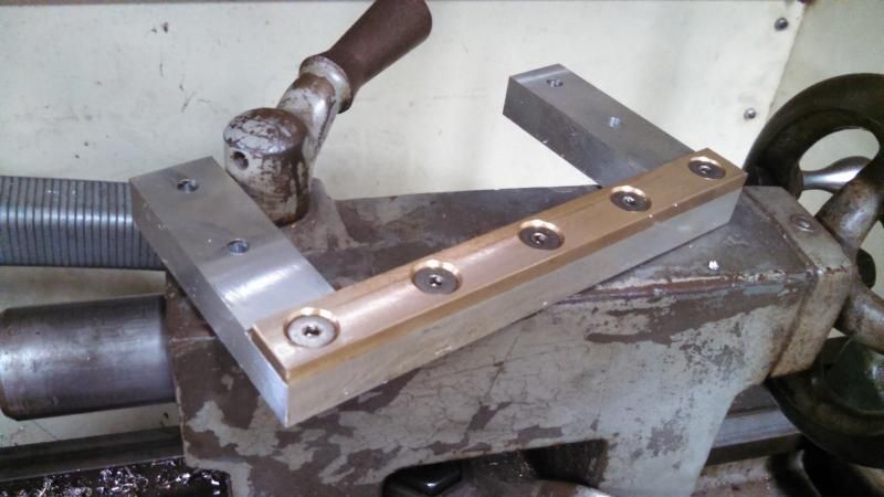
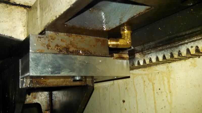
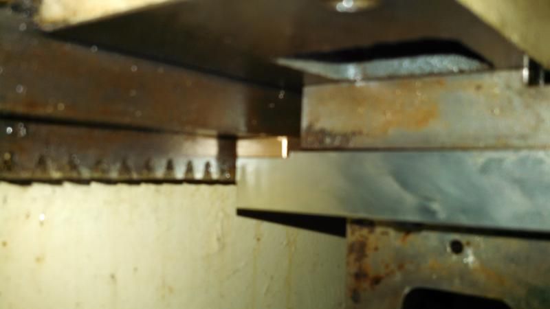
I decided to add a front gib to the lathe. I machined it out of 3/4" 7075 aluminum and attached a strip of 932 bearing bronze to the front edge for the bearing surface. The carriage does seem to have a good bit of drag now, but on the plus side I can no longer lift the front edge at all. I don't have it back together yet, but wanted to post up these pics and see what everyone thinks of both the idea and the execution.

Completed Gib Assembly:


Installed Gib:


Latest posts

Back
Top