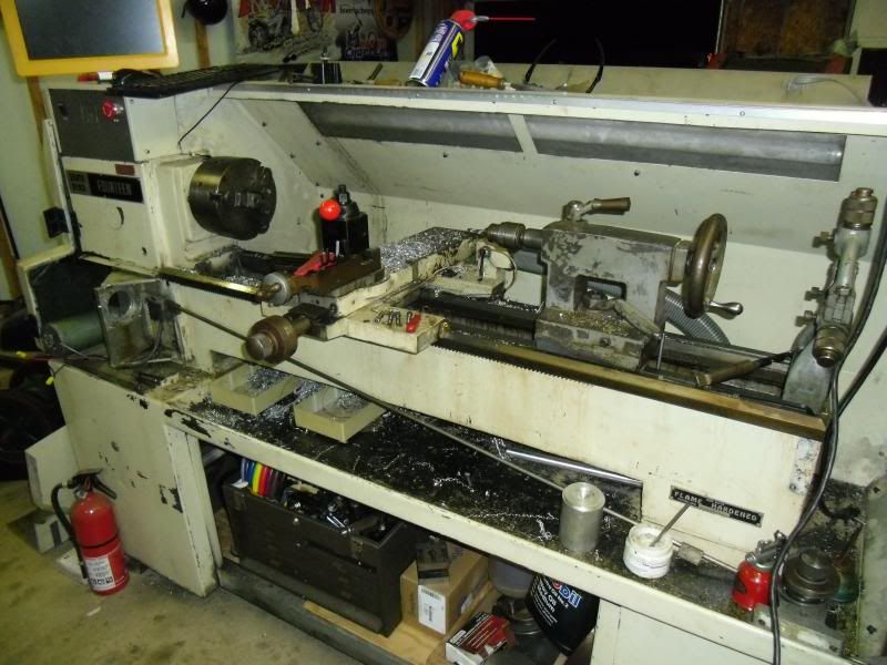
Surface finish issues on CNC conversion

Home Model Engine Machinist Forum

Help Support Home Model Engine Machinist Forum:

This site may earn a commission from merchant affiliate links, including eBay, Amazon, and others.
With such a long component such as a lead screw, the fact that it’s over an inch in diameter doesn't stop it being easily bent. An example would be railway lines which are large in section but flex all over the place.
Noitoen, If a screw was bent it would put force on the saddle every rotation, no matter how fast or slow it was going. As on cnc machines the saddle is always connected to the screw you get a mark the same pitch as the screw.
Is there a way to remove the tailstock end lead screw bearing to expose the end of the screw and remove the spring cover. Run the servo motor and if the screw is straight it should remain straight. If the screw is bent then you will get a circular path drawn by the end of the screw.
 
The gibs are all fine, I went over them this evening. The carriage only has a gib at the rear, because ordinarily the cutting force of the tool would keep the front of the carriage in contact with the bed. The rear gib has little-to-no effect on this because it is the front of the carriage that is lifting. I verified that tonight. I put a mag base and a DTI on the carriage tonight, referencing the flat way on the bed, and ran it manually up and down the ways. I noticed that when I ran the carriage towards the headstock I got a repetitive .0015" jump. Here's where it gets really weird. I also noticed that when I ran the carriage away from the headstock the DTI stayed steady. To prove this wasn't a fluke I put an identical tool in the toolpost that was a LH insert holder and took a pass away from the headstock. No surface variation!

Now I'm thoroughly confused. The front edge of the carriage jumps in time to the leadscrew pitch when travelling towards the headstock, but not when travelling away from the headstock. How can that be? Atleast it seems I can rule out bent leadscrew, but now i'm kind of stumped. My guess is an issue with the leadscrew bearings, although I'm not sure in what manner they could have failed to cause this issue in only one direction.
 
So from your new information, you have a either saddle which is worn or the gibs to re-scrape in or both.

Always remember that a lift of a thous and a half is a error of at least 3 thous -in the round.
 
Always remember that a lift of a thous and a half is a error of at least 3 thous -in the round.

That is quite wrong.
A LIFT makes a much smaller error. The error depends on the diameter and can be calculated by Pytagoras.

Also, there is nothing to be scraped, he explained how his gibs look like. There is none that prevents the saddle from lifting in the front. That is a common construction.

You have to check the axial play of the leadscrew! My guess is, that it is quite large. And my second guess is, that the leadscrew bearing on the TS-side is completely ruined.

Nick
 
It is a bit since I did both Pythagoras and the Euclidian propositions ( 1946) but I cannot recall either party writing about anything other than 2D geometry.

I can, however, recall what a professional owner of a slideways grinder said about my lathe and that the cost of the bed reground and the saddle etc Turcited was £250 which I believe is about two fills of a fuel tank on an average Merc or Audi in Austria.

We are talking about solving relatively inexpensive problems
 
If the radius of the test-piece being cut is 10 mm and the saddle is lifted 0.04 mm, the variation in radius would be:
10 - sqrt(10^2 + 0.04^2) = 0.00008 mm. Or even less considering levers.

It might well be, that the leadscrew pushes/pulls the saddle in X-direction. This could be reduced / eliminated, if the saddle's rear lower guide is precisely adjusted and all ways lubed. That rear lower way is the most neglected on lathes.

I made a similar observation with my Chines scrap lathe. That just came to my mind while writing this.


Nick
 
That still sounds like the lathe bed is twisted a little because the machine isn't level. If you do not have access to a precision level I would try adjusting one of the leveling feet until you see the rocking of the saddle stops. Not the best way to do it but it should show if level is the problem. A simple fix if it works. Level is really important on a lathe. The bed will twist and do just what you are saying if it is not level.
 
Last edited:
I levelled the lathe with a Craftsman digital level. No, it is not a precision machinist's intrument, but it does level to .1 degrees and the lathe is still reading dead 0 across the ways at the headstock, across the ways at the tailstock, and along the flat way.

I would note that the amount of lift might not be directly proportional to the amount of variation in my diameter. The older-style one-vee and one-flat ways on my lathe mean that any lift of the front edge of the saddle (the vee-way) could then also allow some x-axis variation.

The ways and the ballnuts on both screws are all lubed at the same time by a bijur system. Yes, my garage is cold, but it's all still flowing fine. Every motion of the carriage leaves a nice film on the ways of Vactra #2.

Goldstar, could you elaborate on how the fit of the saddle to the bed could wear in such a way to cause this? I'm not sure I can believe that the bed and carriage are worn, however. The bed is hardened, there is not a single wear ridge or line on it anywhere, and the problem exists for the entire length of the bed whereas i'd expect any serious wear to be worse near the headstock.

Thanks for all the input guys. I will figure this out and get the lathe back up and making good parts.
 
Now I'm thoroughly confused. The front edge of the carriage jumps in time to the leadscrew pitch when travelling towards the headstock, but not when travelling away from the headstock. How can that be? Atleast it seems I can rule out bent leadscrew, but now i'm kind of stumped. My guess is an issue with the leadscrew bearings, although I'm not sure in what manner they could have failed to cause this issue in only one direction.

I don't think you can rule out anything on the leadscrew assembly yet. It could be a simple matter of torque keeping the saddle down in the reverse direction and lifting it in the forward direction. That torque could be due to a ballnut issue, bent screw, bad bearing, etc.

I think your best bet is to remove the lead screw and support bearings and have a good look at them, and check the ballnut as well for free movement and excess play. If you do decide to remove the ball nut do it over a clean bucket with a clean rag in the bottom to catch all the balls that will fall out, putting it back together could be very time consuming too.

The other thing you could try - "preload" the ballscrew downwards by just a touch to put a load on the saddle. Adjust the support bearing downward - there is likely enough flex over the majority of travel that say 0.025" misalignment vertical won't harm anything but will help with the saddle lift, or there may be so much flex it doesn't do anything. Worst case is there isn't enough flex at the extremes of travel and it binds the ballnut / support bearings which could cause damage...only you can tell as you have the machine...

Good luck

Mike
 
Imitially, I would forget or put to one side issues such as CNC, leadscrews and whatever and have a look at your lathe bed, naked and unashamed and clean it down of everything that hangs on it- apart from the headstock.
Then I would examine every bit of the saddle- in bits carefully noting where the shims and gibs would go back to.
I would then clean every( EVERY) trace of oilfrom the bed and everytrace of oil from the saddle. I would then blue in the underneath of the saddle with engineers blue and note- where it fits and where it doesn't. You might be advised to make a paper 'map' of both faces. If and it is a big IF that you have an even distribution of rubbed markings on both the lathe bed and the inside of the saddle others are right and I am wrong. If I am right, you have a restoration on your hands. If you are right, you can now do the gibs and see whether your 1.5 thous or whatever is correct and you can blue in your gibs so that you are sure that they fit ( FIT) I'm using capitals and I make no apology for this. If I am wrong and you actually have an all singing,all dancing lathe, you can carefully fit evey thing up and adjust the shims and guides to just remove any show of tightness after a thin( very thin) film of oil is used.

I think that is what I would start at.

I've done several lathes in my years but the last lathe was as I said professionally re-ground on the bed and the under saddle. the drop was built up with turcite but I digress. Some comedian asked how it measured after all this. i simply replied that I had removed the protective oils, re-oiled lightly and the whole lot literally sucked onto the bed.

Once you have done this and are sure that your lathe is OK to operate as a plain lathe- you can move on.

Others may differ- that is their right.

Good Luck

Norman
 
I levelled the lathe with a Craftsman digital level. No, it is not a precision machinist's intrument, but it does level to .1 degrees and the lathe is still reading dead 0 across the ways at the headstock, across the ways at the tailstock, and along the flat way.

Thanks for all the input guys. I will figure this out and get the lathe back up and making good parts.

.1 degree over say 10 inches is going to be off by over 1/64 of an inch. Not close enough. That's enough to let the saddle rock on the bed. I really think your over thinking what is wrong with the lathe. But that could be a good thing with an older machine. Still I'd play with the leveling screws a little to see if the problem goes away.
 
Bret, I'm looking for a good machinist level to either buy or borrow.

Norman, while I agree that your approach would be the most thorough and leave no possibility of contributing factors, the fact remains that 8 weeks ago when I bought this lathe it was making good parts. The previous owner is a friend of mine who has a part-time machine shop. He owned this lathe for a couple years and ran it regularly and never encountered this. I have myself owned and operated several lathes with serious bed wear, .003-.004 or more near the headstock, and while they all cut noticeable tapers on z-axis passes they never made a pattern like this. There's also the fact that loosening up the LS thrust bearing housing makes this go away.

I'm thinking that after removing the leadscrew I'll figure out a way to make some small/light passes with the carriage with nothing attached to it. Perhaps it could even be pushed by hand for a .010" pass on aluminum. If it cuts a good smooth surface without the leadscrew on the lathe then it's got to be associated with the leadscrew.
 
There's also the fact that loosening up the LS thrust bearing housing makes this go away.

So go to your shop and disassemble it. Stop waisting time with looking and pondering at unrelated places.


Nick
 
So go to your shop and disassemble it. Stop waisting time with looking and pondering at unrelated places.


Nick

yes listen to this man. this is a lot of thread for something that appears to be related to leadscrew runout as well as a probable defect in how the carriage mates to the table. the carriage either rocks or the leadscrew is so far out that it actually lifts the cariage off the ways. the machine needs to be atleast partially disassembled and the leadscrew checked for straitness, bearings for runout and the bed needs to be leveled at a minimum. some machines can distort under there own weight if not leveled correctly resulting in corkscrewed ways that will effect the fitment of the carriage. once the ways are level and checked for straitness you may need to remove the carriage to check the contact pattern with blueing.

i've come across MuellerNick's youtube channel recently and it appears he's quite knowledgable of such things.
 
Not withstanding Nick's sound comments, if you can get your thinnest feeler gauge ( say 0.0015?) underneath your saddle- anywhere, you have to examine and correct it.

There is a comment- it may sound offensive- but you have to get used to the idea of regularly removing bits from your lathe for checking, cleaning etc. You might as well get into the habit now.
 
Last edited:
I fully intend to take the lathe apart as-necessary to figure this out. As I mentioned early on, I'm working on a Christmas present right now and I can't take it apart until that's finished. Fortunately I can limp it along until then. Since I'm not taking it apart until then I figured I'd test all the theories that didn't require dis-assembly. It seems I've reached the end of that, and I'm not surprised. In a couple of weeks I'll be able to spend the time necessary to take it apart.

Does anyone have a link to a good guide on bluing the ways and checking them, should it prove necessary?
 
Does anyone have a link to a good guide on bluing the ways and checking them, should it prove necessary?

Here ya go:
[ame="http://www.youtube.com/watch?v=Y8NqeD73ZZ4"]YouTube[/ame]

Hahaha!

Spotting with blue doesn't give you any numbers, so it won't help that much.
Here, in the very beginning, I check a way's straightness with a precision straightedge and a DI (as depth micrometer):
[ame="http://www.youtube.com/watch?v=90KpLbyvlPk"]YouTube[/ame]
If you want to know the ballpark of a bed's wear:
Clamp a DI on your saddle and let it stick out as much as possible to the left. Put the DI's tip on the bed. Crank the saddle to the left (you started at the very right, did you?) and read the deviation. This method is not precise, but it is quick and requires no disassembling.

Maybe you watch my whole channel: My channel (does that link work?)


Nick
 
Last edited:
once the ways are level and checked for straitness you may need to remove the carriage to check the contact pattern with blueing.

i've come across MuellerNick's youtube channel recently and it appears he's quite knowledgable of such things.

jleatherman said:
Does anyone have a link to a good guide on bluing the ways and checking them, should it prove necessary?

Maybe you watch my whole channel: My channel (does that link work?)

that's them! nick i came across the channel by a total coincidence and thought the user name looked strangely familiar. btw great videos on scraping! a skill i have yet to learn.
 
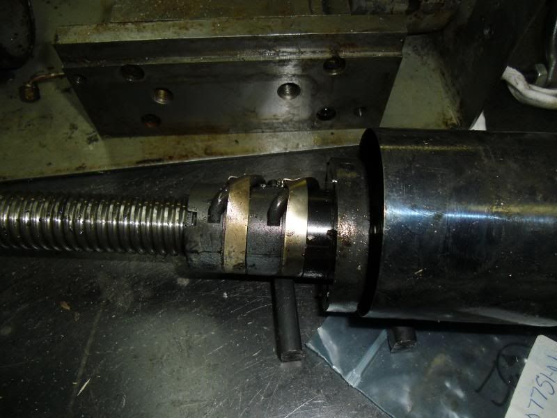
Bringing this back up. I'm finally between projects enough to have the time to disassemble my CNC lathe. I need to make sure the leadscrew isn't bent. It seems more and more likely as I remove parts I find nothing else wrong. So far I've removed the bearing on the TS end of the leadscrew and it's fine. The ballnut also runs smooth, no problems there. Also, without the leadscrew on the lathe the carriage moves without the lifting I noted before with my DTI, so the lathe bed is fine.

The two remaining pieces to check are the leadscrew bearing on the HS end and the leadscrew itself. I've got 2 questions. Based on the picture, is this the kind of ballnut that can be removed without losing all the balls? If not, how can I get it off to check straightness?

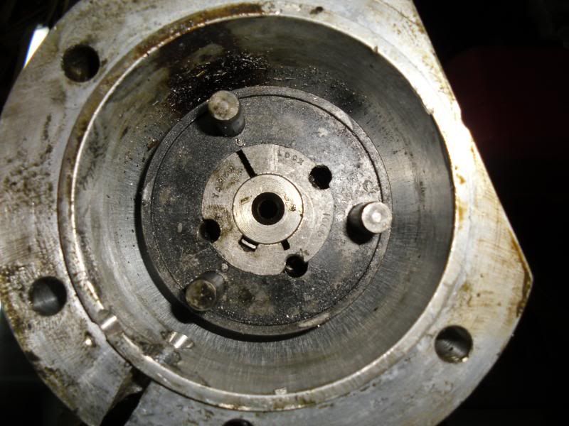
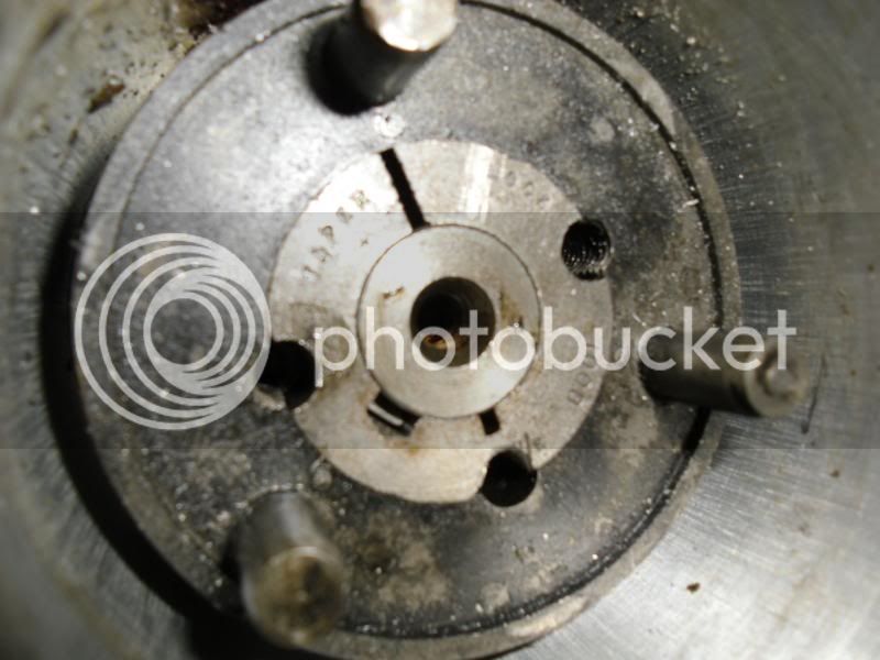
Second question, I can't get the coupler off of the HS end of the leadscrew. I've attached a picture. It seems to be some sort of taper-fit inner piece with a key. I removed two setscrews that were in the holes between the inner- and outer-pieces. I didn't want to just start pulling on it if there was some other locking feature. Anyone familiar with this sort of coupler?


From the photos of your coupler it looks like it is one of the many variations of taper lock. The two opposing setscrews pull the taper to lock it and the third tapped hole between them jacks the taper apart to release it. You remove the two screws, as you have done, and then put one of them in the third hole to release the taper.

Look down the three holes and see if the threads are arranged differently on the middle hole from the other two to be sure.

Gail in NM
 
Back
Top