Split Eccentric

Home Model Engine Machinist Forum

Help Support Home Model Engine Machinist Forum:

This site may earn a commission from merchant affiliate links, including eBay, Amazon, and others.

Captain Jerry

Project of the Month Winner!!!
Project of the Month Winner
Joined
Dec 2, 2008
Messages
971
Reaction score
9
I think my next major project is going to be an engine that was not built in the late 1880's even though it could have been and maybe should have been. Those were great times for steam engines. Lots of visible action. simple mechanical principles, and form was at least as important as function. This will be a two cylinder engine with cylinders on opposite sides of the crankshaft.

I am not ready to post a design model because some of the final design features have not been decided. One of the design features that I have not finalized is the location of the eccentric. There will be no need to reverse the engine so there is only one eccentric per cylinder. The crankshaft will be a built up type with three main bearings. The eccentrics could be outside the crank webs as normal but the engine will be more visibly interesting if they are inside, on each side of the center main bearing. This means that they will have to be installed during crankshaft fabrication or of some split design that can be added later.

A split design makes good mechanical sense, but it will be completely hidden and at this scale (1/4" shaft, 5/8" eccentric disc, .100" throw) I'm not sure I could do it right. I have seen other models with inside eccentrics but I have never seen any of the design details. If anyone has experience with this, or if they know someone who has, or if they have heard of someone who might have, I would appreciate a little input.

Second question. When was the D-valve invented? Is it out of place on an engine of this vintage? Would a piston valve be more appropriate?

Thanks for any comments or opinions.

Jerry
 
Jerry,
Three cylinder Shay engines have center eccentrics for the center cylinder. The early cranks had the eccentrics machined on the crank shaft. Later versions had a split eccentric to simplify the machine work.

Here ia a small marine engine with inside eccentrics.
http://www.gouldstudios.com/me_SteamLaunch.html
I have a copy of the book the images are from and I can answer detail questions if needed.

The inventor of the D slide valve was William Murdock in 1799.

Dan
 
Jerry

My over crank had excentrics inside the crank web. I just made them solid and pinned one of the webs so that the crank could be split, once everything was up and running and proven, I simply pinned the web in a more permanent fasion.

Hope this helps

Stew
 
Sounds like a better approach than a split one - doing that in 'our' sizes could get tricky.
 
sbwhart said:
Jerry

My over crank had excentrics inside the crank web. I just made them solid and pinned one of the webs so that the crank could be split, once everything was up and running and proven, I simply pinned the web in a more permanent fasion.

Hope this helps

Stew

Thats OK Stew until you do what I have done twice once on the 14xx 5 inch gauge loco and I did it again on my triple expansion engine. Made a nice job of the cranks silver soldered up checked up all OK . Then Opps no eccentrics in the middle

so had to make split one , easiest way is to start with rectangular bar stock work out the throw required then get two pieces one to cover the large side and one for the short side, clamp together and fit the clamp set pins . now you have the split line in place ,mark out the centre ,set to run true in four jaw and turn up in the normal way.

note I still put in a grub screw in the thickest part to clamp up


the sizes for my triple where 5/16 thick one bit 1 inch wide and the other 3/8 wide


Stuart

Spending more time making jigs and fitments than working on the projects at the mo
 
hi,
if one of your crankshaft web is circular, you can use it as an eccentric. of course in this case you dont have the choice of the eccentric angle, and AFIK the only compatible valve gear being the Hackworth one.
I did that years ago with a tiny 0 gauge loco, 25 mm between frame for 2 cylinders 8.5 mm bore, no room left for eccentrics!

Zephyrin
 
Jerry,

I had to make a split eccentric for the Stuart triple I'm currently building. The single piece crank is 3/8" diameter, so only a little larger than you are contemplating. The split one really wasn't all that much more difficult than the non-split eccentrics. The key is to draw out a scale diagram to figure out exactly where the pair of cheese head screws are to be located, as you need to drill and install those screws before turning the eccentric profiles. If you mess up your math or drill holes too deep or not deep enough, you will later cut into the screws or their holes. My engine does forward and reverse, so I located one screw in each eccentric, facing opposite directions.

The steps I went through:
  • Cut the blank in half, then clean up the cut faces
  • Crazy glue the two halves back together
  • Face an end and drill the hole for the crankshaft. These become your reference points
  • Drill the tap, clearance and counter bore holes for each of the opposing cheese head screws, then tap the holes. Here is where the careful drawing helps, as you need to be very careful with the depth and location of the holes.
  • Split the halves and clamp them back together with the cheese head screws
  • Machine the eccentrics as normal. If your math was right, all will be perfect

Attached is a photo I took of the two partially machined non-split eccentrics, the unmachined split eccentric bolted together (you can just make out one of the bolt holes, and the reference centre lines for the off centre turning to be done), and the jig I used to turn the off centre eccentrics. I nailed it on first attempt, and these were the first eccentrics I've ever made.

Robin


IMG_8918 - Copy.JPG
 
Thanks for all of the really useful replies. I now have a plan of action. I wanted to make split eccentrics, just because it seems like the right thing, but as Tel said, its risky. So the first part of this project will be a pair of split eccentrics, using the methods shown by Robin and Stuart. Its really not much different than a split eccentric strap or a split big end except that the screws are inside the circle.

If I fail or get disgusted with the results, I have a fall back plan. I can use solid eccentrics and a temporarily pinned shaft ala Stew's method. I may even go ahead and fix the crank webs permanently because there is nothing worse than a wobbly crank and I like to use a single pin through the length of the web to fix both the shaft and the journal. I will use grub screws to adjust the timing and when the angle of advance is worked out in testing, I will file flats on the shaft. Since there is a main bearing between the eccentrics, when the shaft is out of the bearings, the eccentrics can be slid toward the center and the flats filed or milled.

It feel good to have a plan. It will feel better to have parts.

Jerry
 
It has occurred to me to me that with only a single eccentric (given tht you don't need a reverse), you might have difficulty finding room for a second cheese head screw. You might have to use only a single cheese head screw on the fat side. If you used a key rather than a grubscrew to fix the eccentric to the crankshaft (as I have), then one screw might be more than enough to hold the halves together. You most certainly would need at least a second screw while machining the eccetnric, which you would machine away very carefully at the last possible moment.

With the double eccentric, I was able to locate a screw in each of the eccentrics.

Good luck, and all the more reason for the scale drawings.

Robin
 
Jerry,
You could consider slip eccentric which could be made in two pieces. The simplest form is to simply make an extra wide key slot in the eccentric so the key will engage with the slot in the eccentric at the angle of advance for the forward or reverse direction.

It is really only a movable eccentric to get forward or reverse with a single eccentric. Charlie Dockstader did a program for slip eccentric.

Dan
 
It looks like I have plenty of room for two #2-56 SHCS in an eccentric with 5/8" diameter and .100" throw.

Jerry

split eccentric.jpg
 
Boy! That was easy!

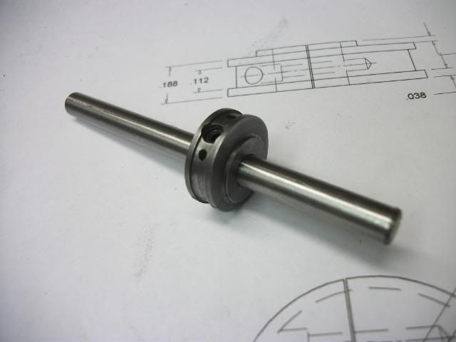
I waste more time worrying about the unknown than doing it and moving ahead. Since I don't have any #2 cheese head screwa I used Socket Head Capscrews and there is just enough room in a 5/8" eccentric. I put the clamp screw heads in the small half and had room for a #8-32 grub screw in the big half. I used a new method, working on the parent bar and not parting off until the final step. The method is new to me but I'm sure I must have seen it on HMEM. That's where I get all my original Ideas.

Now I can move on with the rest of the design.

Jerry
 
How about a split eccentric with NO groove in the ID? Instead, turn the male eccentric (the part on the crankshaft) with a pair of rims. The split rod goes on, and the rims retain the rod. This might be easier than turning a tiny groove in the eccentric rod.
 
Swede - I don't think I follow what you mean. I get the rings/rims securing the halves of the split rod, but if the rims aren't split, how do I get them past the crank webs?

Here is my solution. i think it is different enough that it is worth posting some pics.

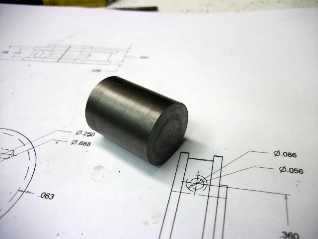
Starts out with a short length of cast iron rod that is .800" dia.

spliteccentric047A.jpg


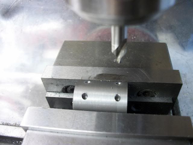
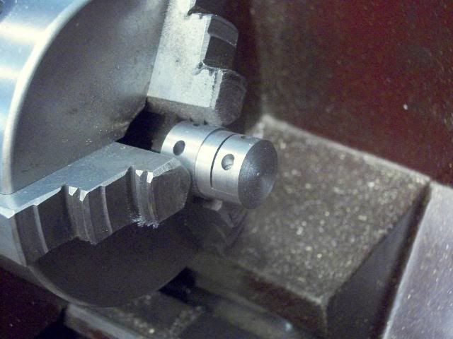
It would have been easier if it was a bit longer but this is what I had. I'm making two eccentrics, one at each end of the bar. The first step is to drill,counter drill and tap for #2-56 screws to clamp the two pieces together after they are split. Holes are .360" apart (.180' either side of center.

spliteccentric048A.jpg


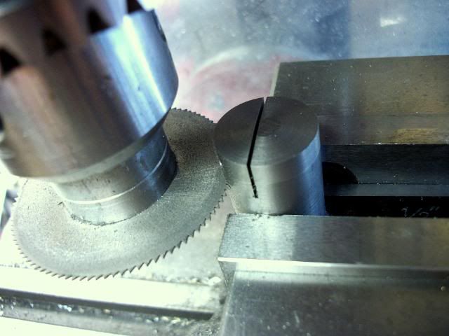
Next is two saw the separation slit at either end of the bar. The position of this slit is critical. I am looking for a .100" throw so the edge of the slit closest to the center must be above the center by one half of that or .050". A careful measurement showed that the bar was actually .798". With the bar horizontal in the vise, The center of the bar is .399" below the top edge and subtracting the .050" means that I bring the bottom face of the saw down to the top of the bar, note the "Z" reading, and lower it an additional .349" after moving the bar out of the way. You can ignore the thickness of the saw blade. The kerf disappears when the pieces are screwed together.

Sorry I didnt get a good pic of this operation but you can see the end slit in the next pic. The bar is set vertically in the vise with the end slit parallel to the "Y" travel. Eyeball parallel is good enough, The slit disappears when the part is parted off. The second cut separates the small side from the bar ad determines the thickness of the finished part. Make it little wider to allow for facing a shoulder.

spliteccentric052A.jpg


spliteccentric053A.jpg


It is important when drilling and tapping, that you provide a thread clearance in the small segment so that it clamps the two pieces together. I did not have cheese head screws so I used slotted, pan head screws with the diameter of the heads reduced. The resulting head is not as tall as a regular cheese head and the slot is not as deep so you must be careful and use a good fitting screw driver blade when clamping down.

In the lathe, the end of the bar is reduced to .790" diameter. It is now round and concentric with a parting line .050" from the center.

spliteccentric058A.jpg


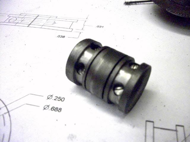
The groove for the strap is reduced with a parting tool to the finished diameter of the eccentric or as close as you can get without hitting the screw heads. I had planned on this being .625" but I had to stop at .645" as I was as close to the screw heads as I dared to go. No big deal. The eccentric strap will be modified to fit. I didn't get a pic of this still in the lathe but here it is after cutting grooves at both ends.

spliteccentric060A.jpg


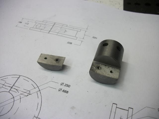
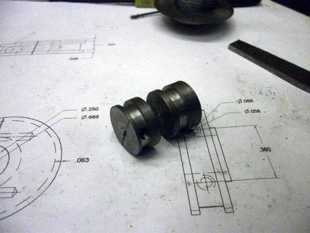
And here they are after parting off. Actually, after parting off the first piece, the bar was faced to thickness for the second part.

spliteccentric063A.jpg


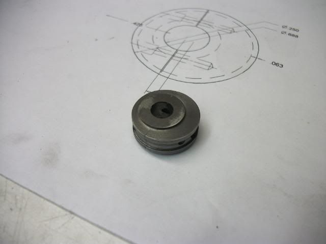
Now the the the part is returned to the mill for drilling and reaming the shaft hole. Set up in the vise with the slit parallel to the vise jaws so that the vise aids the clamp screws. The part is carefully centered under the quill and then offset .050" towards the split. That should put the point of a spotting drill exactly on the parting line. Drill undersize, ream to size (or .001" under if you have one)X. Sorry, again no pic of this operation. I got swept up in the process. After this, I put it back in the lathe to clean up the faces and turn a shoulder on one face to mate with the center and your mother's brother is named Robert.

spliteccentric046A.jpg

spliteccentric042A.jpg


Almost forgot, drilled and tapped #8-32 through the thick side for a grub screw, being careful to center the hole between the clamp screws.

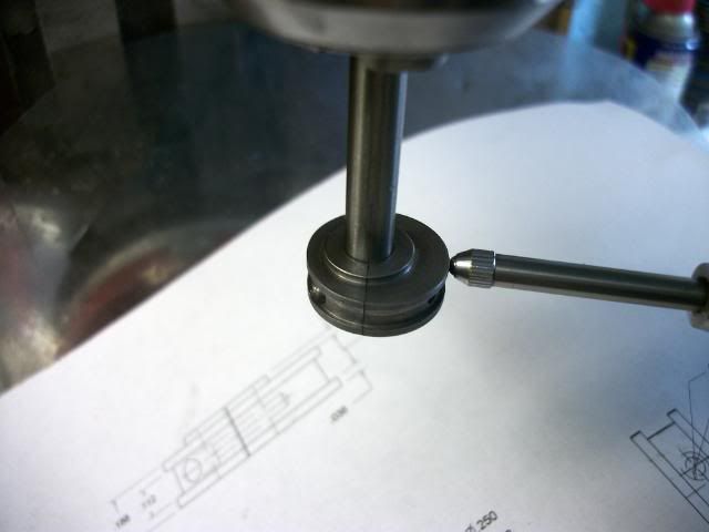
I decided to verify the eccentric throw with a dial indicator.

spliteccentric041A.jpg


It clocks to .102". Crap! I guess I'll do it over.

I hope this made sense. If not, the floor is opened for questions or comments.

Jerry


PS:

My wife was looking over my shoulder when I was posting the last picture and said, "Isn't that a little off center?"


Dan Rowe said:
Jerry,
Three cylinder Shay engines have center eccentrics for the center cylinder. The early cranks had the eccentrics machined on the crank shaft. Later versions had a split eccentric to simplify the machine work.

Here ia a small marine engine with inside eccentrics.
http://www.gouldstudios.com/me_SteamLaunch.html
I have a copy of the book the images are from and I can answer detail questions if needed.

The inventor of the D slide valve was William Murdock in 1799.
558
Dan

Dan, I didn't ignore your earlier reply, I just missed it for some reason. Thanks for the info on the Shay engine and on the date of the D-valve. I haven't decided whether to use a spool valve or a D valve yet, or maybe I have now that I have eccentrics with a .100" throw, that might be a little too small for a spool valve.

Thanks for your interest and your input.

Jerry
 
My wife was looking over my shoulder when I was posting the last picture and said, "Isn't that a little off center?"

Damn! Now you'll have to do it all again! Rof}
 
Captain Jerry said:
PS:

My wife was looking over my shoulder when I was posting the last picture and said, "Isn't that a little off center?"

To which I'm sure your proper response was

*ahem* "yes dear"
Rof}

BC1
Jim
 
Jim

What I said was, "Good eye, Babe." They love compliments!

Jerry
 
Aoooh! You are a silver tongued one aren't you. :big:

BC1
Jim
 
Captain Jerry said:
Jim

What I said was, "Good eye, Babe." They love compliments!

Jerry

Jerry: I have to start paying attention when I read... at a quick glance I thought I saw
"Good BYE, Babe"....

Was thinking that this might cause some delay in future posts from you! :big: :big:

Cheers, Joe

 
Back
Top