Speedys inline twin

Home Model Engine Machinist Forum

Help Support Home Model Engine Machinist Forum:

This site may earn a commission from merchant affiliate links, including eBay, Amazon, and others.

Speedy

Senior Member
Joined
May 3, 2008
Messages
481
Reaction score
17
I am building jerry james hex two.
currently as I am building it I am noting areas that I would like to see improvements on, right after this engine breathes life I will jump right back in to build my version of this engine.

I also plan on documenting my second build on video

sorry I am not taking you all on for the ride, first engine and its sometimes a handful, dont want to complicate things with a camera in the way, expecially when I am using the bigger tools like the bridgeport and harrison lathe.

I am very happy with the progress and my ability to make these parts, took me years of watching all you before I decided to jump in. amazing myself every day!

now just to clarify, the cox cylinder assembly, piston, carburator and plug boot have been purchased
for all your cox needs you really should check out these guys! very kind family run business.

http://coxengines.ca/

Toronto-20120901-00114.jpg
 
This sounds iteresting Michael. I am not familiar with this engine, but will be looking forward to seeing your progress.
 
cranks are getting done.
just need to drill the passages for air and the crank pins.

[ame]http://youtu.be/oiPapnPfHOs[/ame]
 
guys I have abit of trouble.

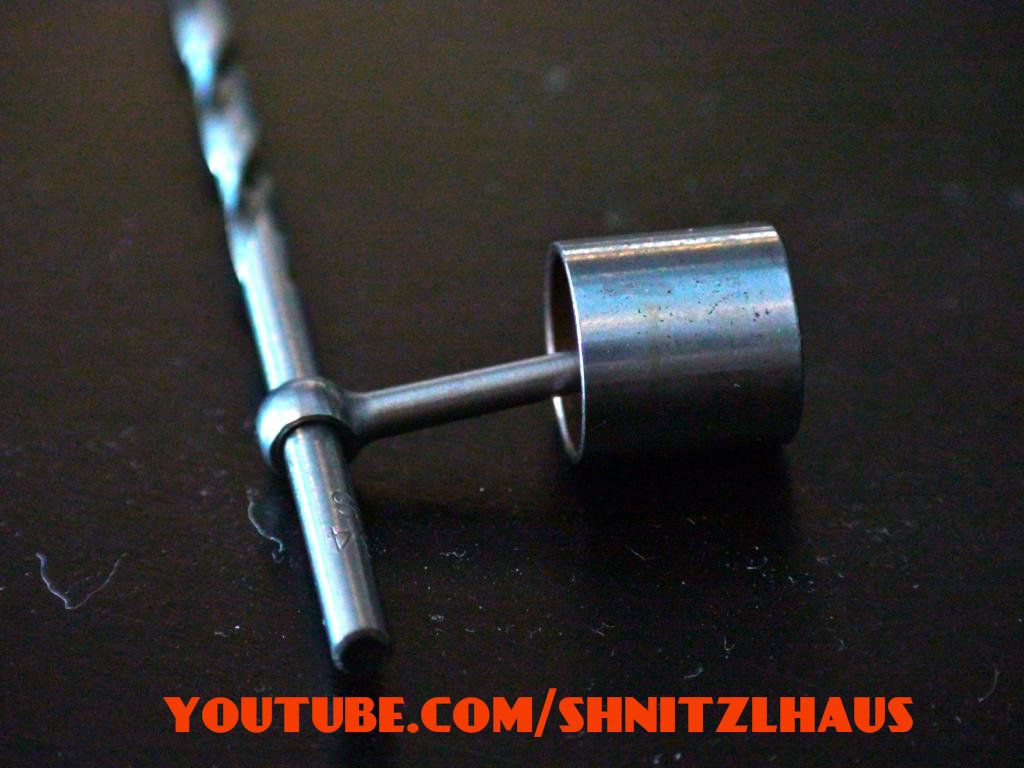
the author of the plans calls for a 3/32 crank pin on the crank shaft but a 7/64 fits my pistons connecting rod way better. 3/32 has allot of side play.
do I go along with what he calls for or do I use the better fit 7/64 :(.

im wondering if he chose the 3/32 to have abit of leeway if the measurements are off the piston will still work? but that logic sounds off as the connecting rod and crank shaft would be worn in short order.
 
I have some old Cox engines and none of them have slop between the rod and crankshaft pin.
 
im thinking the same, why should excessive slop be present.
I will see the procedure thru with the better fitting 7/64 and take it as a learning experience if something proves down the line it should have been different.
 
I think your plan is best Michael. I don't see anything good coming from leaving a lot of play in the big end bearing.
 
Michael,
I miked one of my crankshafts and it came up 0.1065. 7/64 should be 0.1094.
Theoretically, the piston rod shouldn't fit on the 7/64 rod.

Steve Fox
 
Mike,

Looks like you are having a lot of fun with this build. While I haven't flown any 1/2A glow in a while, I will definitely be following along on your progress.

Thayer
 
thanks for the comments guys!

Brian, exactly what I was thinking, at this point I am happy I went with the nicer fit.

Steve, after reading that I ran downstairs to the shop to double check thinking I may have grabbed another drill.
all checks out fine, I tried all 4 connecting rods and all slide on fine, whew close one :) I am going to buy some fresh 7/64 bits to make the pins hope new ones check out just the same.

Thayer, this one is slated to be put into a custom oval midget car or something similar. I am going to build the frame out of small tube and machine my own axles. I am just getting into flying and doubt I could pilot a 1/2A yet as cool as they are.

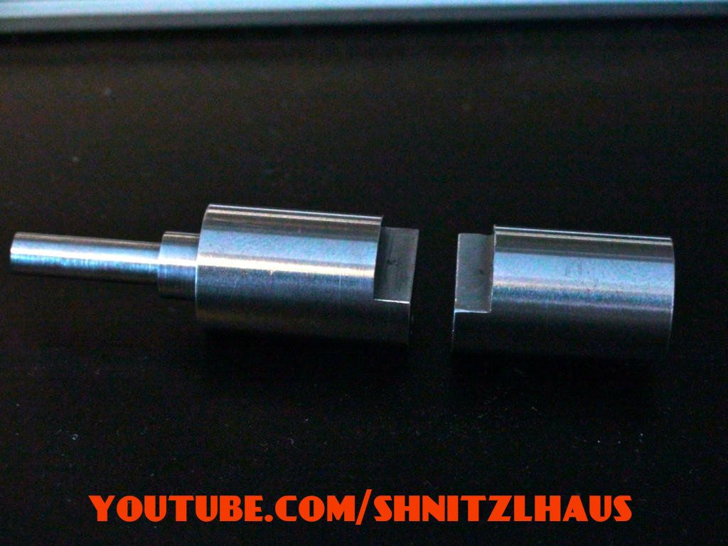
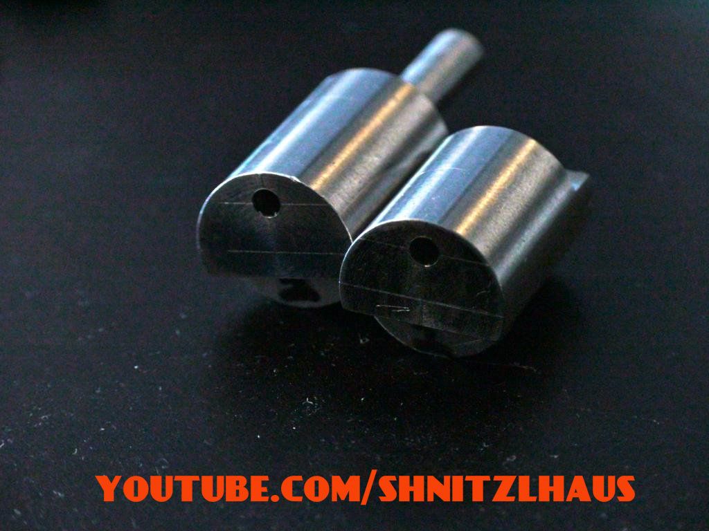
anyhow here are some pictures, all that is left to do is machine the air/fuel mixture timing ports! eeek another but last big step on the crank.

- left to do is ream out the block
- tap the backplate and block
- piston clearance on the back plate
- 6 bolt circle on the back plate
- 1/4-32 unef a2 tap for my carburetor (out of all taps why that one haha)

pictures of the crank at this point.

DSC00387.jpg


DSC00388.jpg


DSC00389.jpg
 
I didn't know you were using a 7/64 drill bit. That explains the difference.
I measured one of mine and it was 0.1075. The flutes are slightly wider than the shank.

I guess every brand is a little different. You may want to take a piston with you when you buy the drill bits.
 
I should have mentioned.

do you think other then being more difficult to work with should I go with anything special for the finnish on the drill bit?
cobalt? titanium? or regular HSS drill bit.

I am stumped again, but I dont think I could properly explain what is stopping me.. but I will try.
in the plans the author tells me to machine the transfer ports I need to put the crank in the fixture and measure .450 from one side of the fixture to the crank pin (this should give the timing as it angles the crank about 18deg) anyhow I varied on the material for the crank fixture he asked to use 7/8 aluminum hex I used something smaller. so will my thinner side walls skew the port timing? I am going with yes but not sure.

** edit, I assume I could just compensate for the measurement by adding the difference of the small part to the large on on the .450 .... example if I had an extra .050 I should have had on my holding fixture I just add that to the .450 and call it .500? sound logic?
 
in the plans the author tells me to machine the transfer ports I need to put the crank in the fixture and measure .450 from one side of the fixture to the crank pin (this should give the timing as it angles the crank about 18deg) anyhow I varied on the material for the crank fixture he asked to use 7/8 aluminum hex I used something smaller. so will my thinner side walls skew the port timing? I am going with yes but not sure.

For the drill bit, on the coated ones I have, the coating doesn't go all the way up the shank, so it won't matter which type you use. Just make sure it is from the smooth part of the shank, not the part that has the info stamped in it. That part will wear the inside of the piston rod.

If I understand correctly, for the measurement, if it were me, I would subtract the difference in thickness from your fixture to the dimension the author said to use. The other option would be to make a degree wheel and figure the opening based on the actual position of the crank in degrees, if he gives that information.
 
could you give me an example of that? seems I would still be in trouble doing it that way.
 
Say the author said use 7/8" and the dimension is .450.
Say you used 3/4". The difference would be 1/2 x (7/8 - 3/4) = 1/16 or .5 x (.875-.75) = .0625.

Take the .450 and subtract the .0625 and you get .3875.
That would put the crank pin in the same location relative to the thinner fixture. If your dimension is not 3/4" then substitute the actual dimension.
It is just half the difference between the proposed and actual fixtures.

I hope I didn't make it harder than it really is.
 
gotcha! sometimes I just need to give it a good thinking :p and a coffee break.
 
I think your plan is best Michael. I don't see anything good coming from leaving a lot of play in the big end bearing.

Hi Brian,

I agree with you.

From my 32 years industrial experience with Ingersoll-Rand T-30 Air Compressors.

Gudgeon Pins must be push fit into piston.No slops
Con-Rod big end on to crankpin.Sliding fit. No slops.

If you can feel a slop,engine or compressor will knock and soon a loud knock and crash comes in days/weeks.

I am now building a 0.46 Glow Plug engine. About to cut the piston and con rod.Now looking for 3/16 reamers to fit gudgeon pin and crank pin.May DIY
"D" reamer .

Will be using Silver Steel as per print. Silver steel is prescribed by the designer.

IMG_0599.jpg


IMG_0567.jpg
 
oops, well I know the feeling now.

everything was going smooth, all the intake slots cut fine and seemed to be dead on where they were suppose be as far as I could tell.
author called for 1/8th transfer ports to move the fuel mixture to the cylinders so I had to drill a hole to connect to the transfer slots, left the measurements up to the user so I took about 45 minutes to think it over.
set up my part and went to town, everything working well then of course the drill bit as it enters the transfer slot grabs hard moving the part in the vise and bent the drill bit hard (surprised it didnt snap with all that flex) their is a boo boo on the part pushed the metal out creating a bulge at the end of the transfer slot :( I hammered it back in. in frustration I was going to just toss the part and call it a day but I decided to continue and finnish the last transfer port on the other end.

since its just a port to move air I am hoping it will still work, the hole is enlarged and oval so it might just get more fuel mixture then the other cylinder.
going to keep it until I know the engine wont run.
 
guys I finnished all the parts, all is left to do is tap for the cylinder and carb.

could anyone tell me the difference between a plug tap and a spiral point plug tap
I need to buy a 1/4-32 unef and the seller is asking me which I need.
 
A standard plug tap has the teeth, actually the grooves between the teeth, in a straight line. A spiral plug tap has the grooves in a spiral pattern.
For what you are doing it won't matter, get the cheapest.
 

Latest posts

Back
Top