You are using an out of date browser. It may not display this or other websites correctly.
You should upgrade or use an alternative browser.
You should upgrade or use an alternative browser.
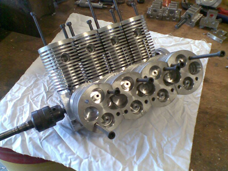
Small model V8 motor built at home scratch built
- Thread starter dixon
- Start date

Help Support Home Model Engine Machinist Forum:
This site may earn a commission from merchant affiliate
links, including eBay, Amazon, and others.
great project! Keep us posted on the progress.
You picked a helluva project for your first build - impressive.
Can't wait to see more.
Ken
Can't wait to see more.
Ken

$190.00
$254.99
Genmitsu CNC 3018-PRO Router Kit GRBL Control 3 Axis Plastic Acrylic PCB PVC Wood Carving Milling Engraving Machine, XYZ Working Area 300x180x45mm
SainSmart Official

$188.98
TM NEXDYNAMI RE41157 Water Pump Compatible With/Replacement For/John Deere 6200 7400 6300 6600 6500 6400 7220 7600 7200 RE41157
VIVID MARKET CORPORATION

$94.99
$109.99
AHS Woodmaster 4400 Maintenance Kit for Outdoor Wood Boiler Treatment
Alternative Heating & Supplies

$403.09
DM14 Engine Build Kit, Metal Engine Build Model Great Metal Material for Engineer for Factory
Easoger Official

$39.99
$49.99
Sunnytech Low Temperature Stirling Engine Motor Steam Heat Education Model Toy Kit For mechanical skills (LT001)
stirlingtechonline

$15.99 ($0.05 / Count)
$18.99 ($0.06 / Count)
HongWay 300pcs 2 Inches Sanding Discs Pad Kit for Drill Sanding Grinder Rotary Tools with Backer Plate Shank and Soft Foam Buffering Pad, Sandpapers Includes 60-3000 Grit
HongWay US

$104.99
Sunnytech Hot Air Stirling Engine Motor Steam Heat Education Model Toy Kit M16-CF
stirlingtechonline

$156.90 ($1.40 / oz)
Replacement Combustion Chamber Kit, Burnham V8 and V8H, 1-6 Sec, 108136-01, 1129
Lynn Manufacturing

$649.00
$699.00
FoxAlien Masuter Pro CNC Router Machine, Upgraded 3-Axis Engraving All-Metal Milling Machine for Wood Acrylic MDF Nylon Carving Cutting
FoxAlien Official

$59.99
Sunnytech Hot Air Stirling Engine Motor Model Educational Toy Electricity Generator Colorful LED (SC001)
stirlingtechonline

$28.51
$45.00
Key Contemporary Buildings: Plans, Sections and Elevations (Key Architecture Series)
Lions Den Books321

$99.99
$109.99
AmTech300 - Boiler Treatment Professional Strength (Rust Inhibitor For Outdoor Wood Boilers)
Alternative Heating & Supplies

$45.99
Sunnytech Mini Hot Air Stirling Engine Motor Model Educational Toy Kits Electricity HA001
stirlingtechonline
Would love to see more pictures.
Mosey
Well-Known Member
Wow! I love the sound.
Harold Lee
Well-Known Member
- Joined
- Apr 23, 2008
- Messages
- 236
- Reaction score
- 2
WOW!!! When I think of a first project I think of a small wobbler or a single steam engine. BUT an eight cylinder internal combustion engine? WOW!!!
That is incredible and you have my admiration.... Wish we had seen the build...
Keep up the good work.
Harold
That is incredible and you have my admiration.... Wish we had seen the build...
Keep up the good work.
Harold
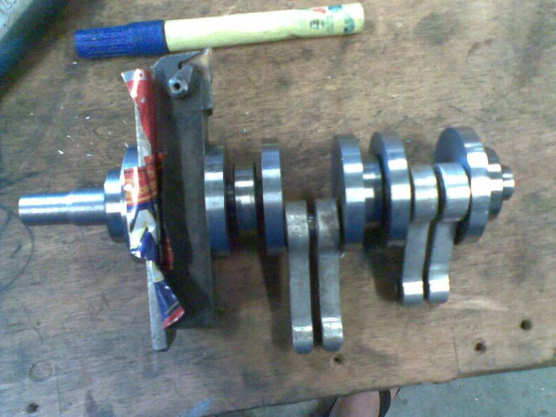
ok my daughter has done all the computer stuff the digital readout on my little lathe is enough for me i am just learning how to text we will see how we go with this the firing order of this little engine is 12478356 number one is left hand side front number two is right hand side front so 1357 on the left and 2468 on the right . notice full stop. im learning. the firing order could have been a few different ways including 12345678 but i thought i had better spread it around as much as i could. the bore is 1.250 and the stroke is 1.187 .the stroke ended up that size because that was as close to the bore size i could get by putting the jaws in the three jaw in the wrong order . because i had to copy these sizes numerous times. the crank has ball bearing mains 15 mm id x 5 and big ends are needle rollers 12 mm id 90 degrees apart starting from front of crank , not like a couple of other throws that i have seen ... but this isnt where it all began, maybe this can be chapter one ...time here is 7.30 pm aest
aust time
aust time
dixon said:http://www.youtube.com/watch?v=ZlCWbpqTXS8
here is my video
i have a lot more photos step by step progress if anyone is interested
what would make you think we would be interested in step by step pictures........
we are not really interested, WE LOVE THEM!!!!
post them up so we all can drool over them :bow: :bow: :bow:
pascal
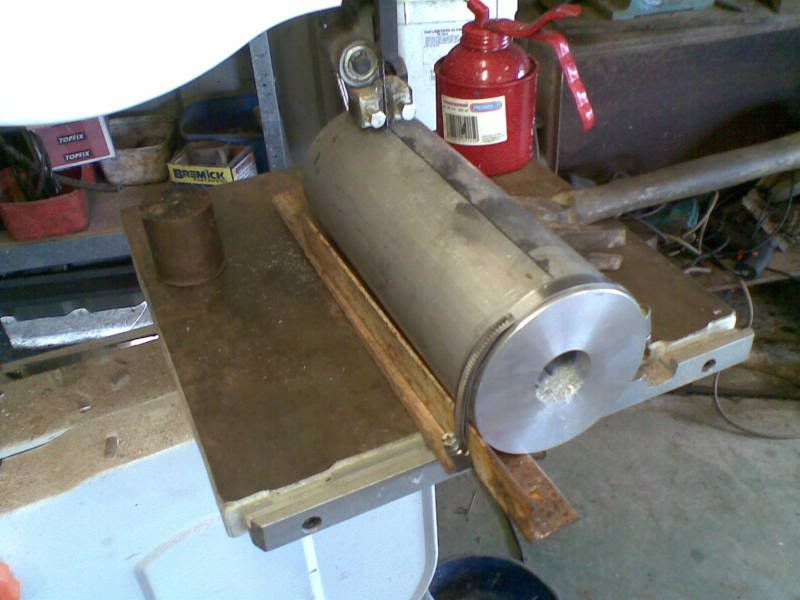
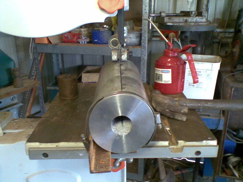
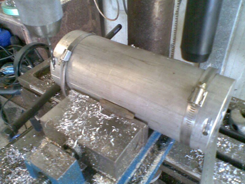
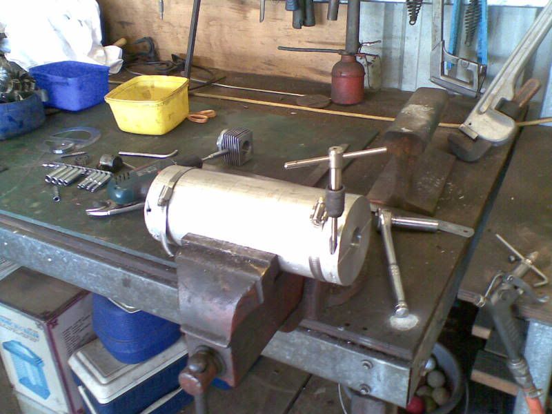
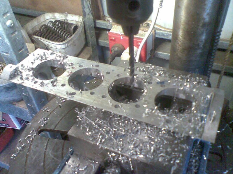
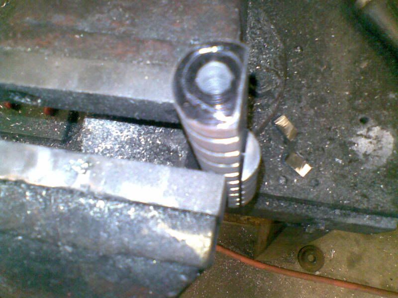
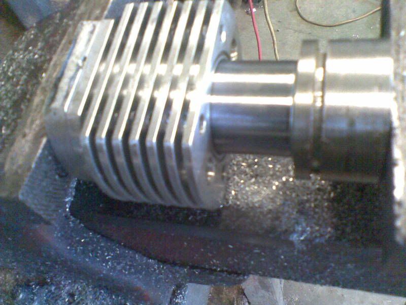
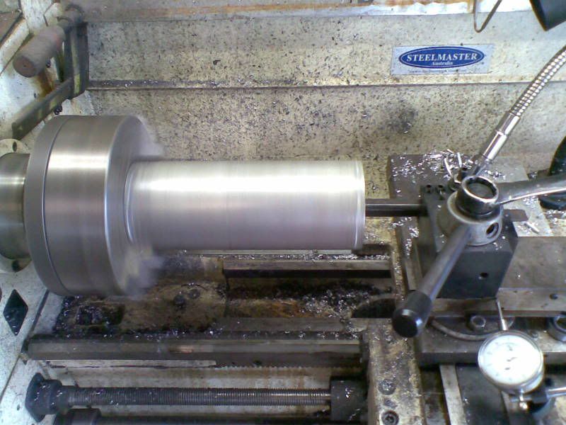
this is the piece of ally i started with. i bored a hole through it ,cut it in half length ways, put two hose clamps around it so i could grab it in the chuck to put two steady tracks on it . then i drilled and taped 4 m6 holes so i could bolt it together and remove the clamps . then i machined all the main bearing diameters and spaces for the crank counterweights. lots more to come


