Small Engine Dyno

Home Model Engine Machinist Forum

Help Support Home Model Engine Machinist Forum:

This site may earn a commission from merchant affiliate links, including eBay, Amazon, and others.

IronHorse

Project of the Month Winner!!!
Project of the Month Winner
Joined
Mar 3, 2008
Messages
243
Reaction score
20
I found some interesting plans and software from Jon Bondy here: http://www.jonbondy.com/software.htm
These are plans and software to measure a small engines RPM and Power. It is a simple system that can calculate the power by measuring the time it takes to recover from a near stall using the MOI ( Moment of Inertia ) of the flywheel. For simple solid flywheels it has a built in calculator. For wheels with spokes and cutouts you need to figure this MOI out yourself. I will model the flywheel in Pro/Engineer and that will give me an accurate MOI.

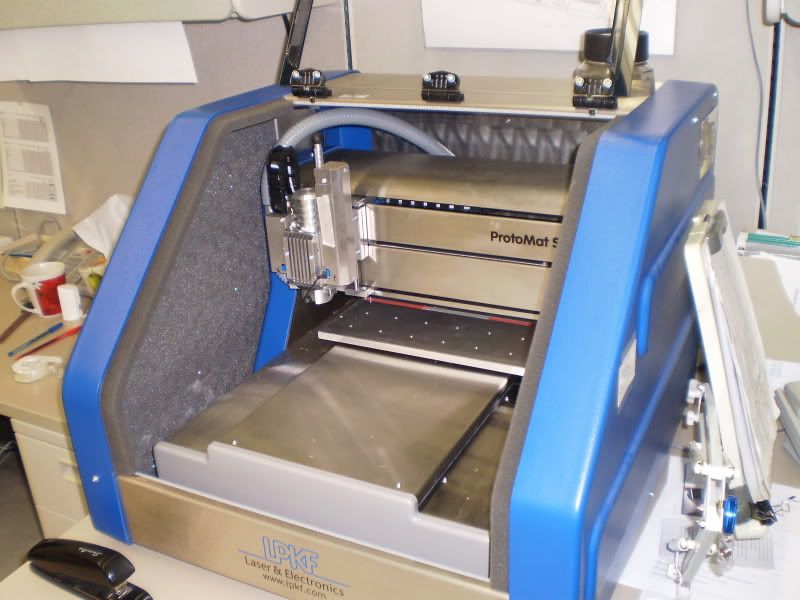
First was to make the PCB. Since I had a Printed Circuit Board Prototype machine at work this was easy. This machine is essentially a 2.5D CNC machine. I can put in sheets of copper clad material, and it will mill out insulating areas around the conductors.

Here is the $27,000 CNC Machine
PhotoMat.jpg


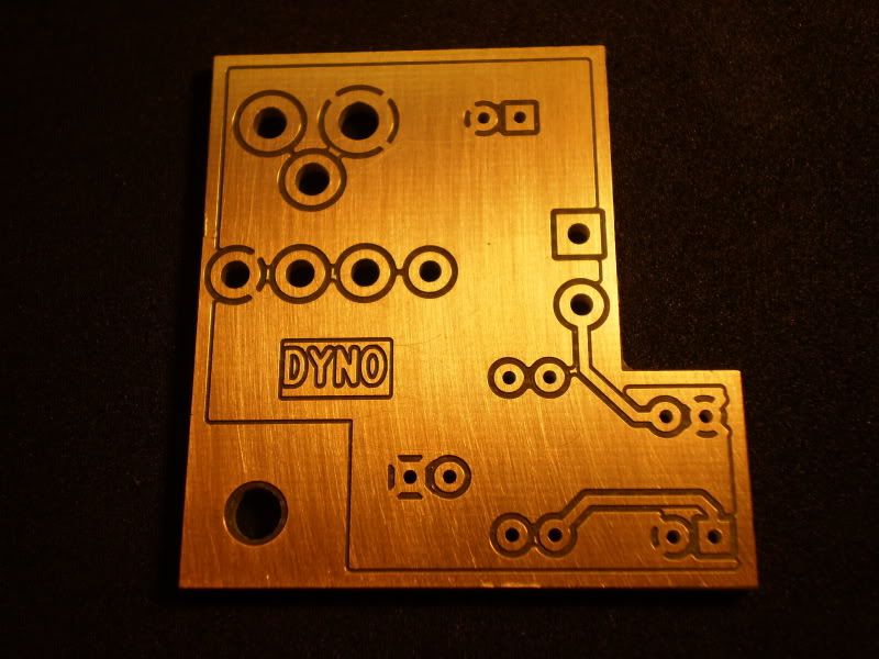
And after 10 Min...... A finished PCB. You can see how the cutter insulated the conductors.
PCBBot.jpg


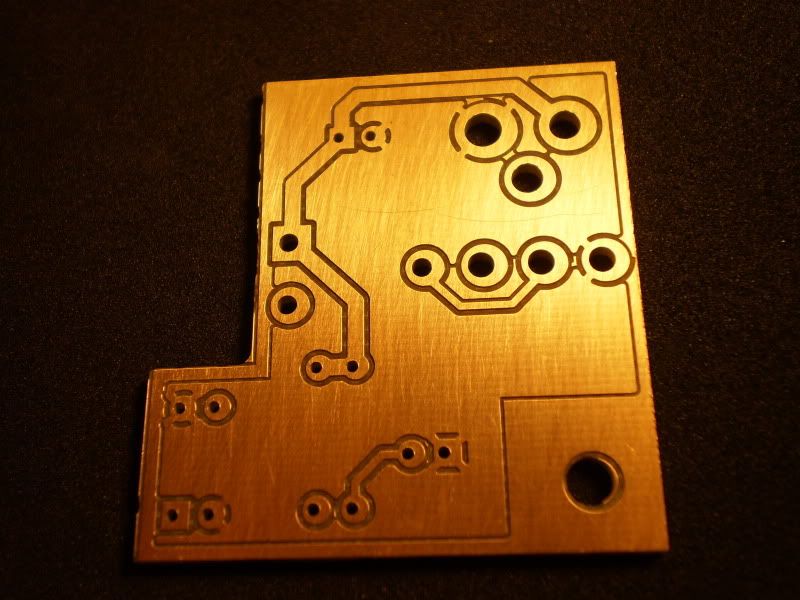
Here is the bottom side. The pads with spokes are Negative (GND) connections
PCBTop.jpg


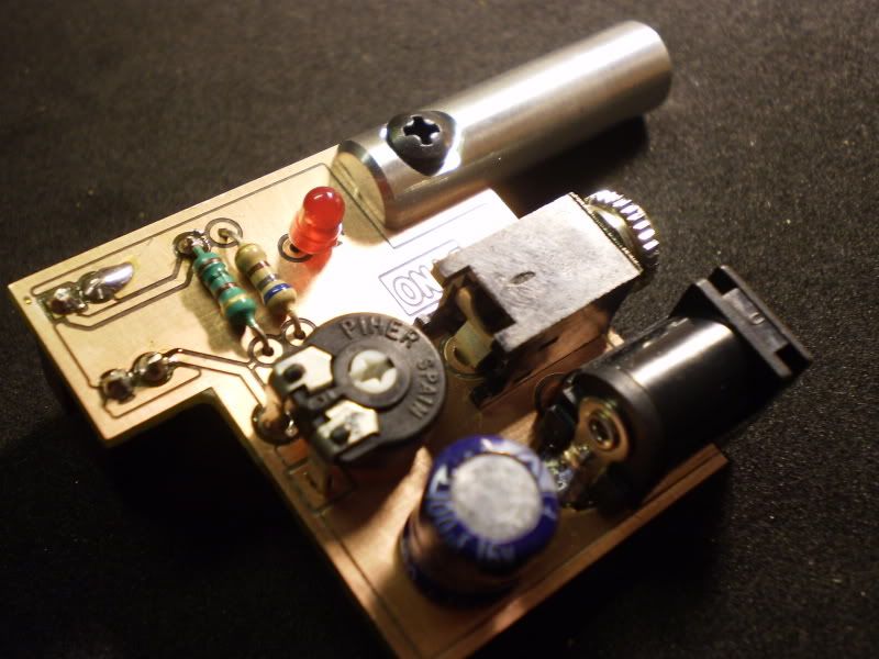
After assembly:
Assembly.jpg


For testing I hooked up my PM-2a Steam Engine:
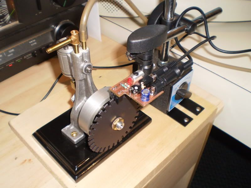
Testing.jpg


Screen shot showing output of one of the tests:
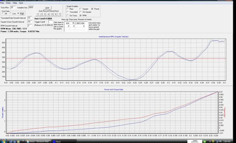
ScrnShot.jpg


Overall it was a fun project, but I am not sure how accurate it is. I will do some more tests on some of my other engines. I think there is a newer program out there that uses a computer mouse's scroll wheel for input.

Well its starting to get warm finally and I think this will be my last Milling/Lathing project until the fall. As soon as it gets hot, I am outside most of the time. Summer is too short in Canada!

But I will still be working on/Cruising in this:
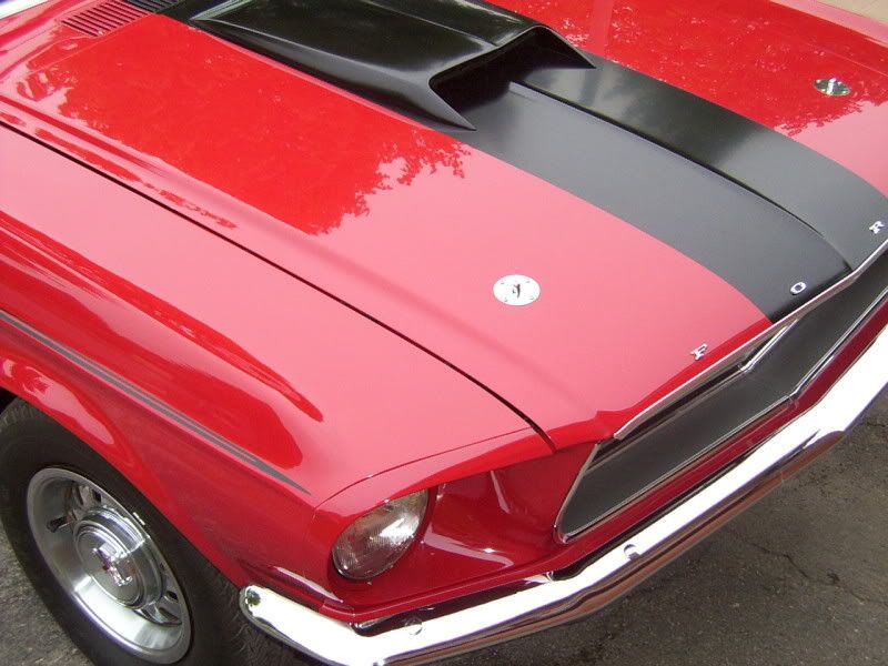
DCP_1313.jpg


Iron Horse


What a cool project !!! I too have built that same steam engine (PM Research's #2A)

Mike
 
How the heck are you planning to stall the Mustang so you can give it a dyno run?

:big:

BW
 
Ha!!! That could get tricky. Last year at a car show, they had a dyno setup, but I was too chicken to let some pimple faced kid rev the heck out of it!

I did do a computer simulation and it outputted HP@325


wow thats a cool Dyno!
where in toronto are you?
I want one :D :D
let use know if you do anymore test's or find another program.
 
hi all

did u find the board schematic, I've looked everywere and couldn't find it...

I would like to build one myself.

BTW great job on yours
 
To get the circuit diagram, download and install the software, start the program and click the help button


IronHorse
 
Beautiful mustang ironhorse, have you had any new updates for your dyno.


I did not have too much luck with this circuit. The readings seamed to be all over the place, I could not get consistant results.


IronHorse
 
I did not have too much luck with this circuit. The readings seamed to be all over the place, I could not get consistant results.


IronHorse
can you email me thge drawing I cant install the program in my office computer
I'm using win 7 64bits pro and it's not compatible

as for reading all over the place, your using an opto coupler and the light flashing at 60 hz can ruine them
try closing the light or covering your motor when doing the test
 
Meh. what about the inertia of the other parts. to do it correctly you have to pull against a brake or calibrate the inertia results by doing several runs with different flywheels or the estimated horsepower will always be low. some argue inertia based testing is better because brakes don't account for the actual ability to accelerate but inertia testing isn't real world acceleration rates in the application either.

the truth is a brake isn't hard to build and the math is easier. a few things that work really well are water brakes which are essentially centrifugal pumps and the dampening is controlled by the water volume or flow rate to the inlet. more water is more load then torque is measured from how hard the engine wants to torque the body of the pump basically the body can be supported by the shaft and an arm mounted to it that pulls on a scale or spring then an encoder or potentiometer can read the movement. or you can get fancy with an eddy current brake which would be a copper or aluminum wheel with strong magnets or electromagnets near it which will generate heat in the wheel. though I guess you could take a permanent magnet electric motor and shunt the leads with a transistor and control rpm by adjusting the current through the transistor....

hey do you think there is a market for such a thing? I think I could do this with an arduino micro controller.
 
I've actually done a lot of small (26 cc) engine development on an inertial dyno. We've tested engines since 2003, initially with the intention of being the first gasoline powered, radio controlled boat to exceed 100 mph. We were successful and still hold the record of 109+ mph set in 2004. For many applications, Including ours, the acceleration performance is by far the most important. This would also apply to most racing applications. Racing engines never run at constant rpm like in ship or aircraft applications.

An inertial dyno is by far the easiest type of dyno to build. I've built an eddy current brake like this one as well. It was much more difficult. The tests on an inertial dyno give you a full wide open throttle curve in a matter of seconds. It's possible to run over 50 tests in an afternoon. That minimizes wear on expensive engines while testing a lot of variables. You can't do wear or endurance testing, but for most other testing, it's superior. See the article on our development of a CMB 35 for an example of what you can do. The construction of our dyno is described in Model Engine Builder. A great article on the different types of small engine dynos is How to Measure Model Engine Performance (use the search function for the title).

Lohring Miller

P1010006.jpg
 
hi are plans availlable for this somwehere
nice setup

The article on our dyno is in Model Engine Builder issue 15. Details depend on the size of engine you plan to test. Flywheel design is addressed here and here. Flywheel strength is very important as is the balance. Machinery's Handbook has formulas for calculating the stresses in a flywheel. We made ours out of heat treated 4140 to be safe, though cold rolled steel has been used by many others.

Lohring Miller
 
Back
Top