This post describes a tool "Simple File Guide" which I built a few years ago and which may interest folks who, like me, have a lathe but don't have a milling machine. It supports the use of common or garden files under muscle power to make flats on round sections or cylindrical segments on flat sections with significantly better precision than can readily be achieved otherwise. In conjunction with a dividing head or a simple indexer based on use of the lathe gear train, the File Guide can help you to make good looking and sufficiently accurate polygon sections e.g. square or hex or matched flats on opposite sides of a shaft.
The process makes use of the lathe, without power, to position and hold the work piece while the File Guide limits the motion of the file to ensure that only the desired excess metal gets removed. Depending on the application, the File Guide may be held in the Tool Post and the work piece in the chuck or the File Guide may be held in the chuck and the work piece in a machine vice mounted on the carriage.
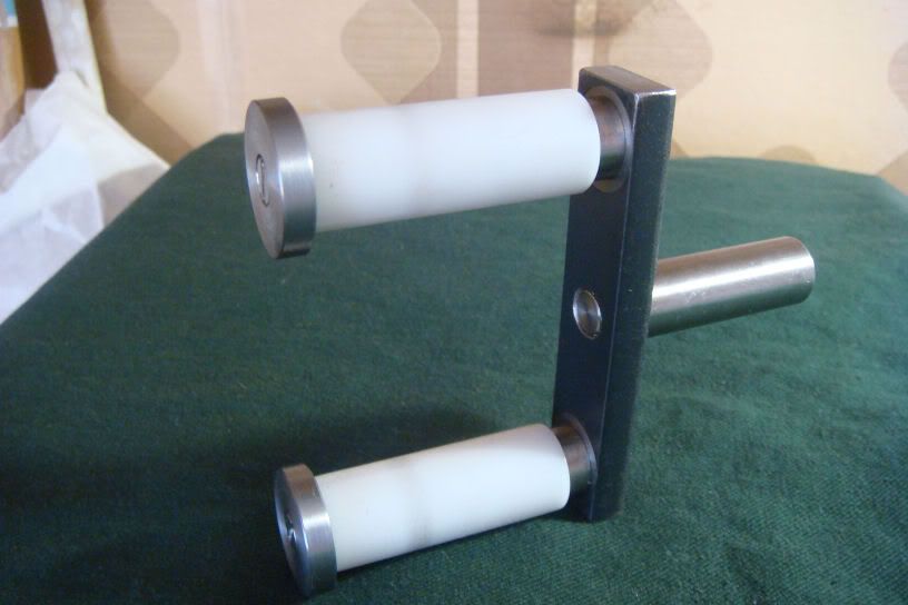
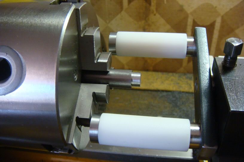
The picture below shows the tool.
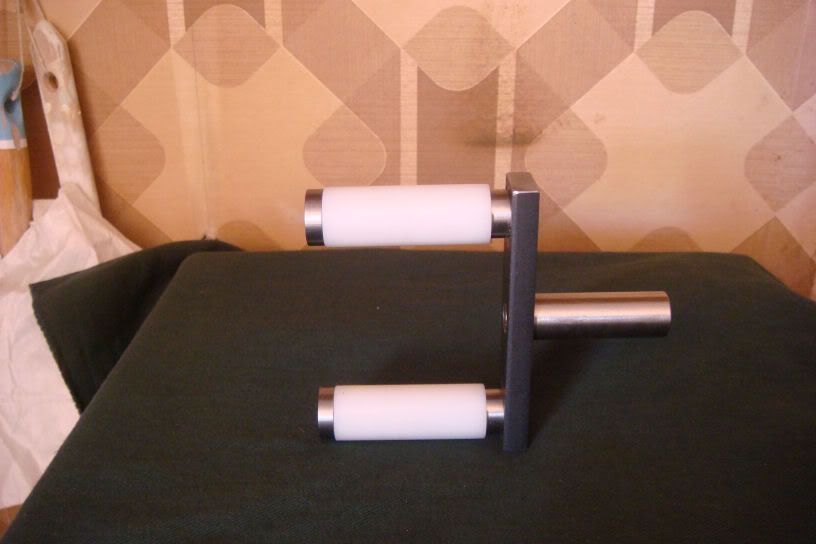
A one page drawing is in the Download Section with the name "Simple File Guide.pdf". The handle is round to facilitate mounting in the chuck or the tool post. The two parallel rollers are made in PVC; they are what guide the files and need to be substituted when excessively consumed. The other parts are in mild steel.
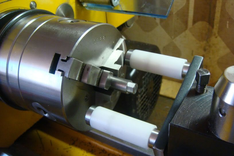
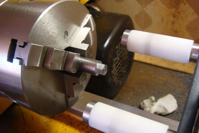
The following pictures illustrate using the tool to give a hexagon section to the end of a rod.
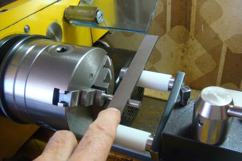
First the File Guide gets mounted in the lathe Tool Post with the plane of the rollers at a convenient angle so that movement of the cross slide adjusts the distance of the file surface from the lathe's line of centers. This adjustment is made simply by mounting a rod of the desired radius in the chuck and then moving the cross slide until the lower surface of the file is tangent to the upper surface of the rod. Lock the cross slide to maintain this position.
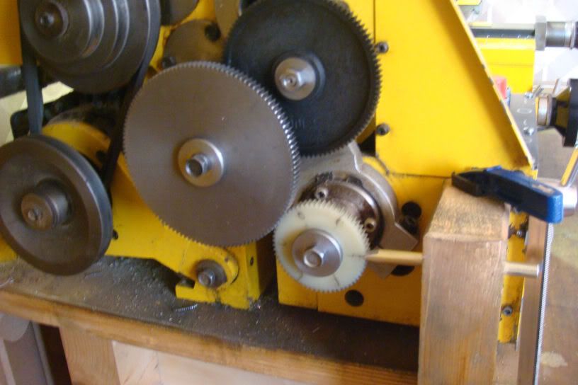
Second, the lathe gear train is set up to serve as an indexing tool for the angular position of the chuck. I set up the gear train to give a speed multiplication factor of 4. At the end of the train is a gear with 60 teeth so I end up with 240 index positions which supports all the numbers of faces I've needed and many others (2,3,4,5,6,8,10,12,15,16,20 ...). I fix the angular position of the chuck by inserting between the teeth of this wheel a fixed aluminium wedge firmly held in a block of wood. Naturally, as with the graduated wheels on the lathe slides, it is important to eliminate the systematic slack error by always turning the chuck, and hence the gear train, in the same direction.
Third mount the prepared work piece rod in the chuck. Note that to obtain distance "d" across opposite flats, it is quickest to reduce the diameter of the corresponding section of the rod to be 1.16 x d.
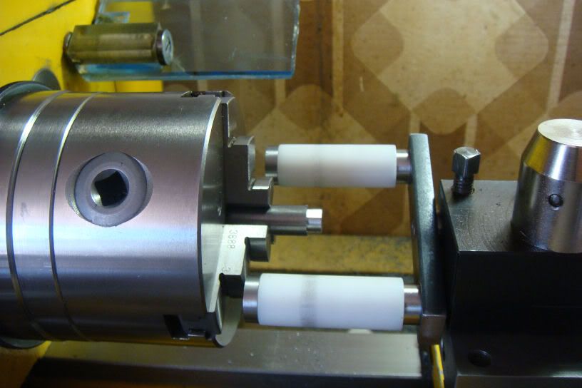
Fourth position the chuck angle for the first face, block the chuck angle and file away until the file is turning both rollers of the File Guide. Repeat for the other faces.
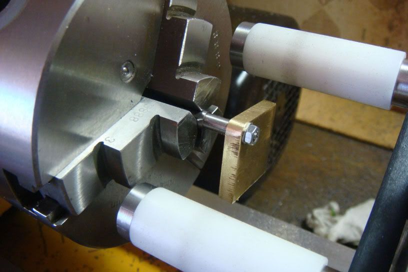
The following pictures illustrate use of the File Guide to round the corner of a bit of scrap brass plate to be concentric with a bolt hole near the corner. The plate is mounted in the chuck by means of a mandrel through the corresponding bolt hole.
First the File Guide is set up in the Tool Post as described above.
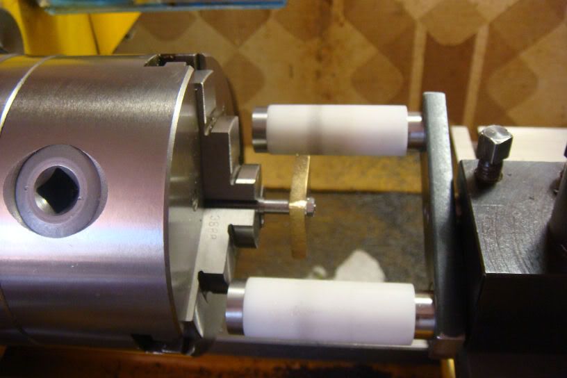
Once the File Guide is set up, the mandrel is mounted in the chuck and the manual filing operation can begin gradually turning the chuck by hand through the angle needed to generate the circular section for the corner. In the example shown the angle is 90 degrees. The final strokes of the file should be light and you should see both rollers turning indicating that you have reached the desired radius.
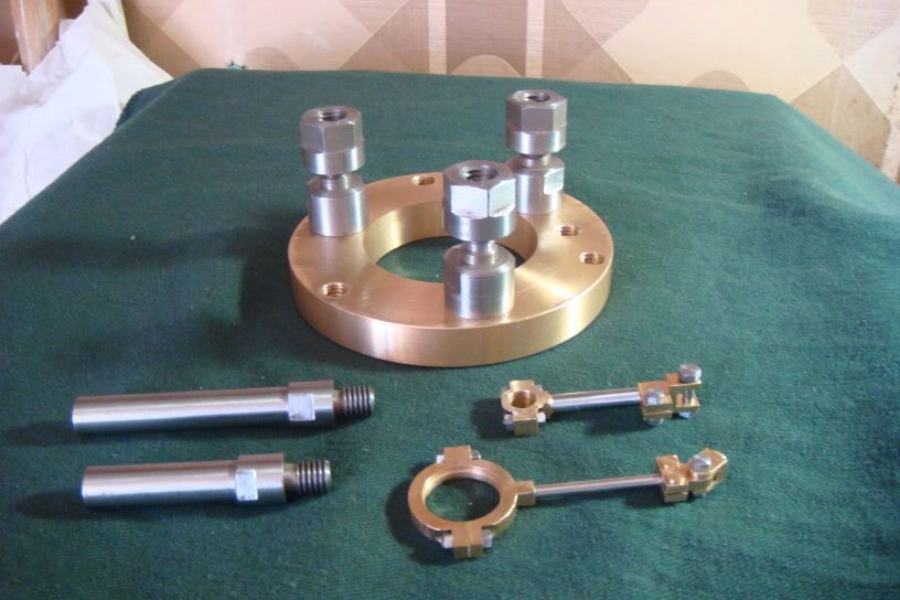
The following picture shows some other work products which have flats and/or rounds made with this tool, including the hex sections on all those 2mm nuts and bolts.
The process makes use of the lathe, without power, to position and hold the work piece while the File Guide limits the motion of the file to ensure that only the desired excess metal gets removed. Depending on the application, the File Guide may be held in the Tool Post and the work piece in the chuck or the File Guide may be held in the chuck and the work piece in a machine vice mounted on the carriage.
The picture below shows the tool.
A one page drawing is in the Download Section with the name "Simple File Guide.pdf". The handle is round to facilitate mounting in the chuck or the tool post. The two parallel rollers are made in PVC; they are what guide the files and need to be substituted when excessively consumed. The other parts are in mild steel.
The following pictures illustrate using the tool to give a hexagon section to the end of a rod.
First the File Guide gets mounted in the lathe Tool Post with the plane of the rollers at a convenient angle so that movement of the cross slide adjusts the distance of the file surface from the lathe's line of centers. This adjustment is made simply by mounting a rod of the desired radius in the chuck and then moving the cross slide until the lower surface of the file is tangent to the upper surface of the rod. Lock the cross slide to maintain this position.
Second, the lathe gear train is set up to serve as an indexing tool for the angular position of the chuck. I set up the gear train to give a speed multiplication factor of 4. At the end of the train is a gear with 60 teeth so I end up with 240 index positions which supports all the numbers of faces I've needed and many others (2,3,4,5,6,8,10,12,15,16,20 ...). I fix the angular position of the chuck by inserting between the teeth of this wheel a fixed aluminium wedge firmly held in a block of wood. Naturally, as with the graduated wheels on the lathe slides, it is important to eliminate the systematic slack error by always turning the chuck, and hence the gear train, in the same direction.
Third mount the prepared work piece rod in the chuck. Note that to obtain distance "d" across opposite flats, it is quickest to reduce the diameter of the corresponding section of the rod to be 1.16 x d.
Fourth position the chuck angle for the first face, block the chuck angle and file away until the file is turning both rollers of the File Guide. Repeat for the other faces.
The following pictures illustrate use of the File Guide to round the corner of a bit of scrap brass plate to be concentric with a bolt hole near the corner. The plate is mounted in the chuck by means of a mandrel through the corresponding bolt hole.
First the File Guide is set up in the Tool Post as described above.
Once the File Guide is set up, the mandrel is mounted in the chuck and the manual filing operation can begin gradually turning the chuck by hand through the angle needed to generate the circular section for the corner. In the example shown the angle is 90 degrees. The final strokes of the file should be light and you should see both rollers turning indicating that you have reached the desired radius.
The following picture shows some other work products which have flats and/or rounds made with this tool, including the hex sections on all those 2mm nuts and bolts.
")


![DreamPlan Home Design and Landscaping Software Free for Windows [PC Download]](https://m.media-amazon.com/images/I/51kvZH2dVLL._SL500_.jpg)